Toray NHPA Series User manual

“NHPA Series C type”
[050-1C, 100-1C,
150-1C, 2C, 3C and 4C]
Instruction
Manual
Instruction
Manual
Toray MBR
Last updated August 2022
06-G-MB2-NHPAC-220801

Instruction Manual
Toray MBR
06-G-MB2-NHPAC-220801
Notice
The data and information contained in this document are based upon rigorous technical
testing by Toray, and is to the best of our knowledge reliable. Toray cannot control design
and operating conditions, and consequently Toray does not assume any liability for results
obtained or damage incurred through the application of the information provided herein.
No liability, warranty or guarantee of nal product performance by Toray is implied by the
information provided in this document.
This manual supersedes all previous versions. Technical modication of products or
production technology may necessitate changes to information in this manual without prior
notice. Please verify that your version of the manual is the latest version available by either
contacting Toray, or checking online at www.water.toray.
Terms and Conditions of Use
When using this document, please read the Terms and Conditions of Use below thoroughly and agree to them before using
this document. By using this document, you agree to all of the Terms and Conditions of Use outlined here. The Terms and
Conditions of Use are subject to change without prior notice, so please check with Toray for the latest Terms and Conditions
of Use before using the document.
1. Intellectual Property Rights
The content in this document is protected by copyright laws in respective countries and relevant treaties. Accordingly,
the document's information may not be reproduced, altered, or distributed without permission in writing from Toray. We
permit downloading this document through Toray's website as a PDF le, stored on a personal computer, and printed
out for customers' personal use. However, we prohibit transferring this document to any other websites or printed media.
The material contained in this document may not be used without permission from the copyright holder for any other
purpose that exceeds the scope permitted under copyright law.
2. Trademarks
The "TORAY" company name used in this document is a trade name, and the names of products manufactured by
Toray are trademarks or registered trademarks. Toray's trade names and trademarks are protected under the Japanese
Trademark Law, the Unfair Competition Prevention Law, and other legislation. The trade name and trademarks may not
be used or reproduced without express permission from Toray.
3. Disclaimer
Toray takes all reasonable care in updating the information in this document. However, Toray makes no representation
and warranty of any kind, either express or implied, including without limitation, any implied warranties concerning the
accuracy, usefulness, suitability, or tness for a particular purpose of the information in the document.
Toray shall not be responsible or liable for any losses or damage incurred due to the use of the information in this
document. The information in this document is subject to change without prior notice, and Toray reserves the right to
suspend or discontinue the publication of this document.
4. Availability of Goods and Services
The goods and services contained in this document are not available in all countries and regions. Goods and services
may also be supplied under dierent trademarks in dierent countries. We ask that you contact your nearest Toray
representative oce if you wish to use the goods and services shown or implied in this document.
5. Proper Law and Court of Jurisdiction
This Terms and Conditions of Use shall be governed by and construed according to the laws of Japan. Any and all
disputes arising out of or relating to this document shall be brought to the Tokyo District Court Tokyo, Japan.

Instruction Manual
Toray MBR
06-G-MB2-NHPAC-220801
Contact Information
Toray Industries, Inc. — UF & MBR Membrane Products Department (Global Headquarters)
Nihonbashi Mitsui Tower, 1-1, Nihonbashi-Muromachi 2 chome, Chuo-ku, Tokyo, 103-8666
Japan
Tel: +81-3-3245-4542 Fax: +81-3-3245-4913
Toray Membrane USA, Inc. (TMUS)
13435 Danielson Street, Poway, California 92064 USA
Tel: +1-858-218-2360 Fax: +1-858-218-2380
Toray Membrane Europe AG (TMEU)
Grabenackerstrasse 8b, Muenchenstein 1 CH-4142, Switzerland
Tel: +41-61-415-8710 Fax: +41-61-415-8720 E-mail: info.tmeu.mb@mail.toray
Toray Asia Pte. Ltd. (TAS)
111 Somerset Road, #14-22 - #14-27, Singapore 238164, Republic of Singapore
Tel: +65-6226-0525 Fax: +65-6226-0509
Toray BlueStar Membrane Co., Ltd. (TBMC)
Zone B, Tianzhu Airport Industrial Zone, Beijing 101318, China
Tel: +86-10-8048-5216 Fax: +86-10-8048-5217
Toray Membrane Middle East LLC (TMME)
PO Box 20279, Dammam 31952, Kingdom of Saudi Arabia
Tel: +966-13-568-0091 Fax: +966-13-568-0093
Toray Advanced Materials Korea Inc. (TAK)
Korea Toray R&D Center 7, Magokdonng-ro 10-gil, Gangseo-gu, Seoul 07790, Republic of
Korea
Tel: +82-22-3279-7389 Fax: +82-2-3279-7088
website: www.water.toray

TORAY MBR
Instruction Manual 06-G-MB2-NHPAC-220801
TABLE OF CONTENTS
I. INTRODUCTION ..................................................................................................................... 1
1. Features of MBR ................................................................................................................... 1
2. Outline of “NHPA Series” ...................................................................................................... 2
II. FOR SAFE OPERATION OF “NHPA SERIES”...................................................................... 5
1. Safety Instruction for Unpacking and Installation.................................................................. 5
2. Safety Instruction for Operation and Maintenance................................................................ 6
3. Safety Instruction for Chemical Cleaning of Element ........................................................... 8
III. SPECIFICATIONS AND PERFORMANCE OF “NHPA SERIES” ........................................ 10
1. Specifications of Element.................................................................................................... 10
2. Specifications of Filtrate Tube Assembly ............................................................................ 10
3. Specifications and Performance of “NHPA Series” Module................................................ 10
IV. MEMBRANE FILTRATION PROCESS DESIGN FOR “NHPA SERIES”............................. 15
1. Standard Time Chart ........................................................................................................... 15
2. Flow Diagram of Membrane Filtration................................................................................. 16
3. Layout of “NHPA Series” Modules in Membrane Tank....................................................... 21
4. Piping................................................................................................................................... 24
V. INSTALLATION OF “NHPA SERIES”................................................................................... 28
1. Preparatory Procedure ........................................................................................................ 28
2. Unloading/Lifting Products .................................................................................................. 28
3. Checking Products .............................................................................................................. 29
4. Storing Products .................................................................................................................. 29
5. Installing Products ............................................................................................................... 30
VI. START OF OPERATION ...................................................................................................... 33
1. Clean Water Operation........................................................................................................ 33
2. Seeding Sludge Injection..................................................................................................... 34
3. Actual Filtration Operation................................................................................................... 35
VII. OPERATION CONTROL ...................................................................................................... 36
1. Standard Operating Conditions........................................................................................... 36
2. Operating Parameters ......................................................................................................... 38
3. Basic Control Philosophy .................................................................................................... 38
4. Daily Inspection ................................................................................................................... 40
VIII. MAINTENANCE OF “NHPA SERIES”.................................................................................. 43
1. Maintenance Items and Maintenance Frequency............................................................... 43
2. Air Diffuser Cleaning............................................................................................................ 44
3. Chemical Cleaning of Element............................................................................................ 46
4. Chemical Agents Available for Chemical Cleaning............................................................. 46
5. Handling of Chemical Agents.............................................................................................. 47
6. Chemical Cleaning Procedure............................................................................................. 50

TORAY MBR
Instruction Manual 06-G-MB2-NHPAC-220801
7. Lifting Procedure ................................................................................................................. 55
8. Storing Products after Use .................................................................................................. 56
9. Disposing Procedure ........................................................................................................... 57
IX. REPLACEMENT PARTS LIST ............................................................................................. 58
X. TROUBLESHOOTING.......................................................................................................... 59
XI. WARRANTY POLICY ........................................................................................................... 60
XII. REFERENCE ...................................................................................................................... 61
Symbols used in this manual
This symbol is used to indicate an imminent hazardous situation
which, if not avoided, will result in serious injury or death.
This symbol is used to indicate a potentially hazardous situation
which, if not avoided, can result in serious injury or death.
This symbol is used to indicate a potentially hazardous situation
which, if not avoided, may result in injury or property damage.
“Prohibited”
This symbol indicates a prohibited action or procedure.
“Instruction”
This symbol indicates an important action or procedure which has
to be taken without fail.
DANGER
!
WARNING
!
CAUTION
!

TORAY MBR
Instruction Manual 06-G-MB2-NHPAC-220801
1 of 61
I. INTRODUCTION
Toray MBR is the submerged membrane module suitable for the membrane bioreactor
(MBR) that has been developed based on the polymer science and the membrane
fabrication technologies accumulated for a long time in Toray Industries, Inc.
"NHPA Series" is a new model of NHP-MBR module equipped with thin membrane elements
having higher packing density, while reliable performance of Toray PVDF membrane has
been kept unchanged.
This manual explains MBR's features and describes the specifications of "NHPA Series" and
its safe operations including installation, operation, maintenance procedures and peripheral
equipment. Operators should thoroughly read this manual to ensure stable operation.
1. Features of MBR
The process flow of the conventional activated sludge system (CAS) and MBR are shown in
Fig.I-1 and Fig.I-2, respectively.
MBR provides the following advantages:
(1) Small Footprint
Unlike CAS, MBR separates sludge within an aeration tank using membranes, thus
eliminating the space for the sedimentation tank. Also with membrane, MBR can hold higher
concentration of activated sludge in the aeration tank, so its volume can be reduced. As a
result, MBR requires a smaller footprint compared to CAS.
(2) High Quality of Treated Water
MBR removes suspended solids (SS) from the sludge liquid with membrane much more
certainly than the conventional sedimentation process. MBR also rejects microorganisms
such as Escherichia coli and Cryptosporidium efficiently.
Sedimentation Tank
Wastewater
Aeration Tank
Discharge
Wastewater
Discharge or Reuse
Reuse
RO
membrane
Submerged Membrane
Module
Membrane
Tank
Fig. I-1 CAS Flow
Fig. I-2 MBR Flow
TORAY MBR
Instruction Manual 06-G-MB2-NHPAC-220801
2 of 61
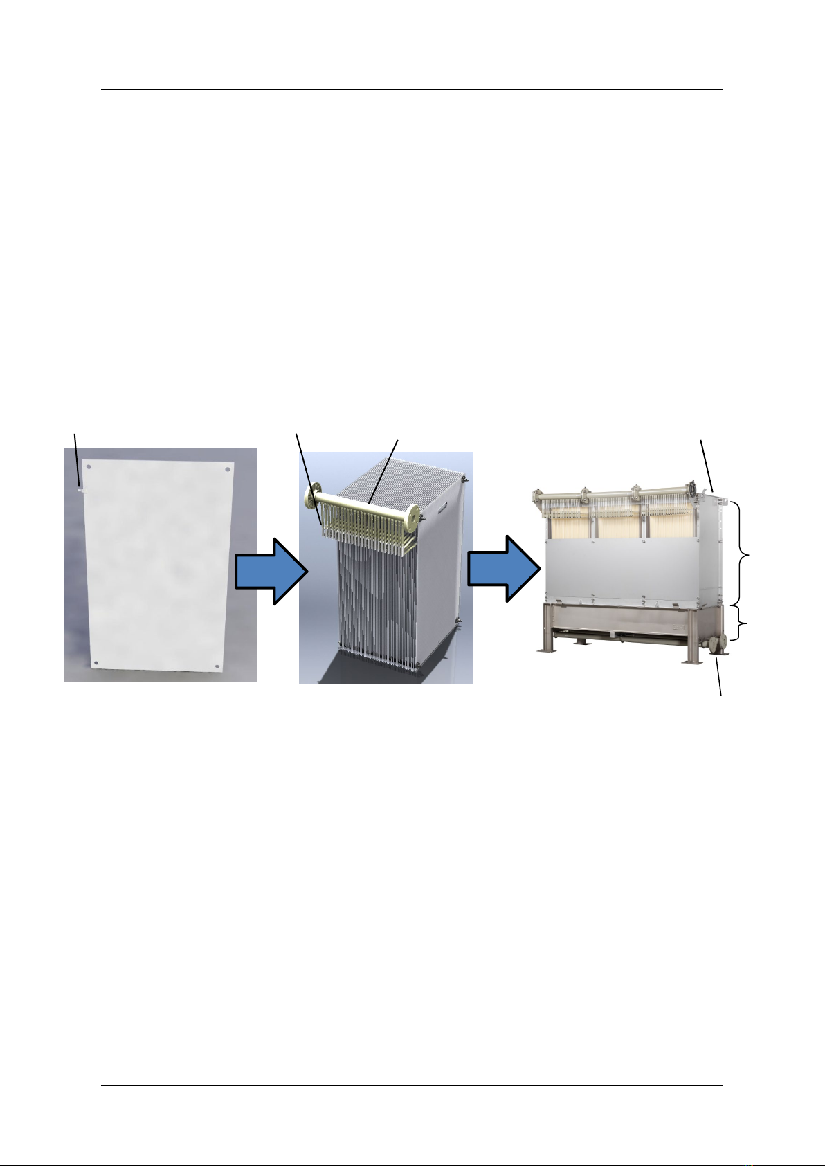
2. Outline of “NHPA Series”
“NHPA Series” is the membrane module composed of the element block and the aeration
block. The element block contains several cassettes, and in the cassette the membrane
elements, each of which consists of two flat membrane sheets, are arranged at a constant
clearance. Each element is connected via plastic tube to the filtrated water manifold. For this
-C model, the aeration block consists of coarse-bubble air diffusers to supply scouring air
(see Fig.I-3).
This module is used submerged in sludge liquid.
The following shows the features of “NHPA Series”.
Fig. I-3 Components and Appearance of “NHPA150-1C”
Nozzle
Filtrate water manifold
Tubes
Module
Frame
Cassette
Element
50 sheets
Element
block
Aeration
block
Coarse
bubble
diffuser
3 pcs
TORAY MBR
Instruction Manual 06-G-MB2-NHPAC-220801
3 of 61
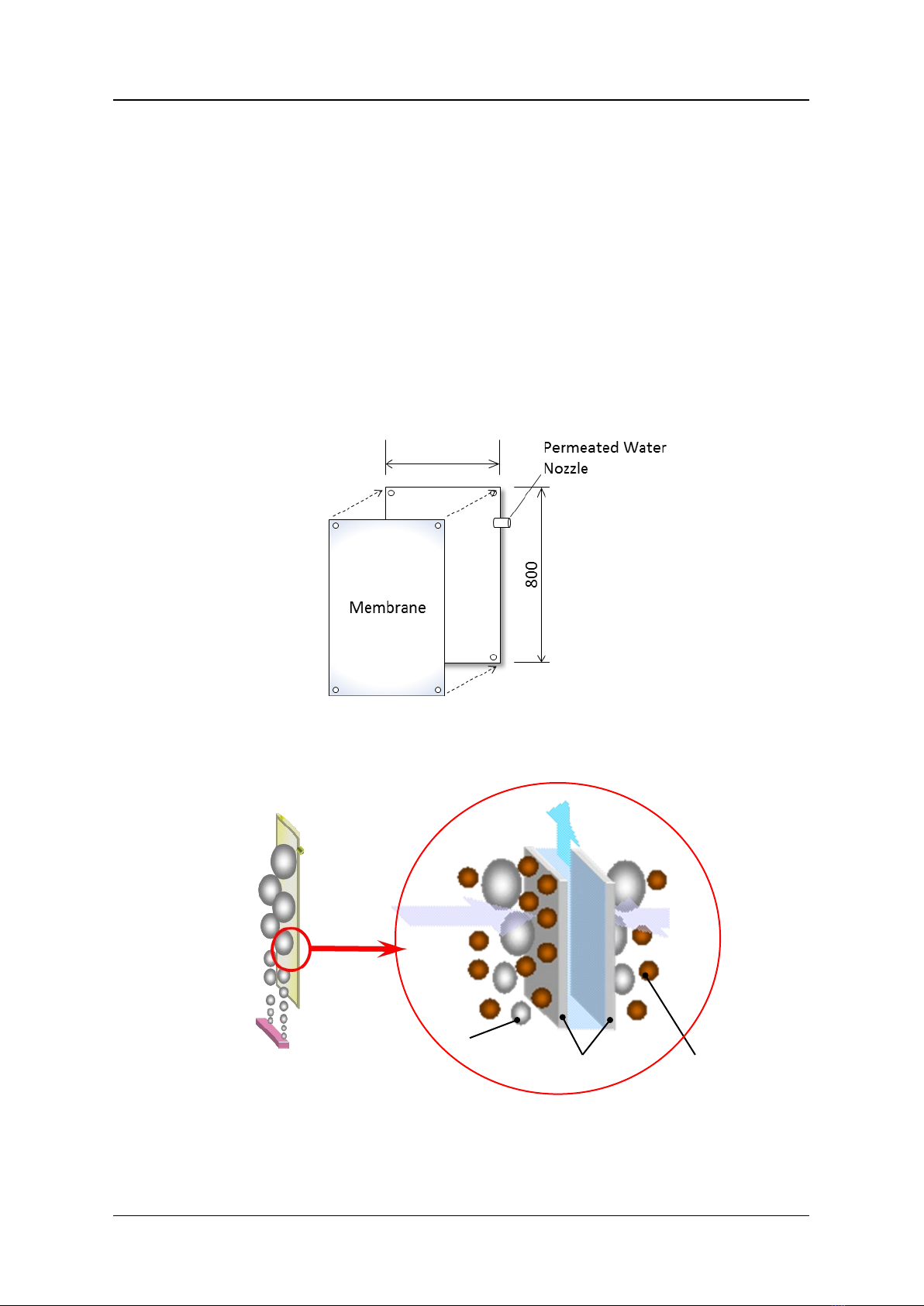
(1) Shape of Element
The membrane element is a flat sheet type as shown in Fig.I-4. At the normal filtration
operation, the sludge accumulated on the membrane surface is cleaned up effectively with
upward water stream generated with the scouring air supplied from the air diffusers installed
at the bottom side (Fig.I-5). This mechanism ensures the stable filtration since the membrane
does not easily admit of sludge adherence to its surface.
In addition, thin membrane element which consists of two membrane sheets and spacers in
between makes it possible to have higher membrane packing density in the module similar to
that of a hollow fiber membrane, and also the vibration of elements by scouring air improves
membrane cleaning efficiency.
Fig. I-4 Structure of Element
Fig. I-5 Filtration Principle of Activated Sludge
Air
Element
Filtrated water
Activated sludge
Membrane
Air
480

TORAY MBR
Instruction Manual 06-G-MB2-NHPAC-220801
4 of 61
3.0 micrometer
Fig. I-6 Membrane Surface
(photo)
Fig. I-7 Pore Size Distribution
(2) Membrane Structure
The flat sheet membrane consists of a PVDF (Polyvinylidene Fluoride) functional layer and a
base layer of PET (polyester) non-woven fabric. This structure gives the membrane superior
physical strength and high chemical resistance.
(3) Membrane Pore Size
Numerous small-size pores are distributed evenly over the membrane surface with a sharp
pore-size distribution. This structure gives an outstanding high treated water quality and
excellent water permeability, making the membrane highly resistant to clogging (see Fig.I-6
and Fig.I-7) compared to other membranes. The average pore size is 0.08 micrometer.
(4) Cassette Replacement
Membranes can be taken out and exchanged by cassette. It is possible to replace only a
cassette which contains a damaged membrane.
Pore size (micrometer)
0
0.5
1.0
1.5
0.2
0.4
0.6
0.8
0
Number of pore (10
12
/m
2
)
0.08 micrometer
TORAY MBR
Instruction Manual 06-G-MB2-NHPAC-220801
5 of 61
II. FOR SAFE OPERATION OF “NHPA SERIES”
Before using “NHPA Series”, please thoroughly read this Instruction Manual and follow the
instructions described in this manual, especially the safety precautions shown below. The
details of each precaution are described in the relevant chapter
1. Safety Instruction for Unpacking and Installation
Attach chains or slings to the lifting lugs when lifting element-deck, an
element block or aeration block of “NHPA Series”. Slowly raise the module
straight up. Avoid sudden changes in movement to minimize shaking the
module. Never allow personnel to stand under the “NHPA Series
” during
lifting.
Never lift or operate the module with worn or damaged parts. Use chains or
slings rated for the weight being lifted. Check the condition of each part
before lifting.
Do not lift upper element block and lower element block at once as one unit
when lifting NHPA150-3C or 4C
. Lift the upper and lower element block
separately.
Make provisions, in advance, to access the upper portions of the membrane
module via a scaffold or ladder when installing “NHPA Series” module. Do
not climb on the module structure. Never step on the air diffuser and filtrate
water manifold. Use protective equipment to ensure the safety of workers.
Wear the appropriate personal protective equipment (e.g. safety gloves) in
order not to cut one’s hand on the edge of the module frame.
During transportation, storage, and installation, take appropriate measures
to protect "NHPA Series" or associated components from damage. Do not
put any heavy objects directly on the module. Store the module in an area
that will minimize the risk of damage from moving equipment like forklifts etc.
Exposing the “NHPA Series” and membrane elements to temperatures
above 40 deg C or direct sunlight
should be avoided. Exposure to direct
sunlight/UV radiation will cause the polypropylene
air diffuser and filtrate
water manifold to deteriorate.

TORAY MBR
Instruction Manual 06-G-MB2-NHPAC-220801
6 of 61
Take adequate measures, during the installation process, to protect the
“NHPA Series” from: sparks emitted from welding equipment, fusion cutting,
or grinding.
Protect “NHPA Series” from freezing at all the time.
Avoid pressurizing the filtrate side of "NHPA Series”.
Install the screen with openings of 3.0 mm or under before the membrane
tank. Mesh type screen is recommended. Overflow or waste carryover must
be avoided at all the time.
Connect the flanges of air diffuser and filtrate water manifold to the piping
with the tightening torque of 20 N.m, in order to avoid distortion, leakage, or
breakage of the air diffuser and filtrate water manifold.
Consider piping materials
and regulate the load to the flange connection
points at less than 20 kg per flange in order to avoid distortion, leakage, or
breakage of the air diffuser and filtrate water manifold. If the load exceeds
the limit shown above, put some supports on the piping to reduce the load.
2. Safety Instruction for Operation and Maintenance
Filtrated water is not for potable uses. Do not drink the MBR filtrate.
Before discharging the treated water to the environment or reusing it, make
sure to analyze its quality and confirm that the water quality
meets the
intended purpose.
Do not burn the membranes without appropriate facilities since harmful
Hydrogen fluoride (HF) gas will be generated. H
ire a professional solid
waste disposal company to perform the task when
disposing of the
membrane elements.

TORAY MBR
Instruction Manual 06-G-MB2-NHPAC-220801
7 of 61
Make certain the air discharge valve is in the open position to assure any
accumulated air is released when first filling the membrane tank with clean
water or sludge. After the tank is filled with clean water,
close the air
discharge valve.
Do not use ground water for the initial filling of the membrane tank. Ground
water may contain considerable concentrations of iron, manganese, calcium,
or silica
. Naturally occurring compounds of these elements can clog the
membrane pores.
White foaming may occur in the membrane tank during clean water
operation. The foaming is caused by the leaching of residual biodegradable
hydrophilic components contained in the membrane after the manufacturing
process. Foaming is normal and does not adversely
affect the membrane
filtration process but if you want to remove this, do not use silicone-based
anti-foaming agent which may cause choking of membrane pores.
Do not operate the membranes longer than necessary to purge the system
of entrained air when using clean water in the MBR tank. Prolonged clean
water operation can clog the membrane pores.
Keep the membranes wet once they get wet. If the membranes are allowed
to dry out, the permeability of the membranes may be permanently reduced.
B
e sure to pass the seeding sludge through a screen to remove large
foreign materials when feeding the seeding sludge. It is recommended that
the screen mesh be 3 mm or smaller.
Make certain sufficient air is being
supplied to the membrane module air
diffuser before operating in the filtration mode. Failure to do so will result in
the membrane becoming clogged.
Do not allow chemicals, toxic agents, oils, or any other substances into the
MBR tank that may adversely affect the condition of the activated sludge.
If anti-
foaming agents are to be added to the membrane tank, use only
alcohol based anti-foaming products. Do not use silicone-based anti-foaming
agent which may cause choking of membrane pores.
Avoid abrupt changes to especially pH, temperature, and suction pressure,
when operating in the filtration mode, e
ven if these changes are within
acceptable operating guidelines.

TORAY MBR
Instruction Manual 06-G-MB2-NHPAC-220801
8 of 61
When it is obvious that a module part is worn and potential for failure is high,
promptly replace that part with approved replacement parts.
Never expose the “NHPA Series” to freezing temperatures at any time.
Take measures to keep the membrane elements wet
when removing the
“NHPA Series” module from the activated sludge for inspection or
maintenance
. Allowing the membrane elements to dry out will adversely
affect the membrane’s permeability.
The air scour should be stopped when the filtration process is suspended.
There are two exceptions:
1) Do not stop the air scour during the normal relaxation period.
2) Do not stop the air scour if the activated sludge requires air for normal
metabolic processes. However, under t
hese conditions the amount of air
flow directed to the diffuser should be reduced to just the amount required to
maintain sludge viability.
Once a filtrate tube has been removed or disconnected from either the
element nozzle or filtrate manifold,
it should be replaced with a Toray
approved replacement part. Old filtrate tubes lose their elasticity,
and the
integrity of the seal can be compromised.
Never use a pressure washer machine when
washing the membrane
module and element which c
an cause fatal delamination of membrane
element edge.
3. Safety Instruction for Chemical Cleaning of Element
Chemical agents used for chemical cleaning can be harmful to one’s health.
Wear protective goggles, protective gloves, and other safety gear when
handling chemicals. Make sure to check the details of its material safety
data sheet (SDS) beforehand.
If chemicals come in contact with your skin or clothes, immediately wash the
contacted area with a large volume of running water.
If chemicals splash into your eyes, immediately flush with large volumes of
running water and contact a doctor.
Immediately stop the
chemical cleaning operation if any of the associated
cleaning equipment appears to be malfunctioning.
TORAY MBR
Instruction Manual 06-G-MB2-NHPAC-220801
9 of 61
Do not inject any chemical into the membrane directly from the chemical
pump discharge. Excessive membrane element internal pre
ssure will
damage the element. Be sure to inject chemicals at a pressure less than 10
kPa (100 mbar).
Before starting injecting chemical to elements, confirm that the membrane
tank liquid level is more than 500 mm above the top of the module.
Store chemicals in a dark, cold place free from direct sunlight.
Use chemical storage tanks constructed of chemically compatible materials
to prevent corrosion.
Never mix sodium hypochlorite with heavy metals or acids.
The resulting
chemical reaction will generate toxic chlorine gas.
To avoid scattering of chemical solution turn off the air scour during a chemical
cleaning.
TORAY MBR
Instruction Manual 06-G-MB2-NHPAC-220801
10 of 61
III. SPECIFICATIONS AND PERFORMANCE OF “NHPA SERIES”
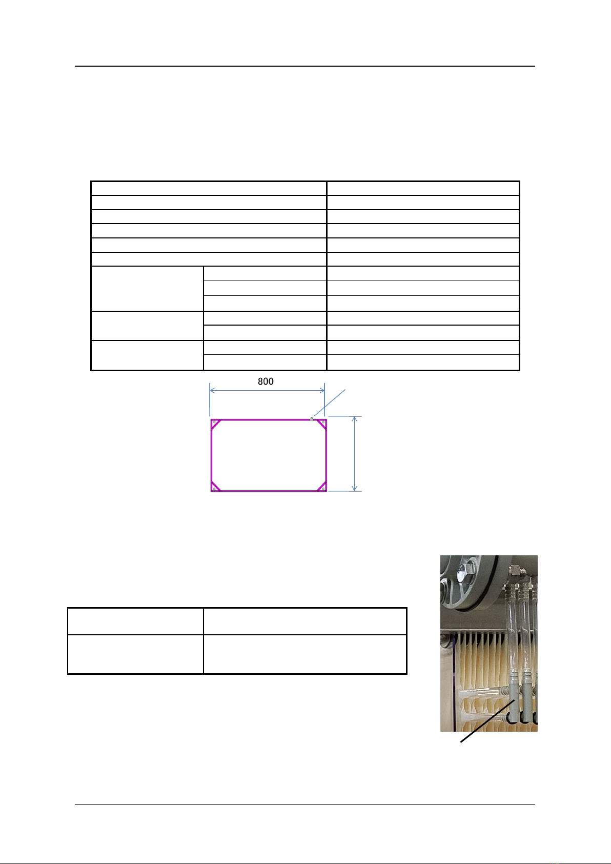
1. Specifications of Element
TableIII-1 and Fig.III-1 show the specifications and the physical dimensions for the NHPA
Series element.
Table III-1 Specifications of Element (TSP-50080)
Model name
TSP-50080
Membrane configuration
Flat sheet
Application
Filtration of activated sludge
Filtration method
Suction filtration
Nominal pore diameter (
µ
m)
0.08
Effective membrane area (m2)
0.7
Dimensions (mm)
Total width
480
Total height
800
Thickness
1.8
Weight (kg)
Dry
0.25
Wet (Reference)
0.5
Main material
Membrane
PVDF and PET non-woven fiber
Nozzle
PE
Fig.III-1 Element Appearance (mm)
2. Specifications of Filtrate Tube Assembly
Table III-2 and Fig. III-2 show the specifications and appearance of
Tube Assembly.
Table III-2 Specifications of Filtrate Tube Assembly
Material
Thermoplastic polyether-polyurethane (tube)
Polypropylene (connector)
Tube Inside diameter (mm)
Tube outside diameter (mm)
Dimensions (mm)
8
10
Approx. 125 x 155
Fig.III-2 Tube Assembly Appearance
*Two elements are connected to one manifold nozzle via tubes and connector
Nozzle
480
Connector

TORAY MBR
Instruction Manual 06-G-MB2-NHPAC-220801
11 of 61
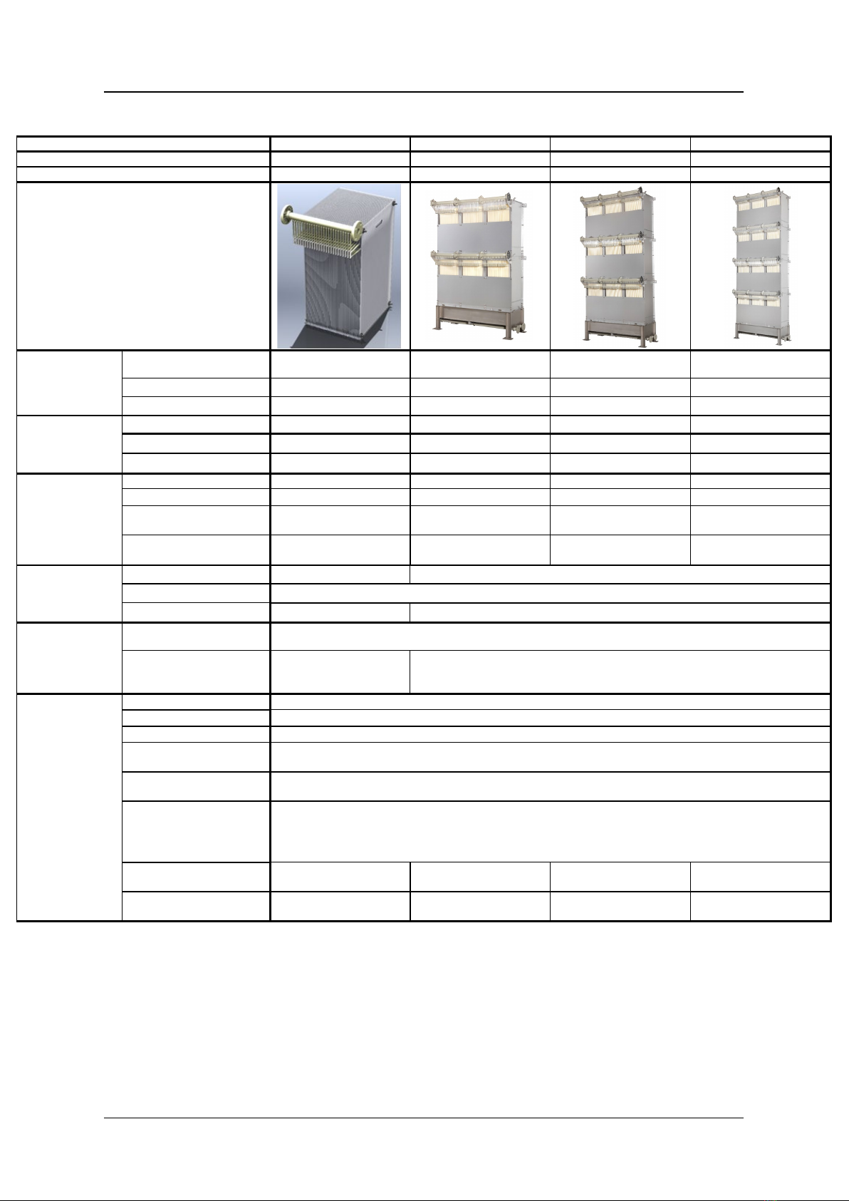
3. Specifications and Performance of “NHPA Series” Module
Figure III-3 shows the cassette arrangement of “NHPA Series” modules shown in this
Instruction Manual. Table III-3a shows the specifications of NHPA050-1C, 100-1C and
150-1C cassette and modules. Table III-3b shows the specifications of NHPA-150-2C, -3C,
and -4C cassette and modules.
Note that NHP210-300S and -600D are described in the separate Instruction Manual.
Contact Toray in case of replacing existing Toray MBR “TMR Series” or “NHP210 Series”
with “NHPA Series”.
Fig. III-3 Cassette Arrangement of the NHPA Modules Shown in This Manual
EBL050
EBL100
Cassette “ECS035”
ABL050-C
ABL100-C
ABL150-C
EBL150
EBL150
EBL150
+
+
+
⇩
⇩
⇩
Bolts/nuts
EBL150
+
+
EBL150
EBL150
Bolts/nuts
+
+
EBL150
EBL150
Bolts/nuts
+
+
EBL150
EBL150
Bolts/nuts
+
+
ABL150-C
ABL150-C
ABL150-C
+
+
+
NHPA050-1C
NHPA100-1C
NHPA150-1C
NHPA150-4C
NHPA150-3C
NHPA150-2C
⇩
⇩
⇩

TORAY MBR
Instruction Manual 06-G-MB2-NHPAC-220801
12 of 61
Table III-3a Specifications of Cassette and Module (NHPA050-1C, 100-1C and 150-1C)
Model name
ECS035 (Cassette)
NHPA050-1C
NHPA100-1C
NHPA150-1C
Number of membrane elements
50
50
100
150
Cassette structure
-
1 cassette x 1 deck
2 cassettes x 1 deck
3 cassettes x 1 deck
Appearance
Overall
dimensions (mm)
Width
485
(excluding nozzle&hose)
738 738 763
Length
440
660
1,130
1,617
Height
820
1,404
1,404
1,404
Dimensions
excluding filtrate header
pipes and air diffuser
pipe
(mm)
Width
-
565
565
565
Length
-
501
986
1,460
Height
-
1,320
1,320
1,320
Weight
(kg)
Module (dry)
N/A
70
110
170
Aeration block (dry)
N/A
20
30
55
Cassette/Element block
(dry)
17 50 80 115
Cassette/Element block
(sludge clogging)
*1
145 175 340 500
Material
Frame
-
304SS (316LSS is available as option)
Filtrate water manifold
Polypropylene
Air diffuser
-
304SS (316LSS is available as option)
Polypropylene
Connection
Manifold
ANSI 1 1/2 inch flange using M12 bolts/nuts
One flange per module
Air diffuser -
ANSI 1 1/4 inch flange
Using M12 bolts/nuts
Two flanges per Aeration block
ANSI 1 1/2 inch flange
Using M12 bolts/nuts
Two flanges per Aeration
block.
Operating range*3
Temperature
5-40 deg C
pH*2 of liquid
5-10
MLSS
Not higher than 18,000 mg/L
Trans-membrane
pressure
Not higher than 20 kPa (200 mbar)
Cleaning chemicals feed
pressure
Not higher than 10 kPa (100 mbar)
Cleaning chemicals and
chemicals concentration
Sodium hypochlorite (effective chlorine concentration)
:2,000-6,000 mg/L(10<pH<12)
Oxalic acid :0.5-1.0wt%
Citric acid
:
1.0-3.0wt%
Scouring Air Flow rate
(NL/min/Module)
*4
-*5 330 - 670 670 - 1,340 1,000 - 2,000
Scouring Air Flow rate
(Cubic feet/min/Module)
*4
-*5 12 - 24 24 – 48 35 – 71
*1 The weight assumed in the case of sludge clogging between elements.
*2 Except when the chemical cleaning with the designated chemical agents.
*3 For the standard operating condition refer to the Instruction Manual.
*4 Air volume as being 0 deg C and 101.325 kPa (1 atm).
*5 MBR operation only by Cassette is not assumed.
TORAY MBR
Instruction Manual 06-G-MB2-NHPAC-220801
13 of 61
Table III-3b Specifications of Cassette and Module (NHPA150-2C, 3C and 4C)
Model name
ECS035 (Cassette)
NHPA150-2C
NHPA150-3C
NHPA150-4C
Number of membrane elements
50
300
450
600
Cassette structure
-
3 cassettes x 2 decks
3 cassettes x 3 decks
3 cassettes x 4 decks
Appearance
Overall
dimensions (mm)
Width
485
(excluding nozzle&hose)
763 763 763
Length
440
1,617
1,617
1,617
Height
820
2,304 *6
3,204
4,104*6
Dimensions
excluding filtrate header
pipes and air diffuser
pipe
(mm)
Width
-
565
565
565
Length
-
1,460
1,460
1,460
Height
-
2,220
3,120
4,020
Weight
(kg)
Module (dry)
N/A
285
400
515
Aeration block (dry)
N/A
55
55
55
Cassette/Element block
(dry)
17 230 345 460
Cassette/Element block
(sludge clogging)
*1
145 1,000 1,500 2,000
Material
Frame
-
304SS (316LSS is available as option)
Filtrate water manifold
Polypropylene
Air diffuser
-
Polypropylene
Connection
Manifold
ANSI 1 1/2 inch flange using M12 bolts/nuts
One flange per each deck (2C: 2 pcs per module, 3C: 3 pcs per module, 4C: 4 pcs per module)
Air diffuser -
ANSI 1 1/2 inch flange
Using M12 bolts/nuts
Two flanges per Aeration block.
Operating range*3
Temperature
5-40 deg C
pH*2 of liquid
5-10
MLSS
Not higher than 18,000 mg/L
Trans-membrane
pressure
Not higher than 20 kPa (200 mbar)
Cleaning chemicals feed
pressure
Not higher than 10 kPa (100 mbar)
Cleaning chemicals and
chemicals concentration
Sodium hypochlorite (effective chlorine concentration)
:2,000-6,000 mg/L(10<pH<12)
Oxalic acid :0.5-1.0wt%
Citric acid
:
1.0-3.0wt%
Scouring Air Flow rate
(NL/min/Module)
*4
-*5 1,000 - 2,000 1,300 - 2,000 1,300 - 2,000
Scouring Air Flow rate
(Cubic feet/min/Module)
*4
-*5 35 - 71 46 - 71 46 - 71
*1 The weight assumed in the case of sludge clogging between elements.
*2 Except when the chemical cleaning with the designated chemical agents.
*3 For the standard operating condition refer to the Instruction Manual.
*4 Air volume as being 0 deg C and 101.325 kPa (1 atm).
*5 MBR operation only by Cassette is not assumed.
*6 Check tank height and piping condition when using this module for replacement of existing Toray MBR
TMR140-100S or NHP210-300S/600D since NHPA is a little taller than existing modules.

TORAY MBR
Instruction Manual 06-G-MB2-NHPAC-220801
14 of 61
Table III-4 and III-5 shows the performance of ”NHPA Series” modules.
Table III-4 Filtrate water quality (Reference value)
Model name All models
Filtrate
water
quality*1
TSS (mg/L) *2 Not higher than 3.0
Turbidity (NTU) *3 Not higher than 1.0
*1 This value can be attained when operated under the standard operating conditions as specified in this
Instruction Manual and Operation and Maintenance guideline during a period specified separately by
Toray.
*2 Measuring method of TSS is complied with Standard Method of Examination of Water and Wastewater
20th Edition (1998), Section 2540D, Total Suspended Solids Dried at 103-105 deg C or ISO 11923.
*3 Measuring method of NTU is complied with Standard Method of Examination of Water and Wastewater
20th Edition (1998), Section 2130, Turbidity or ISO 7027.
Table III-5 Flow capacity (Reference value)
Model name NHPA050-1C NHPA100-1C NHPA150-1C
Filtration
Flow (m3/d)
*4
Sewage 3-25 7-50 10-75
Industrial wastewater 3-17 7-33 10-50
Model name NHPA150-2C NHPA150-3C NHPA150-4C
Filtration
Flow (m3/d)
*4
Sewage 20 - 150 30-225 40 - 300
Industrial wastewater 20 - 100 30-150 40 - 200
*4 This value is just a reference value and not a guaranteed value of Toray. Sustainable operating filtration
flow capacity varies among the plant depending on the type of wastewater, total process design, and
operating condition. In case of industrial wastewater application, it is strongly recommended to conduct
a pilot test before membrane tank designing.

TORAY MBR
Instruction Manual 06-G-MB2-NHPAC-220801
15 of 61
IV. MEMBRANE FILTRATION PROCESS DESIGN FOR “NHPA SERIES”
This section will address the following for the Toray “NHPA Series”: Standard sequence of
operation/time chart, illustrated piping, flow schema, and module(s) layout in the membrane
tank.
1. Standard Time Chart
Usually intermittent filtration (filtration with relaxation) is recommended. The most common
mode of filtration operation is nine (9) minutes of filtration followed by one (1) minute
of suspended membrane filtration (membrane relaxation) with continued air scour, as
shown in Fig.IV-1. This period of relaxation, with no filtration, allows the continued air scour
to be more effective at removing solids that may have accumulated on the surface of the
membrane. Intermittent filtration followed by a relaxation period is recommended for stable
and efficient membrane filtration.
The air scour should be suspended when the filtration process is stopped except for the
following conditions:
1) During normal membrane relaxation periods.
2) During suspended filtration operation unless aeration is required for mixing or biological
demand requirements. For the latter the air flow should be reduced to minimum flow
rates to prevent membrane damage.
* During low wastewater supply period, basically all modules should be in operation at lower
flux rate, considering maintaining viable activated sludge. In case operation of some or all
modules will be shut down, the air scour for those modules should be suspended or applied
intermittently following the above description. For long-term shutdown, refer to the following
Section 9, chapter VIII “Storage Products after Use”.
Fig.IV-1 Recommended Time Chart for Intermittent Filtration
Filtration
Air diffusion
Continuous Operation
Filtration: 9 min.
Relaxation: 1 min.
Cycle of 10 minutes
F1: Average flow rate for treatment capacity
and membrane area calculation
F2: Filtration flow rate for suction pump
capacity calculation
F1
F2
Other manuals for NHPA Series
1
This manual suits for next models
6
Table of contents
Other Toray Industrial Equipment manuals


