Lintec HX-0020J Series User manual
LN0538E2108D0
Heat Exchanger
Instruction Manual
HX-0020J Series
Safety precautions
Incorrect handling may cause death or injury.
(1) Before connecting with the fittings, check if no damageorproblemsare found on
the fittings. Connectproperly and makesure that leak test is conducted before
actual operation to prevent fluid from leaking into theatmosphere (Hereinafter,
the fluid used is referred as "gas" or "fluid").
(2) DO NOT apply any fluids corrosive to materials exposed to gas. Corrosion
may cause fluid to leak into the atmosphere. Please confirm the physical
properties of fluid before using.
(3) Thisdeviceisnotdesignedasanexplosion-proofstructure.
DONOTuse thisdevice in aplace where explosion-proofstructure are required.
Doing so may cause fireor explosion.
(4) Prepare temperature controller unit when operating Vaporizer/Heat
Exchanger and do not set the temperature over than maximum operating
temperature. Wring temperature setting may cause fire or destruction of the
device. It is recommended to add abnormal overheating detector if
necessary.
(5) This device must be earthed before use. Otherwise, there is the risk of
electric shock.
(6) Thermal switch is equipped in Vaporizer/Heat Exchanger to prevent
overheating. However, the operating temperature of thermal switch would
vary due to operating conditions and ambient temperature.
(7) Attach/remove connector and terminals, please make sure that power supply
turning off. It may cause fire or shock hazard.
Incorrecthandlingcancausemediumor slightinjuryor
maycause damageto,orlossof,facilities orequipment.
(1) Observe the listed in the WARNING (above).
(2) Use out-of-spec power supply will cause electric shock, fire, and
malfunction of device.
(3) This device is not designed to be waterproof. DO NOT locate this device
outdoors or in a place where it may be splashed with water. Doing so may
cause fire, trouble, or malfunction of the device.
(4) DO NOT modify this device. Modification may result in fire or failure of
the device.
(5) A warm-up period of 60 minutes is recommended after reaching the set
temperature. Otherwise, the output gas temperature will be low.
(6) This device is a precious device, please handle it carefully. Dropping down
or handing it carelessly will cause damage. Please use assist instrument
while moving or setting the device.
(7) Please use a screw with depth of 5mm or less from the case surface when
mounting HX by the hole on the surface (M3). It will crush the internal
surface of the product, and lead the break.
(8) The surface of device gets high temperature while heating up. Please wrap
up the device to prevent careless touch. Please be careful to deal with the
device while it is working because of the risk of burning from high
temperature. Please conduct replacement after checking that the device has
cooled down.
1. Introduction
This manual explains basic operation of the HX-0020J Series (Hereinafter
referred as "HX"). Please read through this manual carefully to familiarize
yourself with the features of HX.
.
2. Summary
HX is an ultra-clean high efficiency fluid heat exchanger unit employing Lintec’s
high efficiency liquid vaporization technology with maximum operating
temperature up to 200 °C and maximum heat exchange rate up to 10SLM. This
apparatus is employed over a wide range of applications from semiconductor
industries to other major manufacturing sectors.
3. Features
RoHS compliant.
4. Specification/ Dimensions
(1) Specification
Product name
Heat Exchanger
Model
HX-0020J Series
Flow rate (N2)
10SLM
Pressure loss(N2)
24kPa (10SLM, 200°C)
Withstand pressure
(Gauge pressure)
1 MPa(G)
Leak integrity
Less than 1×10-11Pa·m3/sec (He)
Operating condition
Continuous operation
Operating temperature
15 to 50ºC (Without dew condensation)
Maximum operating
temperature
200ºC
Recommended temperature
control method
PID control
Material exposed to gas
Stainless steel 316L / Stainless steel 316L(EP)
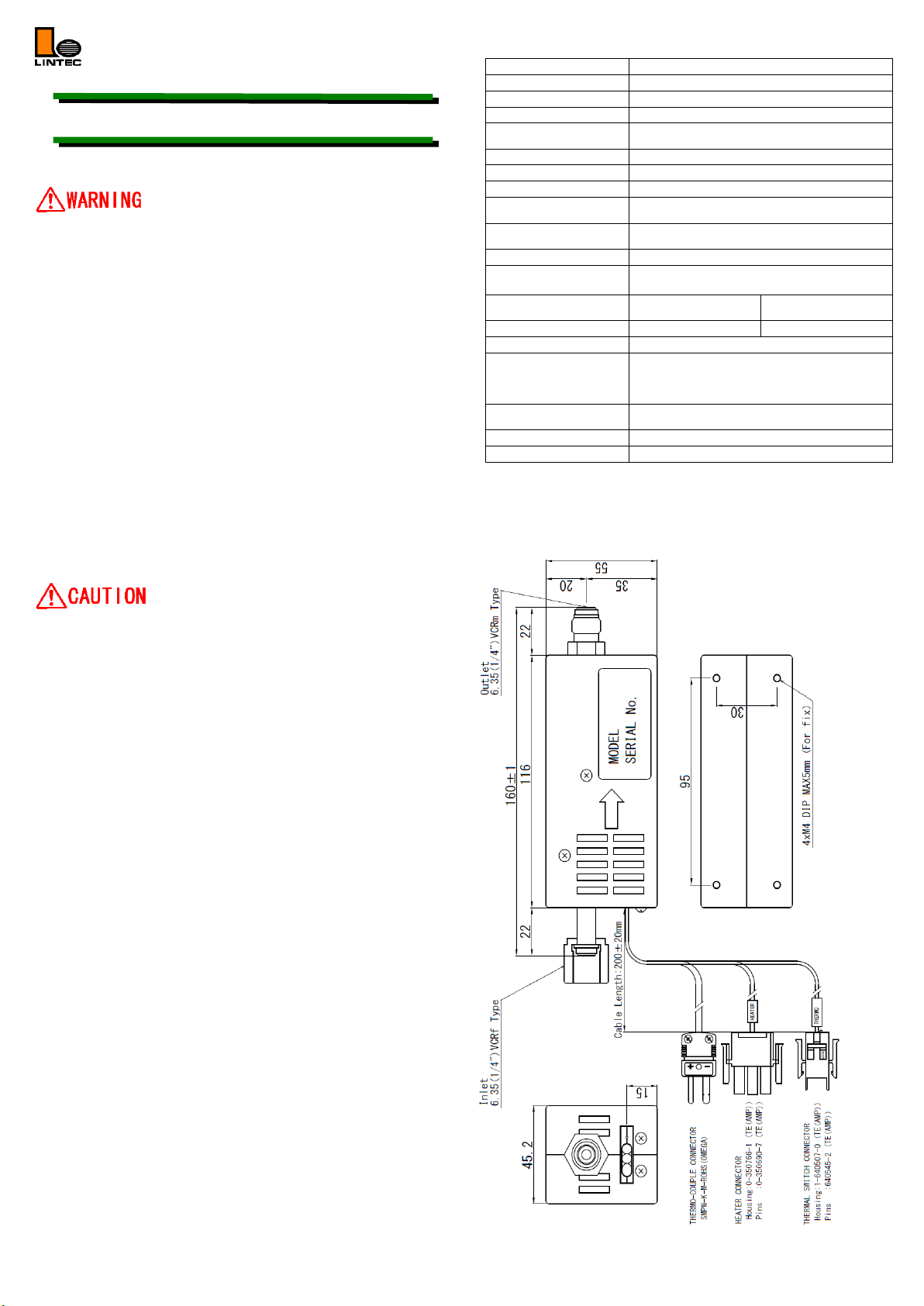
Fitting
Inlet: 6.35mm (1/4”)VCR type female
Outlet: 6.35mm (1/4”)VCR type male
Heater
120V 100W
(100V 69.4W)
240V 100W
(200V 69.4W)
Power source
AC100 to 120V
AC200 to 240V
Thermocouple
K type 1pc
ThermalswitchSpecification
(Note1)
Over 230±10ºC OPEN
Return operating temperature 200±15ºC CLOSE
Electrical rating (With resistance load)
DC42V/200mA, Min:10mA
Mounting position
Free,
Except Upright with the connectors on the top
Weight
Approx.1kg
Standard accessories
None
Note1) In actual operation, there may be a difference between the temperature at the
temperature control point and the temperature at which the thermal switch operates.
(2) Dimensions

5. Ordering information
HX-0020J-44 TK3 N L03 T23 NNN
[1] [2] [3] [4] [5] [6] [7]
[1] Series Model:
HX: Heat Exchanger Series
[2] Fitting size
44: IN 6.35mm (1/4in), OUT 6.35mm (1/4in)
[3] Fitting type
TK3: VCR type [IN female, OUT male]
[4] Internal treatment
N: No polishing (※Standard Specification)
E: Electrical polishing (※Option)
[5] Heater type
L03: AC120V 100W
L04: AC240V 100W
[6] Thermal switch
T23: 230 ±10 ºC
[7] Option
NNN: Standard specification
※Notation other than NNN means customer options. The specification will be
different from this specification sheet, please refer to specific specification sheet
please notice that the pin assignment may be different as well.
6. Connection
(1) Heater Connectors
Housing : 0-350766-1 (TE(AMP))
Pin : 0-350690-7 (TE(AMP))
Pin No.
Signal name
1
L03:120V 100W
L04:240V 100W
2
3
Case Gnd.
(2) Thermal switch Connectors
Housing : 1-640507-0 (TE(AMP))
Pin : 640545-2 (TE(AMP))
Pin No.
Signal name
1
Thermal switch
2
(3) Thermocouple Connectors
Equipped Connector : SMPW-K-M-ROHS (OMEGA)
Applicable Connector : SMPW-K-F-ROHS (OMEGA)
Pin No.
Signal name
K
K Type Thermocouple (-)
+
K Type Thermocouple (+)
7. Preparation and Operational Procedure
(1) Please prepare temperature control unit.120V100W(240V100W) heaters is
used. Please take care with respect to the heater capacities. In addition,
temperature control unit with built-in safety mechanisms is recommended
for temperature control point. As the built-in thermocouple is K type, please
select unit which is compatible with this type of thermocouple.
(2) Please be sure to use safety devices such as circuit breakers to prevent surge
currents and short circuits.
(3) Please be careful to attach this device in the direction of the gas flow. In
order to prevent a decrease in the gas temperature after heat exchange has
taken place, please heat the piping between the gas outlet and the next piece
of machinery.
(4) Please carry out connections according to the connector table. This device
has a built-in 230ºC thermal switch.
(5) The heater can be affected by humidity during storage. Ensure that
insulation resistance is above 20M ohm. If the insulation resistance drops
below 20M ohm, dry the HX and ensure that insulation resistance is above
20M ohm.
(6) Supply power, set the temperature to the desired value using the
temperature control units and allow 60 minutes for the device to stabilize
after the set temperature has been reached. Even though the temperature
control unit display temperature may be stable the temperature of the body
of the device is not. In order to achieve good heat exchange efficiency
please allow this device to stabilize before use.
(7) Estimated gas temperatures can be found from the graphs in the upper right.
However, this data is for nitrogen gas and should not be applied as is to
gases other than nitrogen. Please use this data only as a guide.
8. Product reference data
Since this data is for nitrogen, it cannot be applied directly to gases other than
nitrogen. Please use as a guide.
(1) Heat exchanger outlet gas temperature
< Measurement conditions >
·Heat exchanger set temperature: 50, 100, 150, 200°C
·Gas used: N2
·Measuring room temperature: 25°C
·Secondary line temperature control: None
(No heat insulating material, open to atmosphere)
·Secondary pressure: atmospheric pressure
(2) Pressure loss data
< Measurement conditions >
·Heat exchanger set temperature: 100, 150, 200°C
·Gas used: N2
·Measuring room temperature: 25°C
·Secondary pressure: atmospheric pressure
9. Product Warranty
(1) Period
This product is guaranteed for 1 year from the date of shipment.
Defects are repaired according to the following regulations.
(2) Scope
Warranty coverage is restricted to this product only. Any other damage caused
by this product is not covered.
(3) Disclaimer facts
The following repairs are not covered by the warranty:
1) Failure caused by product of gas or liquid used.
2) Failurecausedbymisuse(includingcarelessoperation),incorrectrepairormodification.
3) Failure cause by falling or dropping after purchase.
4) Failure caused by fire,earthquake, flood,lightning,orother naturaldisasters.
Even if the warranty period is still in effect, repair service may not be provided
in the following cases.
1) When the kind of fluid used in the product is unclear.
2) Theproductisreturnedwithfluid remaininginside, and safetycannotbeconfirmed.
This instruction manual is subject to revision without notice.
http://www.lintec-mfc.co.jp
CorporateHeadquarters
4-1-23Sekinotsu,OtsuCity,ShigaPref.520-2277,Japan
TEL. +81-(0)77-536-2210FAX.+81-(0)77-536-2215
TokyoBranchOffice
3FHattoriBuild.,4-30-14YotsuyaShinjyuku-kuTokyo160-0004,Japan
TEL. +81-(0)3-5366-2801FAX.+81-(0)3-3341-3513
Other Lintec Industrial Equipment manuals


