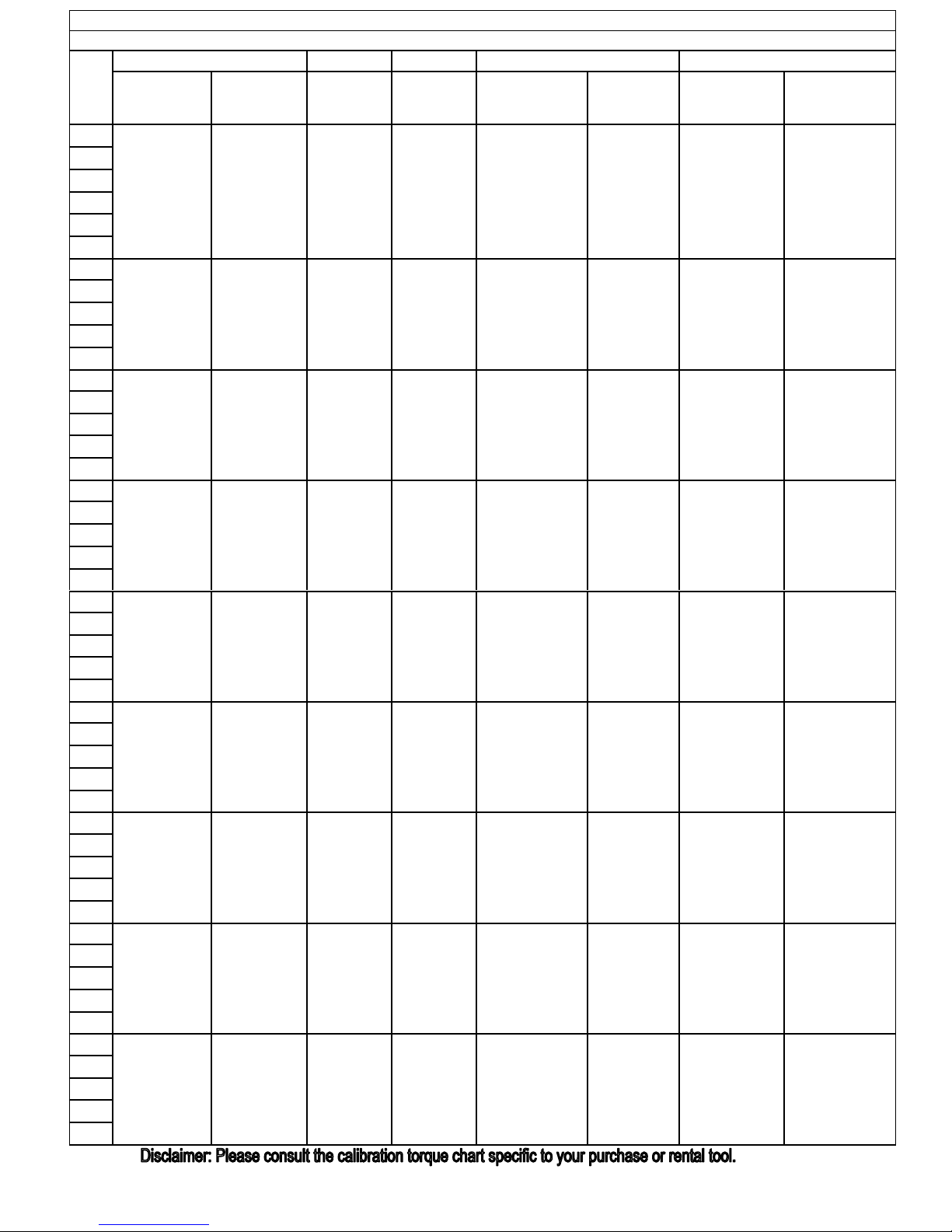
TX Series Torque Conversion Chart
P.S.I./FT./lbs
TX-2 TX-4 TX-8 TX-16 TX-32
Hex 3/4" to 1-13/16"1-7/8" to 2-3/8"All Hex SizesAll Hex Sizes2-5/8" to 3-15/16" 4" to 4-5/8" 2-7/16" to 4-5/8"4-11/16" to 6-1/2"
Sizes 19 to 46MM 47 to 60MM All Hex SizesAll Hex Sizes 65 to 100MM 105 to 115MM 80 to 115MM 115 to 155MM
P.S.I. ft./lbs. ft./lbs. ft./lbs. ft./lbs. ft./lbs. ft./lbs. ft./lbs. ft./lbs.
1,000 192 210 395 830 1,560 1,660 3,190 3,700
1,200 230 252 475 1,001 1,870 1,992 3,880 4,440
1,400 269 294 555 1,173 2,180 2,324 4,570 5,180
1,600 307 336 630 1,344 2,495 2,656 5,260 5,920
1,800 346 378 710 1,516 2,805 2,988 5,950 6,660
2,000 385 420 790 1,688 3,120 3,320 6,636 7,400
2,200 422 462 870 1,865 3,430 3,652 7,282 8,140
2,400 461 504 950 2,042 3,740 3,984 7,928 8,880
2,600 500 546 1,025 2,219 4,050 4,316 8,574 9,620
2,800 537 588 1,105 2,396 4,365 4,648 9,220 10,360
3,000 578 640 1,185 2,574 4,675 4,980 9,866 11,100
3,200 614 681 1,265 2,775 4,990 3,560 10,512 11,840
3,400 653 724 1,345 2,976 5,300 5,644 11,158 12,580
3,600 691 766 1,420 3,177 5,610 5,976 11,804 13,320
3,800 730 809 1,500 3,378 5,925 6,308 12,450 14,060
4,000 771 855 1,580 3,580 6,235 6,650 13,201 14,800
4,200 806 894 1,660 3,735 6,550 6,983 13,861 15,540
4,400 845 937 1,740 3,891 6,860 7,315 14,521 16,280
4,600 883 980 1,815 4,046 7,170 7,648 15,181 17,020
4,800 922 1,022 1,895 4,202 7,485 7,980 15,841 17,760
5,000 964 1,070 1,975 4,358 7,795 8,360 16,500 18,500
5,200 998 1,112 2,055 4,538 8,105 8,694 17,163 19,240
5,400 1,037 1,155 2,135 4,718 8,420 9,029 17,826 19,980
5,600 1,075 1,198 2,210 4,898 8,730 9,363 18,489 20,720
5,800 1,114 1,241 2,290 5,078 9,045 9,698 19,152 21,460
6,000 1,156 1,285 2,370 5,258 9,355 10,100 19,815 22,200
6,200 1,190 1,327 2,450 5,410 9,665 10,437 20,448 22,940
6,400 1,229 1,370 2,530 5,562 9,975 10,773 21,081 23,680
6,600 1,267 1,412 2,605 5,715 10,290 11,110 21,714 24,420
6,800 1,305 1,455 2,685 5,867 10,600 11,447 22,470 25,160
7,000 1,349 1,500 2,765 6,020 10,915 11,720 22,981 25,900
7,200 1,382 1,541 2,845 6,186 11,225 12,055 23,638 26,640
7,400 1,421 1,583 2,925 6,352 11,535 12,390 24,295 27,380
7,600 1,460 1,626 3,000 6,519 11,850 12,725 24,952 28,120
7,800 1,497 1,669 3,080 6,685 12,160 13,005 25,609 28,860
8,000 1,542 1,715 3,160 6,852 12,475 13,510 26,265 29,600
8,200 1,574 1,755 3,240 7,023 12,785 13,848 26,922 30,340
8,400 1,613 1,798 3,320 7,195 13,095 14,186 27,579 31,080
8,600 1,651 1,840 3,395 7,366 13,405 14,523 28,236 31,820
8,800 1,690 1,883 3,475 7,538 13,720 14,861 28,893 32,560
9,000 1,735 1,929 3,555 7,710 14,030 15,020 29,550 33,300
9,200 1,766 1,969 3,635 7,894 14,345 15,354 30,206 34,040
9,400 1,805 2,011 3,710 8,078 14,655 15,688 30,862 34,780
9,600 1,843 2,054 3,790 8,262 14,965 16,021 31,518 35,520
9,800 1,882 2,097 3,870 8,446 15,280 16,355 32,174 36,260
10,000 1,928 2,145 3,950 8,630 15,595 16,600 32,830 37,000