Torin BIG RED T32001 User manual
OWNER’S MANUAL
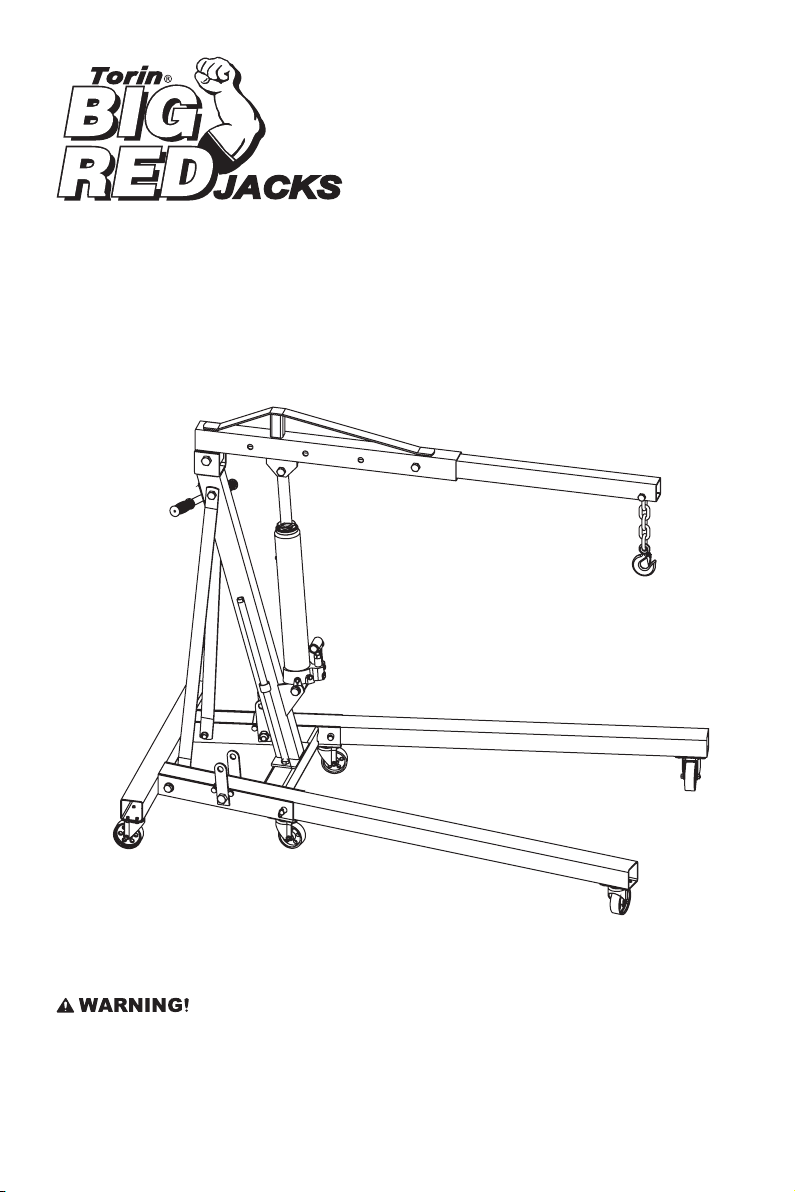
2-TON HYDRAULIC ENGINE CRANE
Item: T32001
Questions, problems, missing parts? Before returning to your retailer, call our customer service department at
1-888-44-TORIN (1-888-448-6746), 8 a.m.- 5 p.m., PST, Monday-Friday.
Read carefully and understand all ASSEMBLY AND OPERATION INSTRUCTIONS before operating. Failure
to follow the safety rules and other basic safety precautions may result in serious personal injury.
Version 20170306

2
IMPORTANT
OWNER / USER RESPONSIBILITY
INTENDED USE
Before You Begin Register This Product.
For future reference, record the model name, model number, date of manufacture and purchase date of this
product. You can nd this information on the product.
Model Name ________________________
Model Number ________________________
Date of Manufacture _______________________
Date of Purchase ________________________
DO NOT OPERATE OR REPAIR THIS PRODUCT WITHOUT READING THIS MANUAL.
Read and follow the safety instructions. Keep Instructions readily available for operators. Make certain all
operators are properly trained and understand how to safely and correctly operate the product. By proceeding
you agree that you fully understand and comprehend the full contents of this manual. Failure to operate this
product as intended may cause injury or death. The manufacturer is not responsible for any damages or injury
caused by improper use or neglect. Allow product operation only with all parts in place and operating safely.
Use only genuine replacement parts. Service and maintain the product only with authorized or approved
replacement parts; negligence will make the product unsafe for use and will void the warranty. Carefully
inspect the product on a regular basis and perform all maintenance as required. Store these instructions
in a protected dry location. Keep all decals on the product clean and visible. Do not modify and/or use for
any application other than that for which this product was designed. If you have any questions relative to a
particular application, DO NOT use the product until you have rst contacted the distributor or manufacturer to
determine if it can or should be performed on the product.
For technical questions please call 1-888-448-6746.
This Hydraulic Engine Crane is specially designed to raise, lower and transport engines, differentials,
transmissions, and other heavy loads with minimal effort. Tested for reliability and safety to meet ASME PASE
standards.
3
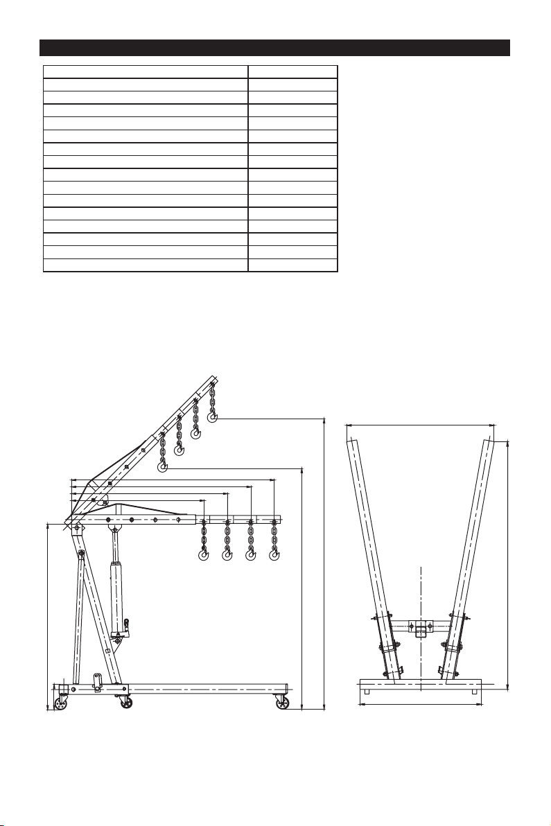
TECHNICAL SPECIFICATIONS
TECHNICAL SPECIFICATIONS
ItemD escription
Lifting Capacity Position 1 (P1) 0.5 Ton
Lifting Capacity Position 2 (P2) 1 Ton
Lifting Capacity Position 3 (P3) 1.5 Ton
Lifting Capacity Position 4 (P4) 2 Ton
Max. Lifting Height Min. Jib ext (H1) 71-1/4 inch
Max. Lifting Height Min. Jib ext (H2) 86-5/8 inch
Length of Jib Position 1 (L1) 35-7/16inch
Length of Jib Position 2 (L2) 42-1/8 inch
Length of Jib Position 3 (L3) 48-13/16 inch
Length of Jib Position 4 (L4) 55-1/2 inch
Height of Frame (A )7-1/2 inch
Length of Frame (B) 63-3/8 inch
Overall Height (C) 52-1/16 inch
Width of Frame Max (D) 39-3/8 inch
Distance Between Center of Rear Wheel (E) 29-1/2 inch
AC
H1
H2
P4
L1 L2 L3 L4
P3 P2
E
B
D
P1
)
4
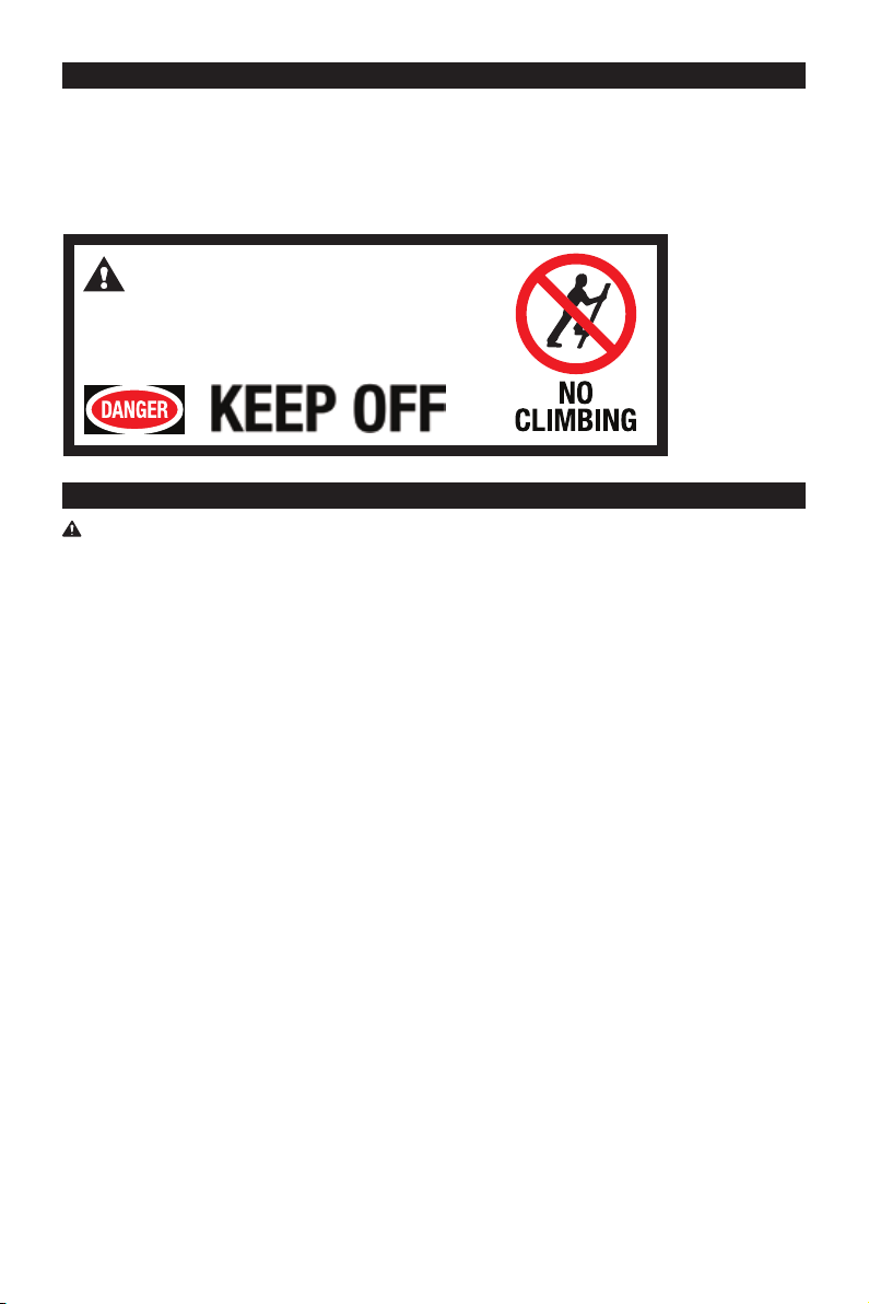
SAFETY MARKINGS
SAFETY
Always use Jack Stands!
Always follow safety precautions when installing and operating this equipment. Keep all decals on the unit
clean and visible. Before proceeding ensure that you fully understand and comprehend the full contents of
this manual. Failure to operate this equipment as directed may cause injury or death. The distributor is not
responsible for any damages or injury caused by improper use or neglect.
1. Study, understand, and follow all instructions before operating this device.
2. Do not exceed rated capacity.
3. Use only on hard, level surfaces, with less than 3 degrees of slope.
4. Before moving, lower the load to the lowest possible point.
5. Use only slings or chains with a rated capacity greater than the weight of the load being lifted.
6. Do not allow load to swing or drop violently while lowering or moving.
7. Center load prior to lifting.
8. No alterations shall be made to this product.
9. Make sure that boom is fully lowered before adding oil to unit reservoir.
10. Never use on a lawn mower or lawn tractor.
11. Do not rock the vehicle while working on or around equipment.
12. Equipment is design for lifting only, do not move or dolly crane when in use.
13. The following are not recommended for supporting on this equipment: Foundations, Homes, Mobile
Homes, Trailers, RV’s, Campers, nor Fifth Wheels, etc...
14. Do not use this crane for any use other than the manufacturer specied usage.
15. Failure to heed these markings may result in personal injury and/or property damage.
WARNING!
DO NOT CLIMB, HANG OR SWING.
MISUSE OF ENGINE CRANE COULD RESULT
IN A FALL THAT MAY RESULTIN SEVERE INJURY!
WARNING!

5
GENERAL SAFETY RULES
USE AND CARE
INSPECTION
GENERAL SAFETY RULES
IMPORTANT SAFETY CONSIDERATIONS
WARNING: Read and understand all instructions. Failure to follow all instructions listed below may result
in serious injury.
WARNING: The warnings, cautions, and instructions discussed in this instruction manual cannot
cover all possible conditions or situations that could occur. It must be understood by the operator
that common sense and caution are factors that cannot be built into this product, but must be supplied by
the operator.
CAUTION: Do not allow persons to operate or assemble this jack until they have read this manual and
have developed a thorough understanding of how the jack works.
• Do not modify the equipment in any way. Unauthorized modication may impair the function and/or safety
and could affect the life of the equipment. There are specic applications for which the equipment was
designed.
• Always check of damaged or worn out parts before using the equipment. Broken parts will affect the
equipment operation. Replace or repair damaged or worn parts, or missing parts immediately.
• Store idle. When equipment is not in use, store it in a secure place out of the reach of children. Inspect it for
good working condition prior to storage and before re-use.
• Not for use by children or people with reduced mental capacity.
• Do not use under the inuence of drugs or alcohol.
• Ensure children and other bystanders are kept at a safe distance when using equipment.
• Inspect the equipment carefully before each use. Ensure the equipment is not damaged, excessively worn,
or missing parts.
• Do not use the equipment unless it is properly lubricated.
• Using equipment that is not in good clean working condition or properly lubricated may cause serious injury.
• Inspect the work area before each use. Make sure it is free and clear of any potential hazards.
DO NOT OPERATE OR REPAIR THIS EQUIPMENT WITHOUT READING THIS MANUAL.
To maintain the equipment and user safety, the responsibility of the owner is to read and follow these
instructions.
• Inspect the equipment for proper operation and function.
• Keep instructions readily available for equipment operators.
• Make certain all equipment operators are properly trained; understand how to safely and correctly operate
the unit.
• Allow unit operation only with all parts in place and operating properly.
• Use only genuine replacement parts.
• Service and maintain the unit only with authorized or approved replacement parts; negligence will make the
equipment unsafe for use and void the warranty.
• Carefully inspect the unit on a regular basis and perform all maintenance as required.
• Store these instructions in the handle of your equipment.
• Keep all decals on the unit clean and visible.

6
GENERAL SAFETY INSTRUCTIONS
Position the Crane
Position the crane to only lift on the areas of the vehicle as specied by the vehicle manufacturer.
Do Not Overload Crane
Do not overload this crane beyond its rated capacity. Overloading this crane beyond its rated capacity can
cause damage to or failure of the crane.
Always Use on Hard Level Surfaces
This crane is designed only for use on hard level surfaces capable of sustaining the load. Use on unstable or
other possible loss of load.
Chock and Block (Stabilize)
Apply parking brake in vehicle before operating crane.
A chock is a wedge for steadying an object and holding it motionless, or for preventing the movement of a
wheel. Chock the wheel opposite the end being lifted.
Center Load before lifting.
Off-center loads and loads lifted when the crane is not level can cause loss of load or damage to the crane.
Do not raise or lower the vehicle unless tools, materials and people are clear.
When the lift is being lowered, make sure everyone is standing at least six feet away. Be sure there are no
tools or equipment left under or around the crane before lowering.
Always lower the Crane slowly.
DO NOT USE THE CRANE TO SUPPORT OR STABILIZE A LOAD.
Using the crane to support or stabilize a load may result in unexpected movement and result in serious injury,
being crushed and death. Always securely chock and block (stabilize) the load to be lifted. Never place any
part of the body under a raised load without properly chocking and supporting the load.
Wear ANSI-approved safety glasses and heavy duty work gloves during use.
Do not adjust the safety valve.
Stay alert. Use caution and common sense when operating crane. Do not use a crane when tired,
incoherent, dizzy, under the use or drugs or alcohol.
Training
Read this manual before use. Do not allow anyone who has not read this manual, and/or does not
understand the requirements, use the crane.
Spectators
Do not allow bystanders around the crane or under the load supported only by the crane. -Do not allow
anyone in the vehicle while the crane is in use. Keep all bystanders away from vehicle when in use.
Inspection
Inspect the crane carefully before each use. Ensure the crane is not damaged, excessively worn, or missing
parts. -Do not use the crane unless it is properly lubricated. -Using a crane that is not in good clean working
condition or properly lubricated may cause serious injury.
Additional Notes:
Save the receipt, warranty and these instructions.
Do not modify the crane in any way. Unauthorized modication may impair the function and/or safety and
could affect the life of the equipment. There are specic applications for which the crane was designed.
Always check for damaged or worn out parts before using the crane. Broken parts will affect the equipment
operation. Replace or repair damaged or worn parts immediately.
When crane is not in use, store it in a secure place out of the reach of children. Inspect it for good working
condition prior to storage and before re-use.
7
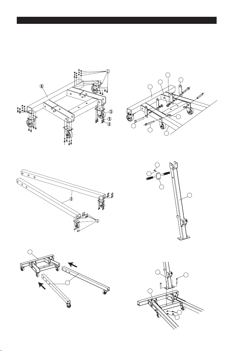
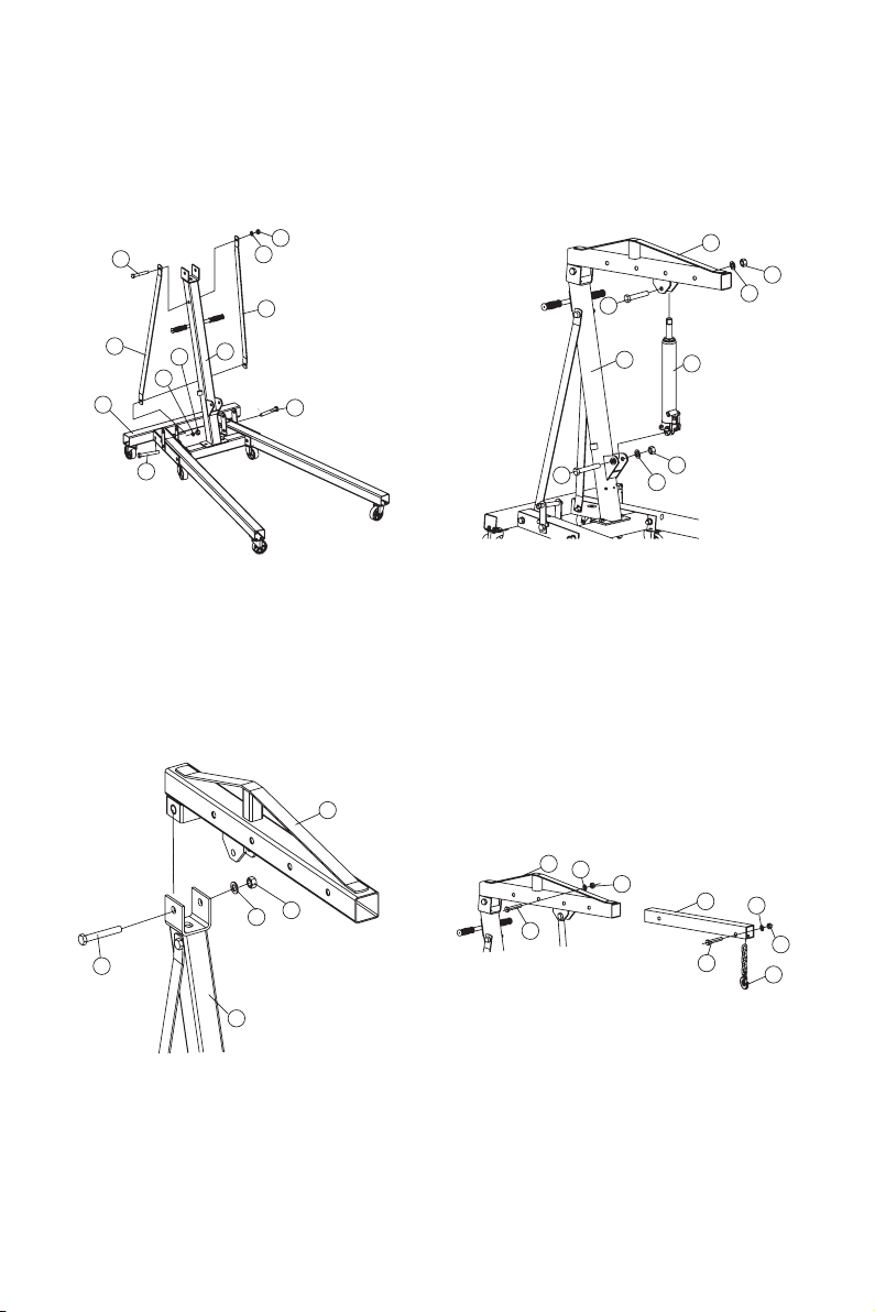
ASSEMBLY
1. Fasten the two larger rear caster wheels (No.1)
on the Base structure with Bolts, washers , spring
washers and nuts (Face bolts up when installing.)
2. Fasten the smaller two caster wheels (No.3)
on the Base structure with Bolts (No.4), spring
washers (No.5). (Face bolts up when installing.)
5. Fasten the guide plates (No.12), to the base frame
(No.6) and front legs (No.2) with bolts (No.11),
washers (No.13) and nuts (No.14). Lift one side
of the base to align the hole on the frame to the
hole on each front leg (No.2), then insert the Ring
Pins (No.10) into the hole, and insert the Cotter-
Pin (No.9) into the hole of the Ring Pins.
6. Use Bolts (No.4) and Spring Washers (No.5) to
fasten the Handle (No.29) to the Post (No.21).
7. Use two Bolts (No.19), washers (No.8) and Nuts
(No.7) to connect the bottom of the Post (No.21)
to the Base Frame (No.6).
3. Fasten the remaining larger two caster wheels
(No.1) on the front legs (No.2) with bolts, washers,
spring washers and nuts.
4. Slide the legs (No.2) into front of the base (No.6).
6
2
6
2
9
14
13
12
11 10
5
4
29
21
6
7
8
21 19
8
8. Use two Bolts (No.15), Washers (No.17) and Nuts
(No.18) to connect the lower ends of the Supports
(No.16) to the inside of the base (No.6). Then use
Bolt (No.28), Washer (No.22) and Nut (No.18)
to connect the top ends of the Supports to the
post (No.21), check to make sure the nuts were
tightened, and tighten the nuts in step 6.
10. Use Bolt (No.20), Washer (No.22) and Nut
(No.18) to fasten the lower end of the Long
Ram (No.27) to the Post (No.21). Then use
Bolt (No.32), Washer (No.22) and Nut (No.18)
to fasten the top of the Long Ram to the Boom
(No.33).
11.Slide the Boom Extension (No.35) into the Boom
(No.33) and use Bolt (No.34), Washer (No.22)
and Nut (No.18) to secure at the desired load
rating. Use Bolt (No.36), Washer (No.8) and Nut
(No.7) to attach the Hook and Chain (No.37) to
the end of the Boom Extension. (The boom has
four different load ratings; select desired rating
before use.)
9. Use Bolt (No.30), Washer (No.31) and Nut (No.14)
to attach the Boom (No.33) to the top of the Post
(No.21) , tighten Nut (No.14) so that the boom
(No.33)can rotate freely, do not over tightened
boom needs to be able to rotate freely.
6
28
18
18
22
16
15
15
17
16 21
20 22 18
27
21
32 22
18
33
33
31 14
21
30
8
7
34
33 22 18
35
36 37
9
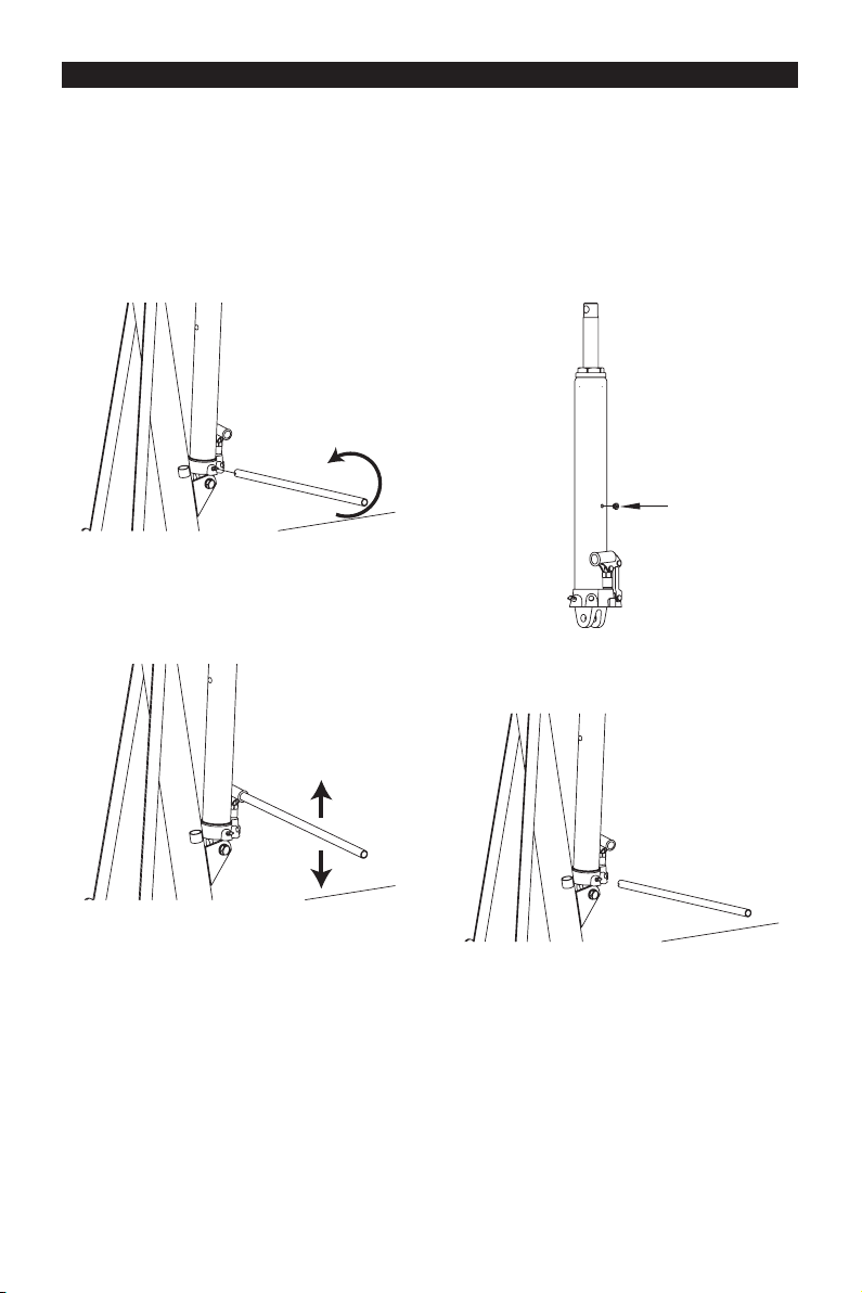
SYSTEM AIR PURGE PROCEDURE
IMPORTANT: BEFORE FIRST USE
Before initial use and over time it is possible that air will enter the hydraulic system, causing poor lifting
performance. Perform the following Air Purge Procedure to remove any air that may have been introduced
into the hydraulic system as a result of product shipment and handling. This step is to be completed without
any weight on the crane.
1. Turn release valve counterclockwise on full turn to
the open position.
3. With a at blade screwdriver, push the oil ll
plug slightly to the side to purge trapped air from
system. (Use caution not to tear or puncture the
oil plug.)
4. Turn release valve clockwise to the closed
position.
5. Crane is now ready for use. Check for proper
pump action.
2. Rapidly pump the handle 6-8 times. Leave handle
in down position to expose oil ll plug.
Oil Plug
10
OPERATING INSTRUCTIONS
BEFORE USE
1. Before using this product, read the owner's manual completely and familiarize yourself thoroughly with the
product and the hazards associated with its improper use.
2. Perform the air purge procedure. (See previous instructions for system purge procedure.)
3. Check and that the pump operates smoothly before putting into service.
4. Inspect before each use. Do not use if bent, broken or cracked components are noted.
IMPORTANT: It is possible for air to enter the hydraulic system, causing poor lifting performance. Purge any
air from the system by fully opening the release valve (turn handle counterclockwise as shown). Then while
holding the boom down, operate pump handle rapidly several times.
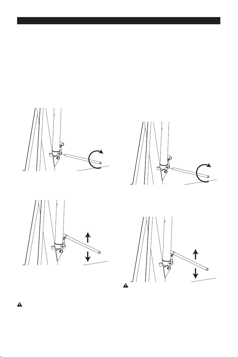
HYDRAULIC OPERATION RAISING THE CRANE
1. Familiarize yourself with the crane
2. Attach the handle piece, making sure to align with
lowering valve, turn CLOCKWISE until tight.
1. Block the vehicle’s wheels for lifting stability.
Secure the load to prevent inadvertent shifting and
movement.
2. Position the crane near desired lift point.
3. Set the Parking Brake in the vehicle.
4. Close the release valve by turning it clockwise
until it is rmly closed.
5. Before raising the load double check and verify
the load is centered and also has full contact with
the lifting point.
6. Pump handle to lift load. Continue to pump the
long ram handle to raise the load to the desired
height. After lifting, support the load appropriately.
3. Line up the handle to the handle socket located
on the side of the long ram, then insert the handle
inside the handle socket.
4. Secure the handle in place inside the handle
socket. Without any weight on the crane, cycle the
crane up and down several times to insure the
hydraulic system is operating properly. (Perform to
the Air Purge Procedure before rst use.)
THIS LONG RAM IS DESIGNED FOR LIFTING
PURPOSES ONLY, NOT FOR SUPPORTING
LOADS. DO NOT LOAD BEYOND ITS RATED
CAPACITY.
CAUTION:
NEVER WIRE, CLAMP OR OTHERWISE DISABLE
THE LIFT CONTROL VALVE TO FUCTION BY
ANY MEANS OTHER THAN BY USING THE
OPERATOR'S HAND. USE THE HANDLE
PROVIDED WITH THIS PRODUCT OR AN
AUTHORIZED REPLACEMENGT HANDLE TO
ENSURE PROPER RELEASE VAVLE OPERATION.
DO NOT USE EXTENSIONS ON ANY AIR HOSE
OR ON THE OPERATING HANDLE.
WARNING!

11
LOWERING THE CRANE
1. Raise load high enough to allow for clearance.
2. Grasp the handle rmly with both hands. Securely
hold on to the long ram handle so your hands do not
slip and ensure the release valve does not rapidly
lower.
3. Carefully open the Release Valve by slowly
turning the handle counterclockwise. (Do not allow
bystanders around the crane or under the load when
lowering the crane.
4. After removing crane from the load, lower to
lowest resting position to reduce exposure to rust
and contamination.
WARNING: USE EXTREME CAUTION WHEN
LOWERING THE CRANE. THE LONG RAM
HANDLE MAY TURN RAPIDLY. OPENING THE
RELEASE VALVE TOO FAST CAN CAUSE THE
CRANE TO LOWER RAPIDLY. FAILURE TO HEAD
THESE WARNINGS COULD CAUSE SERIOUS
INJURY OR DEATH.

12
MAINTENANCE INSTRUCTIONS
If you use and maintain your equipment properly, it will give you many years of service. Follow the
maintenance instructions carefully to keep your equipment in good working condition. Never perform any
maintenance on the equipment while it is under a load.
Inspection
You should inspect the product for damage, wear, broken or missing parts (e.g.: pins) and that all components
function before each use. Follow lubrication and storage instructions for optimum product performance.
Binding
If the product binds while under a load, use equipment with equal or a larger load capacity to lower the load
safely to the ground. After un-binding; clean, lubricate and test that equipment is working properly. Rusty
components, dirt, or worn parts can be causes of binding Clean and lubricate the equipment as indicated in
the lubrication section. Test the equipment by lifting without a load. If the binding continues contact Customer
Service.
Cleaning
If the moving parts of the equipment are obstructed, use cleaning solvent or another good degreaser to clean
the equipment. Remove any existing rust, with a penetrating lubricant.
Lubrication
This equipment will not operate safely without proper lubrication. Using the equipment without proper
lubrication will result in poor performance and damage to the equipment. Some parts in this equipment are not
self-lubricating inspect the equipment before use and lubricate when necessary. After cleaning, lubricate the
equipment using light penetrating oil, lubricating spray.
-Use a good lubricant on all moving parts.
-For light duty applications, use lubrication once a month.
-For heavy and constant application, weekly lubrication is recommended.
-NEVER USE SANDPAPER OR ABRASIVE MATERIAL ON THESE SURFACES!
Rust Prevention:
-Check rams and pump plungers on the power unit assemblies daily for any signs of rust or corrosion.
Without a load, lift the equipment as high as it goes and look under and behind the lifting points. If signs of
rust are visible, clean as needed.
How the Long Ram Operates
With release valve closed, an upward stroke of the long ram handle draws oil from the reservoir tank into
the plunger cavity. Hydraulic pressure holds the valve closed, which keeps the oil in the plunger cavity. A
downward stroke of the long ram handle releases oil into the cylinder, which forces the ram out. This raises
the hydraulic ram. When the ram reaches maximum extension, oil is bypassed back into the reservoir to
prevent an over extended ram stroke and possible damage to the long ram. Opening the release valve allows
oil to ow back into reservoir. This releases hydraulic pressure on the ram, which results in lowering the
hydraulic ram.
Storing the Crane
1. Lower the Lifting Arm.
2. Place the handle in the upright position.
3. Store in a dry location, recommended indoors.
Note: If the crane is stored outdoors, be sure to lubricate all parts before and after use to ensure the crane
stays in good working condition.

13
TO ADD OIL
TO REPLACE OIL
1. Open the Release Valve by slowly turning the
handle counterclockwise and lower ram to it’s lowest
position.
2. Remove the oil plug.
3. With long ram in the vertical position Fill the oil
case until oil level is just beneath the lower rim of the
oil ll hole.
5. Perform the Air Purge Procedure.
*SEE ASSEMBLY IMAGE FOR OIL RESEVOIR
LOCATION.
1. Open the Release Valve by slowly turning the
handle counterclockwise and lower ram to it’s lowest
position.
4. Replace the oil plug.
Oil Plug
Oil Plug
Oil Plug

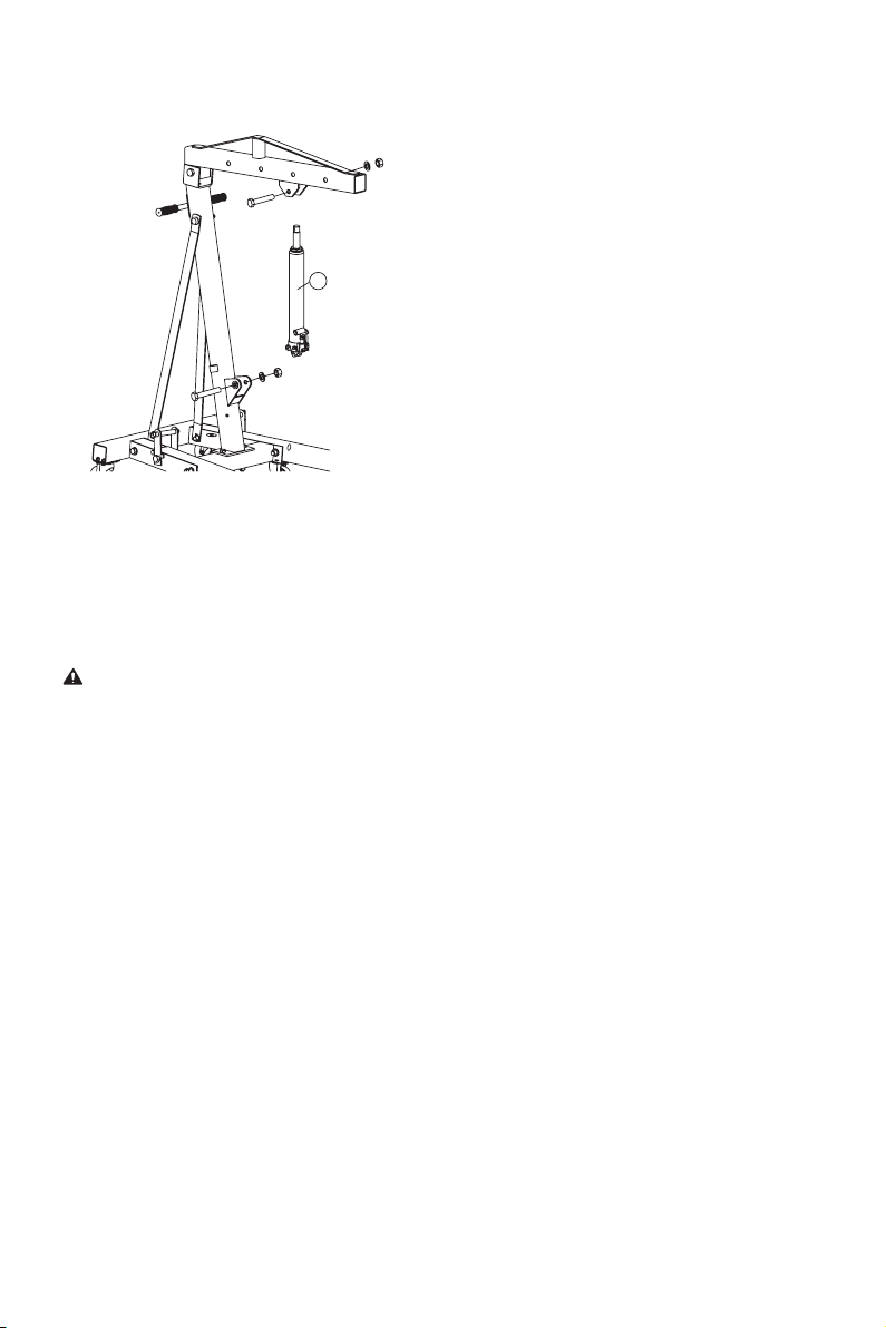
14
2. Unscrew and remove bolts and nuts as show
in image below and remove the long ram (No.27).
Remove the long ram (27).
Note: Use caution when removing long ram.
3. Remove the oil plug.
4. Turn the long ram on its side to drain old oil from
the oil ll hole.
5. Position the long on level ground in the vertical
position and keep hydraulic ram in the lowered
position.
6. Fill the oil case until oil level is just beneath the
lower rim.
KEEP DIRT AND OTHER MATERIAL CLEAR
WHEN POURING.
7. Replace the oil plug.
27
Oil Plug
Oil Plug
Oil Plug
15
8. Re-Install long ram (27) into frame.
(See Step 2 and 3.)
9. Tighten Hardware Removed.
10. Perform the Air Purge Procedure.
ADDITIONAL WARNINGS:
• DO NOT USE MOTOR OIL IN THE CRANE.
• ONLY USE ANTI-FOAMING JACK OIL.
• ALWAYS USE A GOOD GRADE HYDRAULIC JACK OIL.
• DO NOT USE HYDRAULIC BRAKE FLUID, ALCOHOL, GLYCERINE, DETERGENT, MOTOR OIL OR
DIRTY OIL.
• USE OF A NON-RECOMMENDED FLUID CAN CAUSE DAMAGE TO A CRANE.
• AVOID MIXING DIFFERENT TYPES OF FLUID AND NEVER USE BRAKE FLUID, TURBINE OIL,
TRANSMISSION FLUID, MOTOR OIL OR GLYCERIN. IMPROPER FLUID CAN CAUSE PREMATURE
FAILURE OF THE CRANE AND THE POTENTIAL FOR SUDDEN AND IMMEDIATE LOSS OF LOAD.
• DISPOSE OF HYDRAULIC FLUID IN ACCORDANCE WITH LOCAL REGULATIONS.
ADDITIONAL LUBRICATION:
1. Periodically check the pump piston and ram for signs of rust or corrosion. Clean as needed and wipe with
an oil cloth. NEVER USE SANDPAPER OR ABRASIVE MATERIAL ON THESE SURFACES!
2. When not in use, store the Crane with pump piston and ram fully retracted.
ADDITIONAL WARNINGS:
27
16
29
30 22
18
28
15 16
17 18
14 13
8
76
9
34
5
2
10
11
1
1
12
19
20 21
16
22
19 18
17 15
23
24 25
27
26
32
34
35
38 37
36 7
8
33
22
22
18
18
18
31 14
45
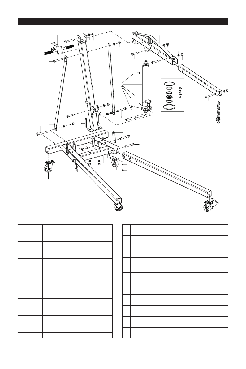
ASSEMBLY DIAGRAM
No. Part Description Qty
1 T32002.6 Swivel caster 3-1/2“ 4
2 T32002X.4 Front leg 2
3 T32002.7 Swivel caster 3“ 2
4 GB5781 Hex head bolt M8x10mm 12
5 GB93 Spring washer M8 28
6 Frame base 1
7 Nut M14 3
8 Washer M14 3
9 Hitch Pin Ø2x49mm 2
10 T32002.2 Quick-release pin Ø18x125mm 2
11 Hex head bolt M18x120mm 2
12 T32002X-1 Connector plate brackets 4
13 Spring washer M18 2
14 Nut M18 3
15 Hex head bolt M16x110mm 2
16 T32002X-2 Support strap 2
17 Spring washer M16 3
18 Nut M16 6
19 Hex head bolt M14x100mm 2
No. Part Description Qty
20 Hex head bolt M16x90(metric-class 8.8) 1
21 Main column assembly 1
22 Washer M16 4
23 QYL5-23 Pump handle 1
24 QYL8-25A(ASM) Release Valve assembly 1
25 GB308-6 Steel ball Ø6mm 1
26 T815016L.3-
13(ASM) Oil Plug 1
27 T30506X.0 Hydraulic ram 1
28 GB5780 Hex head bolt M16x100mm 1
29 T32002C.8(ASM) Pull handle 1
30 Hex head bolt M18x110mm 1
31 Washer M18 1
32 Hex head bolt M16x75mm(metric-class 8.8) 1
33 T32002X.3 Main boom 1
34 Hex head bolt M16x90mm 1
35 T32002X-3 Extended boom 1
36 Hex head bolt M14x75mm(metric-class 8.8) 1
37 T32002.5 Chain sling assembly 1
38 T30506X.MF Seal Kit 1

17
TROUBLESHOOTING
JACK
WILL
NOT
LIFT
LOAD
JACK
WILL
NOT
HOLD
LOAD
JACK
WILL
NOT
LOWER
POOR
JACK
LIFTING
WILL NOT
LIFT TO
FULL
EXTENSION
CAUSES AND SOLUTIONS
Release valve is not completely closed
(Turn handle clockwise).
Weight Capacity Exceeded.
Air is in the hydraulics.
Purge air from system.
Low oil level. Add oil as required.
Oil reservoir is overlled.
Drain excessive oil.
Lubricate moving parts.
Jack is binding or foreign obstruction
Power unit malfunctioning.
Replace the power unit.
X XX
X
X X
X X XX
X X X
X
X
Safe Operating Temperature is between 40°F – 105°F (4°C - 41°C)
WARRANTY NOTICE
WARRANTY INFORMATION
This product is covered under a 1-year limited warranty when used as recommended. Only those items listed
with a Part # are available for purchase. For assistance with the operation or the availability of replacement
parts, contact our Parts and Warranty Department at 1-888-44-TORIN (1-888-448-6746). Please have
available a copy of your receipt, the model number of the product, serial number, and specic details
regarding your question.
Not all equipment components are available for replacement; illustrations provided are a convenient reference
of location and position in the assembly sequence.
The manufacturer reserves the rights to make design changes and or improvements to product lines
and manuals without notice.
We want to know If you have any concerns with our products. If so, please call toll-free for Immediate
assistance. For additional web customer support help inquiries visit the Customer Service section at: http://
www.torin-usa.com.

18
TORIN ONE YEAR LIMITED WARRANTY
Torin Inc.® has been producing quality automotive repair and maintenance products since 1968. All products
sold are felt to be of the highest quality and are covered by the following warranty:
With proof of purchase for a period of one year from the date of that purchase, the manufacturer will repair or
replace, at its discretion, without charge, any of its products or parts thereof which fail due to a defect in
material or workmanship. This warranty does not cover damage or defects caused by improper use, careless
use or abuse of the equipment. This warranty does not cover parts normally considered to wear out or be
consumed in the normal operation of the equipment. Except where such limitations and exclusions are
specically prohibited by applicable law, (1) the CONSUMERS SOLE AND EXCLUSIVE REMEDY SHALL BE
THE REPAIR OR REPLACEMENT OF DEFECTIVE PRODUCTS AS DESCRIBED
ABOVE, and (2) THE MANUFACTURER SHALL NOT BE LIABLE FOR ANY CONSEQUENTIAL OR
INCIDENTAL DAMAGE OR LOSS WHATSOEVER, and (3) THE DURATION OF ANY AND ALL
EXPRESSED AND IMPLIED WARRANTIES, INCLUDING, WITHOUT LIMITATION, ANY WARRANTIES OF
MERCHANTABILITY AND FITNESS FOR A PARTICULAR PURPOSE, IS LIMITED TO A PERIOD OF ONE
YEAR FROM DATE OF PURCHASE. Product alteration in any manner by anyone other than us, with the sole
exception of alterations made pursuant to product instructions and in a workman like manner. You
acknowledge and agree that any use of the product for any purpose other than the specied use(s) stated in
the product instructions is at Your own risk.
Always check for damaged or worn out parts before using any product. Broken parts will affect the equipment
operation. Replace or repair damaged or worn parts immediately. Do not modify the product in any way.
Unauthorized modication may impair the function and/or safety and could affect the life of the equipment.
There are specic applications for which products are designed and tested during production. Manufacturer
provided warranted items are not authorized to be repaired by anyone other than the manufacturer or
manufacture approved repair person. Distributor does not have authorization to amend these statements. You
acknowledge and agree that any modication of the product for any purpose other than manufacturer
completed repairs is at your own risk. Before using this product, read the owner's manual completely and
familiarize yourself thoroughly with the product and the hazards associated with its improper use.
IMPORTANT: BEFORE FIRST USE on any Lift verify that a daily inspection has been completed and that all
components are in the proper working order.
This limited warranty gives you specic legal rights, and you also may have other rights, which vary from
state to state. Some states do not allow limitations or exclusions on implied warranties or incidental or
consequential damages, so the above limitations may not apply to You. This limited warranty is governed by
the laws of the State of California, without regard to rules pertaining to conicts of law. The state courts
located in San Bernardino County, California shall have exclusive jurisdiction for any disputes relating to this
warranty.
Manufacturer reserves the rights to make design changes and or improvements to this product lines and
manual without notice. We at Torin have taken every effort to ensure complete and accurate instructions have
been included in this manual. However, possible product updates, revisions and or changes may have
occurred since this printing. Torin Inc. reserves the right to change specications without incurring any
obligation for equipment previously or subsequently sold. Not responsible for typographical errors.
Alternately Customer Service can be reached through www.torin-usa.com or via email at
Not all equipment components are available for replacement, but are illustrated as a convenient reference of
location and position in the assembly sequence. Contact Customer Service for equivalent component. When
you contact us, please have your Product’s Model number, Serial Number and Description ready so that we
may help you efciently. This information can be found on a sticker on the product.
For any warranty support or if your Torin® equipment is not functioning properly contact
Torin® Customer Service directly by telephone at 1-888-44-TORIN (1-888-448-6746)
8:00am – 5:00pm Pacic Time, Monday – Friday
www.torin-usa.com Made in China

19
GUIDE D’UTILISATION
GRUE POUR MOTEUR
HYDRAULIQUE - 2 TONNES
Article : T32001
Version 20170306
Questions, problèmes, pièces manquantes? Avant de retourner voir votre fournisseur, appelez notre service à
la clientèle au 1-888-44-TORIN (1-888-448-6746) entre 8 heures et 17 heures, HNP, du lundi au vendredi.
Lisez attentivement et comprenez toutes les DIRECTIVES DE MONTAGE ET DE FONCTIONNEMENT avant
l’utilisation. Vous pouvez subir des blessures graves si vous ne vous conformez pas à ces règles et autres
précautions de sécurité.
AVERTISSEMENT!

20
IMPORTANT
Avant de commencer, enregistrez ce produit.
Pour référence future, enregistrez le nom de modèle, le numéro, la date de fabrication et la date d’achat du
produit. Vous pouvez trouver ces renseignements sur le produit.
Nom de modèle _______________________
Numéro de modèle _______________________
Date de fabrication _______________________
Date d’achat _______________________
RESPONSABILITÉ DU PROPRIÉTAIRE OU DE L’UTILISATEUR
UTILISATION PRÉVUE
NE PAS UTILISER OU RÉPARER CE PRODUIT SANS AVOIR LU LE PRÉSENT MANUEL.
Lisez et suivez les directives de sécurité. Conservez ces directives à la disponibilité des opérateurs. Assurez-
vous que tous les opérateurs sont bien formés et savent comment utiliser le produit correctement et en toute
sécurité. En continuant, vous convenez que vous comprenez complètement le contenu du présent manuel.
Le produit peut causer des blessures ou provoquer la mort si vous n’utilisez pas le produit dans le but pour
lequel il a été conçu. Le fabricant n’est pas responsable des dommages ou blessures provoquées par une
utilisation inappropriée ou par négligence. Ne faites fonctionner le produit que si toutes les pièces sont en
place et fonctionnent de manière sécuritaire. N’utilisez que des pièces de rechange authentiques. Effectuez
l’entretien de ce produit uniquement avec des pièces de rechange autorisées ou approuvées; la négligence
rendra l’utilisation du produit dangereuse et annulera la garantie. Inspectez régulièrement et avec soin
le produit et effectuez tout l’entretien nécessaire. Conservez ces directives dans un endroit protégé sec.
Conservez propres et visibles tous les autocollants sur le produit. Ne modiez pas ou n’utilisez pas le produit
pour une application autre que celle pour laquelle il a été conçu. Pour toute question relative à une application
particulière, N’utilisez PAS le produit avant d’avoir communiqué avec le distributeur ou le fabricant an de
déterminer si cela peut se faire.
Pour toutes questions d’ordre technique, appelez au 1-888-44-TORIN (1-888-448-6746).
Ce cric pour poids lourd possède une pompe hydraulique à piston unique qui soulève sans effort le bras de
levage. Les pare-poussière et les joints racleur du piston de la pompe protègent le circuit hydraulique des
contaminants. Le cric comporte un circuit de dérivation par soupape de surcharge an d’éviter d’endommager
le cric et de causer des blessures à l’utilisateur. Son encombrement réduit permet son utilisation dans des
espaces clos. Il se place facilement sous des véhicules surbaissés. Le cric est conforme aux normes de
sécurité ASME PASE.
Table of contents
Languages:
Other Torin BIG RED Construction Equipment manuals


