Torin QJY-S3 Quick start guide

QJY-S3
Scissor vehicle lift
Original Operation Manual
IMPORTANT SAFETY INSTRUCTIONS SAVE THESE INSTRUCTIONS
PLEASE READ THE ENTIRE CONTENTS OF THIS MANUAL PRIOR TO INSTALLATION AND
OPERATION. BY PROCEEDING WITH LIFT INSTALLATION AND OPERATION YOU AGREE
THAT YOU FULLY UNDERSTAND AND COMPREHEND THE FULL CONTENTS OF THIS
MANUAL. FORWARD THIS MANUAL TO ALL OPERATORS. FAILURE TO OPERATE THIS
EQUIPMENT AS DIRECTED MAY CAUSE INJURY OR DEATH


3
Content
Chapter 1 Packing, transport and storage.........................................................................................4
1.1Package ................................................................................................................................4
1.2 Transport .............................................................................................................................4
1.3 Storage ................................................................................................................................5
1.4 Opening...............................................................................................................................5
Chapter 2 Descripon of the machine ..............................................................................................5
2.1 Introducon ........................................................................................................................5
2.2 Intend use............................................................................................................................6
2.3 Layout dimension................................................................................................................7
2.4Technical parameter.............................................................................................................8
Chapter 3 Safety cauon...................................................................................................................8
3.1 General warnings ................................................................................................................8
3.2 Safety device....................................................................................................................9
3.3 Risk list.................................................................................................................................9
3.4 Warning labels...................................................................................................................11
Chapter 4 Installaon......................................................................................................................11
4.1 Tools required....................................................................................................................11
4.2 Selecng site .....................................................................................................................11
4.3 Floor requirements............................................................................................................11
4.4 Hydraulic system connecon ............................................................................................11
4.5Electrical system connecon............................................................................................113
Chapter 5 Adjustment.....................................................................................................................12
5.1Start....................................................................................................................................13
5.2Bleeding .............................................................................................................................14
5.3Checks no load ...................................................................................................................14
5.4Check with load..................................................................................................................14
Chapter 6 Operaon instrucon.....................................................................................................15
Chapter 7 Maintenance ..................................................................................................................16
Chapter 8 Trouble shoong.............................................................................................................17
Chapter 9 Disposal of used oil.........................................................................................................19
Chapter 10 Machine demolion .....................................................................................................19
Appendix .........................................................................................................................................19
1 Hydraulic diagram ................................................................................................................21
2 Exploded drawing
…………………………………………………………………22
4
Chapter 1 Packing, transport and storage
ALL PACKING, LIFTING, HANDLING, TRANSPORT AND UNPACKING ORERATIONS ARE TO BE
PERFORMED EXCLUSIVELY BY EXPERT PERSONNEL WITH KNOWLEDGE OF THE LIFT AND THE
CONTENTS OF THIS MANUL.
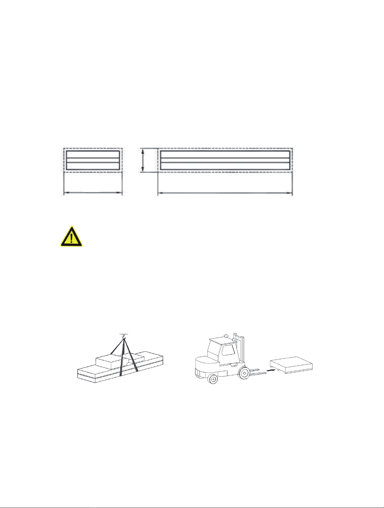
1.1Package
The dimension of package, please see below, and the package weight is 939.8Lbs,
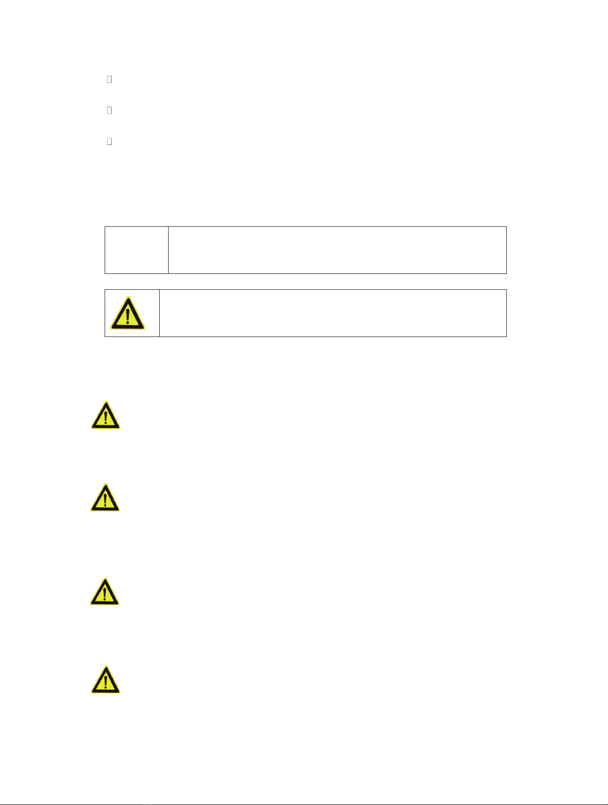
1.2 Transport
Packing can be lied or moved by litrucks, cranes or bridge cranes. In case of
slinging, a second person must always take care of the load, in order to avoid
dangerous oscillaons.
During loading and unloading operaon, goods must be handled by vehicles or ships. At the
arrival of the goods, verify that all items specied in the delivery notes are included. If nding
missing parts, possible defects or damage due to transport, one should examine damaged
cartons according to ‘Packing List’ to verify the condion of damaged goods and missing parts,
also the person in charge or the carrier must be immediately informed. The machine is heavy
goods! Don’t take manpower load and unload and transporng way into consideraon, the safety
of working is important. Furthermore, during loading and unloading operaon goods must be
handled as shown in the picture
Handled by crane
Handled by fork-litruck
1.3 Storage
-The machine equipment should be stocked in the warehouse, if stocked outside should do the
disposal well of waterproof.
-Use box truck in the process of transport, use container storage when shipping.
-The temperature for machine storage: -25ºC-- 55ºC
44.4" 103.5"
9"

5
1.4 Opening
When the crates arrive, check that the machine has not been damaged during transport and that
all parts listed are present. The crates must be opened using all possible precauonary measure
to avoid damaging the machine or its parts. Make sure that parts do not fall from the crate during
opening.
Chapter 2 Descrip�on of the machine
2.1 Introduc
Scissor-type Lier adopts the scissor-type mechanical structure; ulize the hydraulic
pressure to produce the liing power. The air pressure controls the lock and
loosening of the execu components. The mechanical lock could insure the
security and the hydraulic balance valve adjust the liing at level. It possesses many
advantages, such as simple structure, advanced technology, easy operaon, and
safety. It is especially suitable for high precision wheel alignment and Auto’s repair
and maintenance. The features as below:
1)The minimum height only 180mm( 7" ), ground installa
2)Pressure control safety mechanical lock assure safety operaon
2.2 Intend use
This scissor vehicle lican livarious vehicles which weight is less than 5000Lbs
5000Lbs
. And
it is suitable for vehicle test, repair, maintenance and care.
This liis designed to livehicles, not for other usage.
Forbid to use for washing and spraying vehicles!
Forbid to livehicle which weight is over
Forbid to park car.
Suggested minimum height to run this machine is 250~280mm(9.84"~11.02")

6
2.3 Layout dimension( metric:mm )

7
2.4 Technical parameter
Model type QJY-S3
Capacity
5000Lbs
Max. lifting height
1400mm / 55.1"
Platform length
1800mm / 70.8"
Platform width 1000mm / 39.3"
Lifting time ≤50s
Descent time ≤35s
Whole machine length 2550mm / 100.4"
Whole machine width 1476mm / 58.1"
Gross weight
Net weight
426.3kg / 939.8Lbs
Power supply 220V/380V
Power
2.2 KW
Noise
≤
70dB
Installation place
Indoors
Chapter 3 Safety cau�on
Read this chapter carefully and completely because it contains important information for
the safety of the operator and the person in charge of maintenance.
The lift has been designed and built for lifting vehicles and making them stand
above level in a closed area any other use is forbidden.
The manufacturer is not liable for possible damages to people, vehicles or
objects resulting from an improper or unauthorized use of the lift.
For operator and people safety, a square space for a safety area at least 39.3" free away
from the lift must be vacated during lifting and lowering. The lift must be operated only
from the operator’s control site in this safety area.
Operator’s presence under the vehicle, during working, is only admitted when the vehicle
is lifted and the safety lock is engaged.
Never use the lift when safety devices are off-line. People, the lift and the
vehicles lifted can be seriously damaged if these instructions are not followed.
3.1 General warnings
The operator and the person in charge of maintenance must follow accident-prevention
laws and rules in force in the country where the lift is installed.
They also must carry out the following:
Neither remove nor disconnect hydraulic, electric or other safety devices;
Carefully follow the safety indications applied on the machine and included in the
manual;
Observe the safety area during lifting;
Net weight 411.2kg / 906.5Lbs
8
Be sure the motor of the vehicle is off, the gear engaged and the parking brake put
on;
Be sure only authorized vehicles are lifted without exceeding the maximum lifting
capacity;
Verify that no one is on the arms during lifting or standing.
3.2 Safety device
To avoid overloading and possible breaking, the following safety devices have been used:
A maximum pressure valve is placed inside the hydraulic unit to prevent excessive
weight.
The maximum pressure valve has been preset by the manufacturer to a
proper pressure. DO NOT try to adjust it to overrun the rated lifting
capacity.
A mechanical safety mechanism is built inside each side with automatic engagement.
It is strictly forbidden to modify any safety device. Always ensure the
safety device for proper operation during the service.
3.3 Risk list
Risks for personnel
This heading illustrates potential risks for the operator, maintenance fitter, or any
other person present in the area around the lift, result from incorrect use of the
lift.
Risk of crushing
Possible if the operator controlling the lift is not in the specified position at the
control panel. When the platforms (and vehicle) are lowering the operator must
never be partly or completely underneath the movable structure. Always remain
in the control zone.
Risk of crushing (personnel)
When the platforms and the vehicle are lowering, personnel are prohibited from
entering the area beneath the movable parts of the lift. The lift operator must not
start the maneuvers unit it has been clearly established that there are no person
in potentially dangerous positions.
Risk of impact
Caused by the parts of the lift or the vehicle that is positioned at head height.
When, due to operational reasons, the lift is stopped at relatively low elevations
personnel must be careful to avoid impact with parts of the machine not marked
with special colors.
Risk of vehicle moving
9
Cause by operations involving the application of force sufficient to displace the
vehicle. In the case of large or particular heavy vehicles, sudden movement could
create an unacceptable overload or uneven load sharing. Therefore, before lifting
the vehicle and during all operations on the vehicle, make sure that it is properly
topped by the hand brake.
Risk of vehicle falling from lift
This hazard may arise in the case of incorrect positioning of the vehicle on the
platforms, incorrect stopping of the vehicle, or in the case of vehicles of
dimensions that are not compatible with the capacity of the lift.
Never attempt to perform tests by driving the vehicle while it is on the platforms
Never leave objects in the lowering area of the movable parts of the lift.
Risk of slipping
Cause by lubricant contamination of the floor around the lift. The area beneath
and immediately surrounding the lift and also the platforms must be kept clean.
Remove any oil spills immediately. When the lift is fully down, do not walk over
the platforms or the cross-pieces in places that are lubricated with a film of
grease for functional requirements. Reduce the risk of slipping by wearing safety
shoes.
Risk of electric shock
Risk cause by electric shock in areas of the lift housing electrical wiring.
Do not use jets of water, steam solvents or paint next to the lift, and take special
care to keep such substances clear of the electrical control panel.
Risks related to inappropriate lighting
The operator and the maintenance fitter must be able to assure that all the areas
of the lift are properly and uniformly illuminate compliance with the laws in force in
the place of installation.
Risk of component failure during operation
The manufacturer has used appropriate materials and construction techniques in
relation to the specified use of the machine in order to manufacture a reliable and
safe lift. Note however, that the lift must be used in conformity with manufacturer’s
prescriptions, and the frequency of inspections and maintenance works
recommended.
Risk related to improper use
Persons are not permitted to stand or sit on the platforms during the lift
maintenance or when the vehicle is already lifted.
The handling of safety devices is strictly forbidden.
Never exceed the maximum carrying capacity of the lift, make sure the vehicles to be lifted
10
have no load.
It is therefore essential to adhere scrupulously to all regulations regarding use,
maintenance and safety contained in this manual.
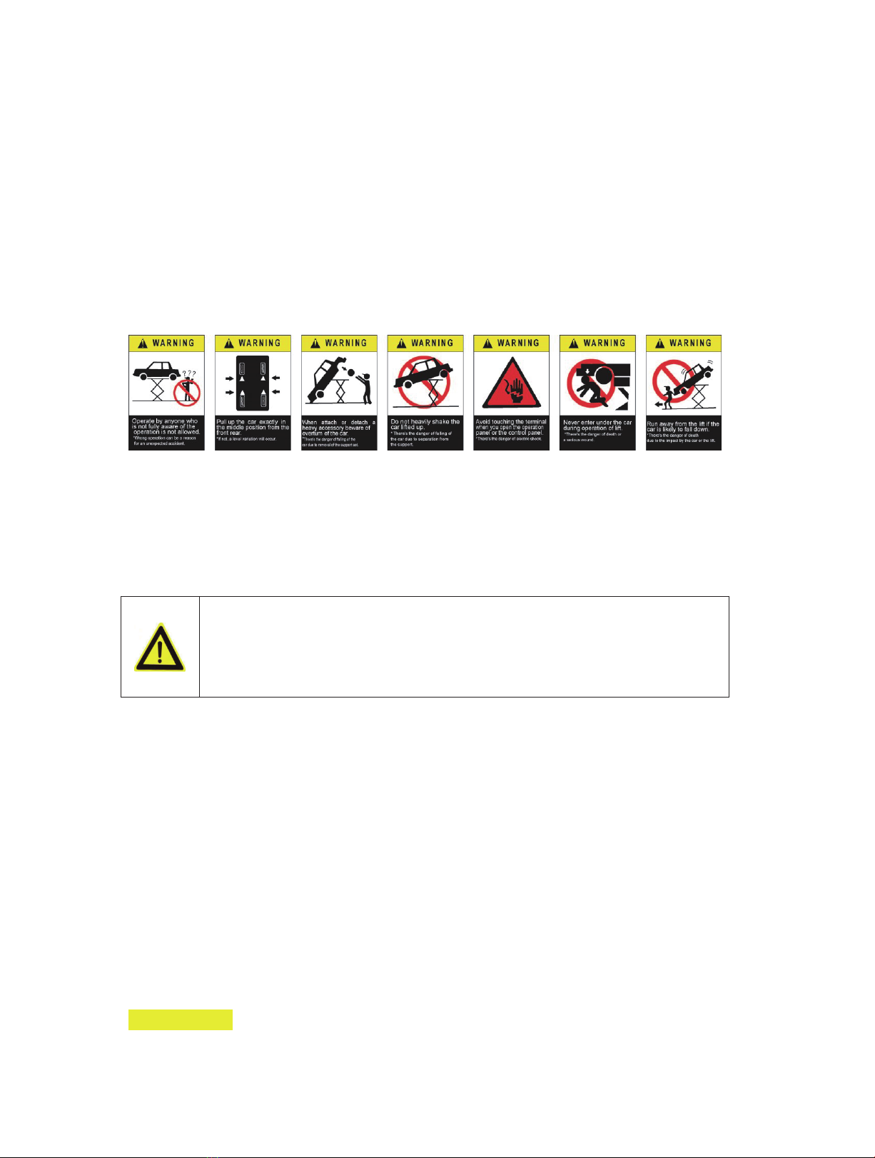
3.4 Warning labels
All safety warning signs displayed on the machine are with the purpose to draw the
operator’s attention to dangerous or unsafe situations. The labels must be kept clean and
they have to be replaced if detached or damaged. Read the meaning of the labels
carefully and memorize it.
Chapter 4 Installa�on
Only skilled technicians, appointed by the manufacturer, or by authorized
dealers, must be allowed to carry out installation. Serious damage to people
and to the lift can be caused if installations are made by unskilled personnel.
Always refer to the exploded views attached during installation
4.1 Tools required
Rotary Hammer Drill or Similar
3/4” Masonry Bit
Hammer 4 Foot Level
Medium Pipe Wrench
Crow Bar
Open-End Wrench Set: SAE/Metric
Chalk Line
Socket And Ratchet Set: SAE/Metric Crow Bar
Hex-Key / Allen Wrench Set
Medium Flat Screwdriver
Tape Measure: 25 Foot Minimum Needle Nose Pliers
Important noce
These instrucons must be followed to insure proper installaon and operaon of your li. Failure
to comply with these instrucons can result in serious bodily harm and void product warranty.
Manufacturer will assume no liability for loss or damage of any kind, expressed or implied,

11
resulng from improper installaon or use of this product. Please read enre manual prior to
installaon
4.2 Selecng site
Before installing your new lift, check the following.
1. LIFT LOCATION: Always use architectural plans when available. Check the layout
dimension against the floor plan requirements making sure that adequate space is
available.
2. OVERHEAD OBSTRUCTIONS: The area where the lift will be located should be free of
overhead obstructions such as heaters, building supports, electrical lines etc.
3. DEFECTIVE FLOOR: Visually inspect the site where the lift is to be installed and check
for cracked or defective concrete.
4. Your new scissor lift is designed for INDOOR INSTALLATION ONLY.
4.3 Floor requirements
The lift MUST be installed on 3000 PSI concrete with the minimum thickness 150mm(5.9") and
an extension of at least 1.5m(59") from anchoring points. New concrete must be adequately
cured by at least 20 days minimum.
DANGERS
DO NOT install or use this lift on any asphalt surface or any surface other than concrete.
DO NOT install or use this lift on expansion seams or on cracked or defective concrete.
DO NOT install or use this lift on a second / elevated floor without first consulting building
architect.
4.4 Hydraulic system connon
Connect hydraulic hoses.
Tightngs thoroughly.
4.5 Electrical system connec
Circuit wiring must be done by a professional electrician
Make sure power supply voltage is the same as the lirequirement
Ensure the phase connecon is correct the wrong wiring will burn out the
motor which is not in the scope of warranty. Power unit much be keep dry
According to the circuit wiring diagram, connect the wire with control box.

12
Chapter 5 Adjustment
5.1Start
Make sure all pins and bolts to insure proper mounng
Make sure the electrical system feeding voltage is equal to that specied in the
nameplate on the motor
Make sure the electric connecons are in compliant with the electrical diagram.
Make sure no leakage or blow-up in hydraulic line
Make sure the working area is free from people and objects
Grease sliding seats of blocks placed under plaorms and on bases
Pour oil in the tank (about 5 liters more then one
5.2Bleeding
Raising the lislowly by pressing UP buon un cylinders boom out and the
listops. DO NOT connue pressing buon aer lireaches full height. Damage
to motor can occur if connued.
Cylinders may jump upon ini start up which is normal due to trapped air
inside the hydraulic lines. In case that the licannot be raised upon inial start
up due to trapped air inside the pump: unloose the maximum pressure valve,
in-push the UP buon and reghten the valve aer trapped air has escaped,
then raise the liat full height.
Lower the licompletely.
Repeat raise and lower the licompletely at least 3 mes to equalize the oil
pressure in each cylinder.
5.3Checks no load
Carry out two or three complete cycles of lowering and liing and check:
•the safety devices for proper operaon
•proper oil level in the tank
•no leakage and blow-by in hydraulic line and pneumac line
•cylinder for proper opera
•the lifor reaching its maximum height
5.4Check with load
WARNING: Please follow carefully the instrucons in the coming paragraph for avoiding damages
on the li.
Carry out two or three complete cycles of lowering and liing and check:
Repeat the 5.3 secon , and check no strange noise during liing and lowering

13
Chapter 6 Opera�on instruc�on
Lioperaon by authorized personnel over 18 years only.
Apply the parking brake aer posioning the vehicle on the li.
Do not allow anyone to stay in liarea during raising and lowering cycles. Closely
watch the vehicle and the liduring raising and lowering cycles.
Observe the rated load capacity and load distribuon.
Do not allow anyone to climb on lior stay inside vehicle.
Aer raising the vehicle briefly, stop and check adapters for secure contact.
Make sure the vehicle doors are closed during raising and lowering cycles.
In case of defects or malfuncons such as jerky limovement or
deformaon of the superstructure, support or lower the liimmediately.
Turn offthe power. Contact qualified service personnel.
6.1 To raise the li
Position the vehicle at the centre of the platform. Check tomake sure that the vehicle
is secured.
Place the pads in the positions
Set Power Switch to on position
Press UP toraise the vehicle
To rest the lift in standing position at the desired height by releasing UP button.
Always ensure that the lift rests on the safety before any attempt is made to work on
or near the vehicle.
14
6.3 To lower the li
Be sure the safety area is free of people and objects;
Raise the lift a little bit by pushing UP button to clear off the safety;
Press unloading handle on the power unit to lower the lift.
Lower the lift completely
Chapter 7 Maintenance
Turn off and lock the main switch before servicing the lift.
The maintenance intervals indicated below apply to average workshop use. The
lift should be inspected more frequently for severe use applications.
Only trained personnel who knows how the lift works must be allowed to service
the lift.
To service properly the li, the following has to be carried out:
Use only genuine spare parts as well as equipment suitable for the work required;
Follow the scheduled maintenance and check periods shown in the manual;
Discover the reason for possible failures such as too much noise, overheang, oil blow-by,
etc.
Refer to documents supplied by the dealer to carry out maintenance:
Funconal drawing of the electric and hydraulic equipment
Exploded views with all data necessary for spare parts ordering
List of possible faults and relevant soluons.
7.1 Ordinary maintenance
The lihas to be properly cleaned at least once a month using self-cleaning clothes.
Lubricate all pivot pins at least once a week. Be sure the rod of the hydraulic cylinders
is always clean and not damaged since this may result in leakage from seals and, as a
consequence, in possible malfuncons.
7.2 Periodic maintenance
Every 3 months
Hydraulic
circuit
Check oil tank level; refill with oil, if needed;
Check the circuit for oil leakage.
Check seals for proper conditions and replace them, if necessary;
Foundation
bolts
Check bolts for proper tightening
Hydraulic
pump
Verify that no noise changes take place in the pump when running an
d
check fixing bolts for proper tightening
Safety systemCheck safety devices for proper operation

15
Every 6 months Oil Check oil for contamination or ageing. Contaminated oil is
the main reason for failure of valves and shorter life of gears pumps
Every 12 month
s
General check Verify that all components and mechanisms are not damaged
Electrical
system
Oil Empty the oil tank and change the hydraulic oil
Chapter 8 Trouble shoo�ng
A list of possible troubles and solutions is given below:
Fai
lure Phenomena Cause and Phenomena Resolutions
The motor does no
t
running lifting operation.
Connection of power supply
wires is not correct.
Check and correct wire connection
The AC contactor in the circuit
of the motor does not pick up.
If the motor operates when forcing the
contactor down with an isolation rod, check
the control circuit. If the voltage at two ends
of the contactor coil is normal, replace the
contactor.
I
n lifting operation, th
e
m
otor runs, but there is n
o
l
ifting movement
The motor turns reverse.
Change the phases of the power supply
wires.
Lifting with light load is normal
but no lifting with heavy load.
The set safe pressure of the over-flow
valve may be increased by turning the set
knob right ward slightly.
The spool of the lowering solenoid valve is
stuck by dirt. Clean the spool.
The amount of hydraulic oil is
not enough.
Add hydraulic oil.
W
hen press “Lower
”
The safety pawl are not
released form the safety teeth.
First lift a little and then lowering
A check of the electrical system to verify that motor must be
carried out properly by skilled electricians

16
button, the machine is not
low
ered The safety pawl is not
lifted.
The air pressure is not enough, the safet
y
pawl is stuck or the air pipe is broken off
,
adjust pressure, check the air pipe and
replace it.
T
he lowering solenoid valve is
e
nergized but does not work
Check the plug and coil of the lowerin
g
solenoid valve and check the right tur
n
tightness of its end copper nut and so on.
T
he machine
low
ers extremely slowly
under norma
l
l
oads.
The hydraulic oil has too high
viscosity or frozen,
deteriorated (in Winter).
Replace with hydraulic oil in accordanc
e
with the instruction book.
Noisy
lifting and
low
ering.
Lubrication is not enough. Lubricate all hinges and motion part
s
(including piston rod) with machine oil
T
he base or the machine is
twisted.
Adjust again the levelness of the machine,
and fill or pad the base.
If the problems remain unsolved, call for technical support.
Chapter 9 Disposal of used oil
Used oil, which is removed from the power unit and the plant during an oil change,
must be treated as a pollung product, in accordance with the legal prescripons of
the country in which the liis installed.
Chapter 10 Machine demoli�on
The machine must be demolished by authorized technicians, just like for assembling.
The metallic parts can be scrapped as iron. In any case, all the materials deriving from
the demoli must be disposed of in accordance with the current standards of the

17
country in which the rack is installed. Finally, it should be recalled that for tax
purposes, demolion must be documented; subming claims and documents
according to the current laws in the country in which the rack is installed at the me
the machine is demolished.
Appendix
1 Hydraulic diagram
Item
Name
Item
Name
Item
Name
1
Filter
5
One-way valve
9
One-way throle valve
2
gear
pumpone-way
throle valve
6
Unloading valve
10
cylinder
3
motorone-way
valve
7
Flow divider
11
cylinder
4
Over valve
8
One-way throle
valve

18
2. Exploded drawing

19

20
WARRANTY NOTICE
This product is covered under a 1-year limited warranty when used as recommended. Only those items
listed with a Part # are available for purchase. For assistance with the operation or the availability of
replacement parts, contact our Parts and Warranty Department at 1-888-44-TORIN (1-888-448-6746).
Please have available a copy of your receipt, the model number of the product, serial number, and specific
details regarding your question.
Not all equipment components are available for replacement; illustrations provided are a convenient
reference of location and position in the assembly sequence.
ANY PRODUCT THAT IS NOT REGISTERED WITH WILL AUTOMATICALLY DEFAULT TO PRODUCT
MANUFACTURED DATE FOR WARRANTY START DATE. CUSTOMER THAT DO NOT REGISTER A
PRODUCT MUST PROVIDE PROOF OF PURCHASE AT THE TIME OF WARRANTY CALL.
For online warranty registration please visit: www.torin-usa.com
The manufacturer reserves the rights to make design changes and or improvements to product lines
and manuals without notice.
WARRANTY INFORMATION
We want to know If you have any concerns with our products. If so, please call toll-free for Immediate
assistance. For additional web customer support help inquiries visit the Customer Service section at
WWW.TORIN-USA.COM
Table of contents
Other Torin Scissor Lift manuals


Popular Scissor Lift manuals by other brands


POP UP
POP UP PUSH 6 PRO Operator's Safety and Maintenance Handbook

Zoomlion
Zoomlion ZS1623RT Operation and safety manual

Haulotte Group
Haulotte Group OPTIMUM 6 Operating and maintenance instructions

Elevated Access
Elevated Access Sinoboom GTJZ0407SE Maintenance manual

WERTHER INTERNATIONAL
WERTHER INTERNATIONAL SATURNUS 50R Original instructions

Launch
Launch TLT830WA user manual


