Torklift central X7910 User manual


Page 1
Parts Inventory
Image
Description
Item #
Qty.
Cross Tube
X7910-W1
1
License Plate
Bracket
X7910-W2
1
Side Plate
X7910-P1
2
Hole Alignment
Plate
X7910-P8
1
Side Plate
Spacer
X7910-P10
2
M16-1.50 x
100mm Class
10.9 Hex Bolt
13790
4
5/8”-11 x 2”
Grade 8 Hex
Bolt
9846
8
5/8”-11 x 4”
Grade 8 Hex
Bolt
13794
4
5/8” SAE Flat
Washer
9717
12

Page 2
5/8” Split Lock
Washer
6023
8
5/8” Star Washer
11357
8
5/8”-11 Grade 8
Hex Nut
9842
8
1/2”-13 x 1-1/2”
Grade 8 Hex
Bolt
9960
10
1/2” SAE Flat
Washer
7465
10
1/2” Split Lock
Washer
9302
10
1/2”-13 Grade 8
Hex Nut
1751
10
M12-1.75 x
100mm Class
10.9 Hex Bolt
13789
2
M12 Flat
Washer
20003
2
1/4”-20 x 3/4”
Button Head
Bolt
15031
2
1/4”-20 x 1/2”
Button Head
Bolt
11981
4

Page 3
1/4” SAE Flat
Washer
10275
10
1/4”-20 Nylock
Hex Nuts
9891
6
5/8”-11 Bolt
Fisher
13696
2
3/8” Hole Plug
12067
2
5/8” Hitch Pin
and Clip
3703
1

Page 4
Step 1:
•Place the transmission in park and chock the rear tires to prevent
the truck from rolling.
•Raise the front of the vehicle and place the front axle on jack
stands.
•If equipped, remove the license plate, then the factory license
plate bracket. The bracket is held in with four self-tapping
screws.
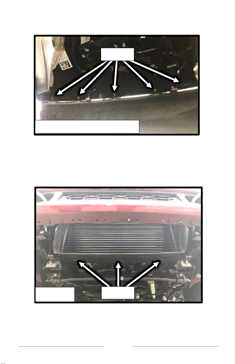
Step 2:
•Remove the 14 nuts attaching the lower air dam to the front
bumper. See Figure 2.1. The middle four nuts can be accessed
through the front opening in the air dam.
•Using a screwdriver, carefully disconnect the two push clips in the
bottom of the air dam.
•Using a screwdriver, carefully disconnect the two remaining clips
holding the air dam to the bumper.
•Set the air dam aside.
Page 5
Step 2 Cont.
Step 3:
•Remove the three plastic push clips on the bottom of the
intercooler shroud. See Figure 3.1
Figure 2.1 –Driver Side Shown
Remove
Figure 3.1
Remove
Page 6
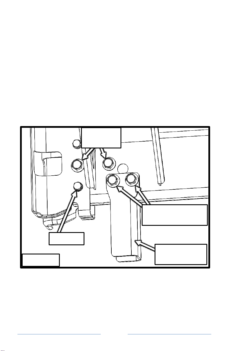
Step 3: Cont.
•Remove the four bolts (two per side) holding the intercooler
shroud to the front of the intercooler. See Figure 3.2
•Remove the charge air cooler shroud. Be careful not to damage
the charge air cooler fins.
Figure 3.2 –Passenger side shown
Remove
Frame

Page 7
Step 4:
•Using a reciprocating body saw, or other method, trim the center
of the intercooler shroud as shown in figure 4.1.
•Using a reciprocating body saw, or other method, trim the center
of the air dam as shown in figure 4.2.
3-1/4”
2-3/4”
Figure 4.1
Figure 4.2
cut even with top of openings
7-1/2”
2-5/8”
Page 8
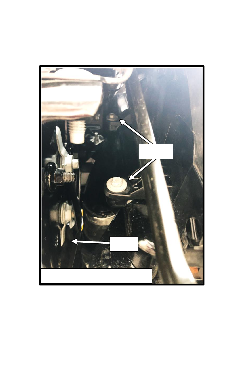
Step 5:
•Starting on the driver side, remove the M12 bolt just forward and
below of the front body mount. See Figure 5.1.
•Remove both M16 tow hook bolts if equipped. Take note of the
factory nut and tab orientations on the opposite side of the frame
before removal.
•Remove both M16 vertical frame bracket bolts and the vertical
frame bracket if equipped.
•If equipped, slide the tow hook out from the bumper and set it
aside.
•Repeat the removal process for the Passenger side of the vehicle.
Proceed to Step 6.
M16 Tow
Hook Bolts
M12 Bolt
Figure 5.1
M16 Vertical Frame
Bracket Bolts
Vertical Frame
Bracket
Page 9
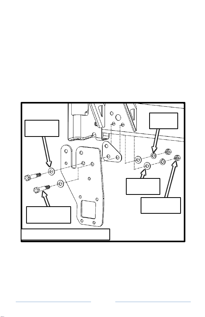
Step 6A: Vehicles equipped with vertical frame brackets.
(For vehicles not equipped with Vertical Frame Brackets, proceed
to Step 6B)
•Insert one 5/8”-11 x 4” Grade 8 hex bolt with one 5/8” SAE flat
washer into each of the two lower rear holes in a Side Plate.
•Place a side plate spacer over the threaded ends of the bolts, then
guide the bolts into the frame. See figure 6A.1.
•Secure each bolt with one 5/8” SAE flat washer, one 5/8” split
lock washer, and a 5/8”-11 grade 8 hex nut. Leave the hardware
as loose as possible. Repeat for the opposite side of the frame.
Proceed to Step 7.
Figure 6A.1 –Driver side shown
5/8” SAE
Flat Washer
5/8”-11 x 4”
Grade 8 Hex Bolt
5/8” SAE
Flat Washer
5/8” Lock
Washer
5/8”-11 Grade
8 Hex Nut
Page
10
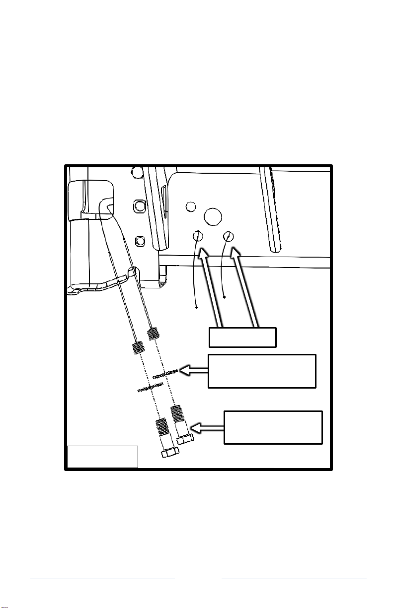
Step 6B: Vehicles not equipped with vertical frame brackets.
•Guide the coiled end of a 5/8” bolt fisher into each of the two
lower rear holes, and out the front end of the frame. See Figure
6B.1.
•Attach one 5/8” internal/external tooth lock washer, and one 5/8”-
11 x 2” grade 8 hex bolt to each bolt fisher.
•Pull on the straight end of each bolt fisher until the threads of both
bolts are protruding from the two lower rear holes. Keep the bolt
fishers attached.
Figure 6B.1
Lower Holes
5/8” internal/external
tooth lock washer
5/8”-11 x 2” grade 8
hex bolt
Page
11
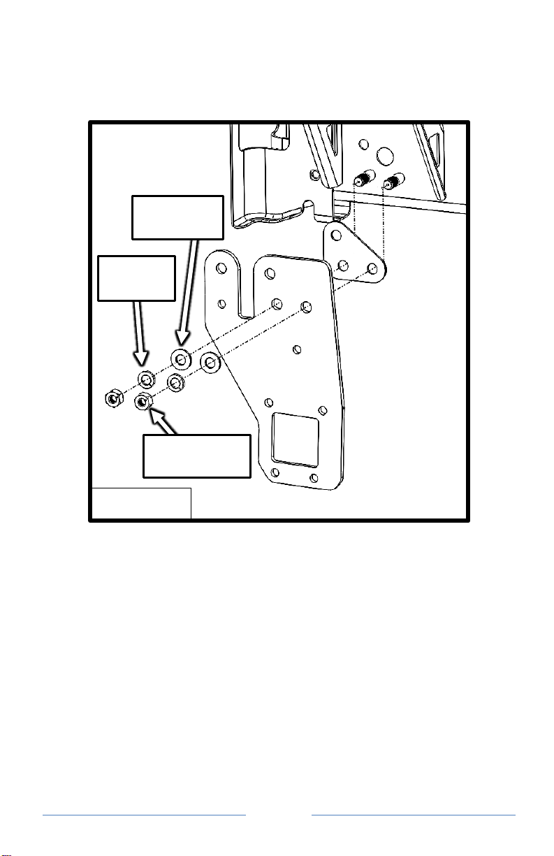
•String the bolt fishers through a side plate spacer, and then
through the lower rear mounting holes in a side plate. See Figure
6B.2
•Place the side plate spacer and side plate up against the frame.
•Carefully remove one of the bolt fishers, then secure the bolt with
one 5/8” SAE flat washer, one 5/8” split lock washer, and a 5/8”-
11 grade 8 hex nut. Keep the hardware as loose as possible.
Repeat for the other bolt.
•Repeat step 6B for the opposite side of the frame, then proceed to
Step 7.
Figure 6B.2
5/8” Lock
Washer
5/8” SAE
Flat Washer
5/8”-11 Grade
8 Hex Nut

Page
12
Step 7A: Vehicles equipped with tow hooks.
(For vehicles not equipped with tow hooks, proceed to Step 7B)
•Slide the tow hook back through the bumper and into the frame.
•Install one M16-2.00 x 100mm class 10.9 hex bolt with one 5/8”
SAE flat washer into each of the two upper holes in the side plate
and through the tow hook. Loosely thread each of the bolts into
the factory nuts.
•Install one M12-1.75 x 100mm class 10.9 hex bolt with one M12
flat washer into the remaining hole. Loosely secure the bolt with
the factory nut. See Figure 7A.1.
•Repeat Step 7A for the passenger side of the truck, then proceed
to Step 8
Figure 7A.1
M12-1.75 x
100mm class
10.9 hex bolt
M12 SAE
flat washer
M16 SAE
flat washer
M16-2.00
x 100mm
class 10.9
hex bolt

Page
13
Step 7B: Vehicles not equipped with tow hooks.
•Guide the coiled end of a 5/8” bolt fisher into each of the two
upper holes, and out the front end of the frame. See Figure 7B.1.
•Attach one 5/8” internal/external tooth lock washer, and one 5/8”-
11 x 2” grade 8 hex bolt to each bolt fisher.
•Pull on the straight end of each bolt fisher until the threads of both
bolts are protruding from the two upper holes. Keep the bolt
fishers attached.
Figure 7B.1
5/8”-11 x 2” grade 8
hex bolt
5/8”
internal/
external
tooth
lock
washer
Page
14
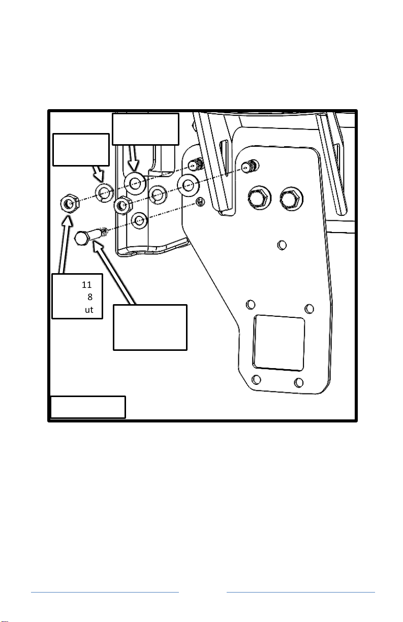
•Carefully remove one of the bolt fishers, then secure the bolt with
one 5/8” SAE flat washer, one 5/8” split lock washer, and a 5/8”-
11 grade 8 hex nut. See Figure 7B.2. Keep the hardware as loose
as possible. Repeat for the other bolt.
•Install one M12-1.75 x 100mm class 10.9 hex bolt with one M12
flat washer into the remaining hole. Loosely secure the bolt with
the factory nut.
•Repeat step 7B for the passenger side of the frame, then proceed
to Step 8.
Figure 7B.2
5/8” SAE
Flat Washer
5/8” Lock
Washer
5/8”-11
Grade 8
Hex Nut
M12-1.75 x
100mm class
10.9 hex bolt

Page
15
Step 8
•Reattach the intercooler shroud and air dam in the reverse
order of removal. Be careful! Do not allow the studs in the air
dam to scratch the paint.
•Install the cross tube into the side plates, one side at a time. It
is easiest to angle the cross tube into position with one side
farther towards the rear of the truck. You will need to flex the
air dam downwards until the hitch receiver aligns with the
cutout.
•Attach both side plates to the cross tube by installing one 1/2”-
13 x 1-1/2” grade 8 hex bolt with one 1/2” SAE flat washer
into each of the five holes per side plate. Secure each bolt with
one 1/2 split lock washer and one 1/2”-13 grade 8 hex nut.
See figure 8.1
Figure 8.1
1/2”-13 x 1-1/2”
grade 8 hex bolts
1/2”-13 grade
8 hex nuts
1/2” lock
washers
1/2” SAE
flat washers
Page
16
Step 9
Torque the hardware in the following order.
•Torque the M16 bolts to 200 ft-lbs (some installations will not
use any M16 bolts)
•Torque the 5/8” bolts to 200 ft-lbs
•Torque the M12 bolts to 80 ft-lbs
•Torque the 1/2” bolts to 80 ft-lbs
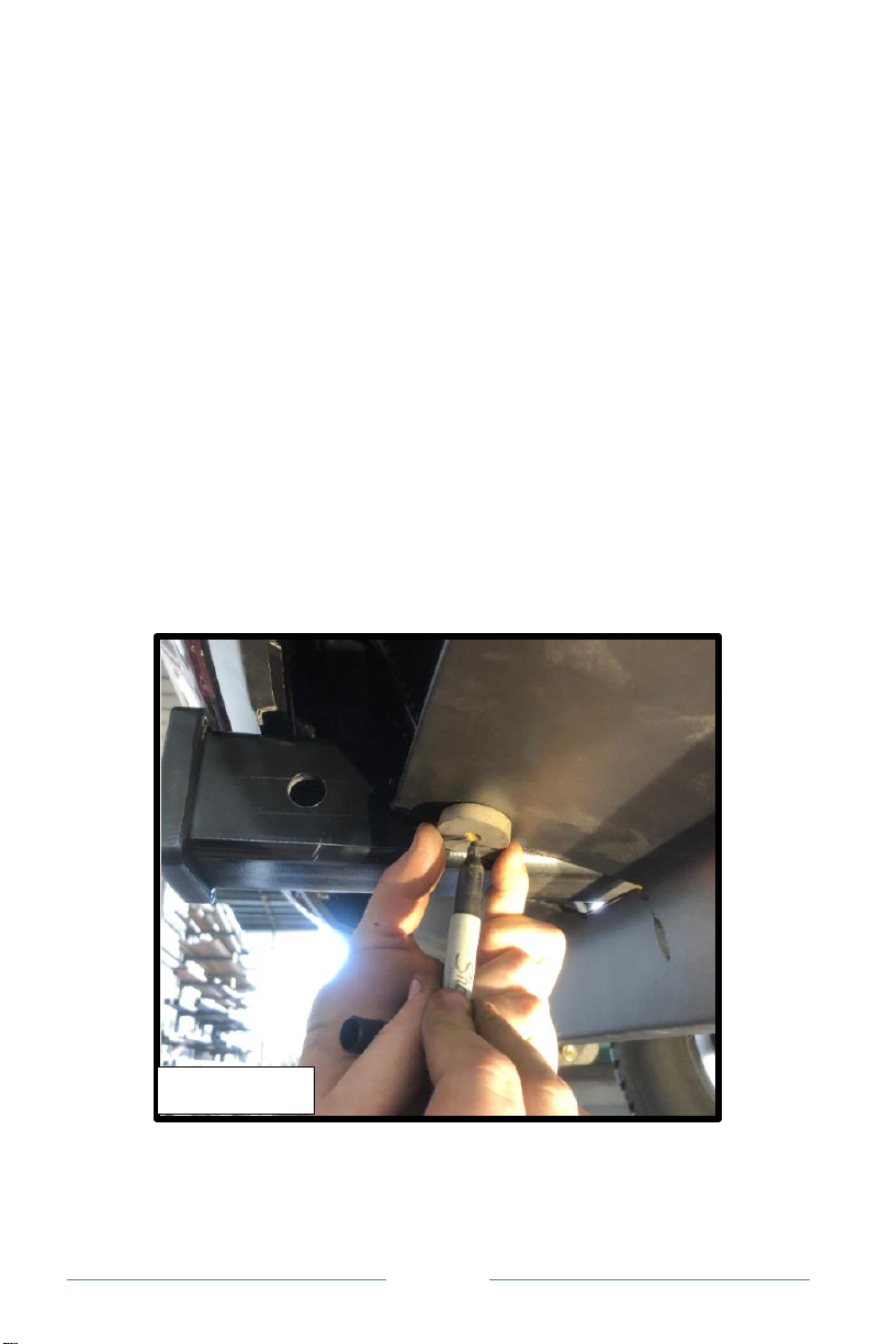
Step 10
•Hold the hole alignment plate up against the bottom of the air
dam and align it with one of the two tabs on the receiver. Use
a felt tipped pen to mark the hole location. Repeat for the
opposite side of the receiver. See Figure 10.1.
•Drill a 1/4” hole in the two marked locations.
Figure 10.1
Page
17
•Install one 1/4”-20 x 3/4” button head bolt up into each hole
the air dam and through the tab on the side of the receiver.
•Secure each bolt with one 1/4” SAE flat washer and one 1/4”-
20 thin nylock nut. Tighten until snug. Do not over tighten as
it may deform the plastic.
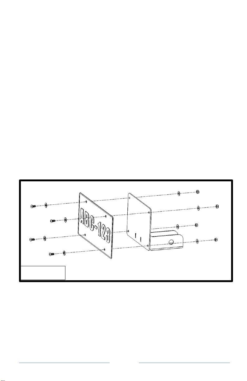
Step 10
•Install one 3/8” hole plug into the holes left in the bumper by
the original license plate bracket.
•Install one 1/4”-20 x 1/2” button head bolt with one 1/4” SAE
flat washer into each hole in the license plate and through the
license plate bracket. Secure each bolt with one 1/4” SAE flat
washer and one 1/4”-20 thin nylock nut. See Figure 10.1.
•Slide the license plate bracket into the hitch receiver and pin it
in place using the supplied 5/8” hitch pin and clip.
Installation is complete.
Figure 10.1

Page
18
WARRANTY/DISCLAIMER
INFORMATION
Torklift Central requires proof of purchase for warranty claim
registration, with pictures of any defective product before issuing a
replacement. Torklift will not accept claims on any product without
proof of purchase, which can be faxed, scanned, emailed or mailed to
the information provided below. Torklift Central warrants its hitches,
custom hitch receivers and accessories (excluding electrical wire
harnesses which carry a warranty from their specified manufacturer)
from date of purchase against defects in material and workmanship
under normal use and service for the ownership life of the original
consumer purchaser. Torklift Central will replace free of charge any
part that proves defective in material or workmanship when presented
to Torklift Central, transportation charges prepaid by purchaser, at the
address below.
This warranty is limited to defective parts
replacement only. Labor charges and/or damage
incurred in installation or replacement, as well as
incidental and consequential damages connected
therewith are excluded.
This warranty does not include normal wear and tear or the
finish and paint. Rusting, cracking or peeling of the finish is also
excluded. Some states do not allow the exclusion or limitation of
incidental or consequential damages, so the above limitation or
exclusion may not apply to you. Any damage to Torklift Central
products as a result of misuse, abuse, neglect, accident, improper
installation or any use violative of instructions furnished by Torklift
Central will void the warranty. This warranty gives you specific legal
rights and you may also have rights, which vary from state to state.
With warranty service, you may be able to go to a small claims court,
a state court or a federal district court.

Page
19
Although Torklift Central trailer hitches are both tested and rated for
towing within the specific capacity label found on each trailer hitch.
Torklift Central assumes no liability for vehicle manufacturers
warranty due to the use of a Torklift Central trailer hitch being used
for towing behind any vehicle or using the trailer hitch in a manner
that it was not designed for. Although this specific trailer hitch has a
load rating, which includes trailer tongue weight, and a trailer weight
carrying capacity, Torklift Central is not responsible for the voiding
of any warranty on any vehicle due to factory towing limitations. All
vehicle warranties are the sole property and responsibility of the
owner of the vehicle that the Torklift Central trailer hitch is installed
upon. Torklift Central does not endorse towing behind any vehicle if
the vehicles manufacturer states that towing is not recommended.
Check your vehicle’s owner’s manual for the proper tow rating of
your vehicle.
ADDRESS: 315 Central Ave N. Kent, WA 98032
*WARNING* Your vehicle may have a lower tow rating than this
trailer hitch. If your vehicle’s tow rating is less than the rated towing
capacity on your Torklift Central trailer hitch, your trailer hitch
capacity is limited to your vehicle’s factory rated towing capacity.
*DANGER* Never exceed your vehicle's manufacturer's
recommended towing capacity which may be a lower rating than this
trailer hitch
Table of contents
Other Torklift central Automobile Accessories manuals

Popular Automobile Accessories manuals by other brands

EUFAB
EUFAB JAMO manual

Prorack
Prorack K384 Fitting Instructions for Basic Carrier

NORTHMAN
NORTHMAN 2500 Series Installation & operating guide

Steinhof
Steinhof P-045 FITTING AND OPERATION MANUAL

Firstech
Firstech BLADE Series install guide

Metra Electronics
Metra Electronics CHTO-013 installation instructions


