Tormax Automatic Smart Drive 1101 User manual

Installation On Site
for Automatic Swing Doors SWINGDOOR
Smart Drive 1101
T-1132 e 3.03


Installation On Site SWINGDOOR Smart Drive 1101 T-1132 e 3
First edition: 9.02 provisional for 0-Series
Update: 3.03
We print on environment-friendly paper bleached without chlorine.
The enterprises Landert Motoren AG and Landert GmbH are certified according to ISO 9001.
Contents
1 Introduction 4
2 Safety 5
2.1 General Safety and Accident Prevention
Regulations 5
2.2 Safeguarding Danger Points 6
2.3 Organizational Measures 7
3Basic Functions 8
4 Installation 10
4.1 Lintel Mounting Standard Linkage 11
4.2 Door Leaf Mounting Standard Linkage 12
4.3 Sliding Lever u 13
4.4 Panic Fitting u 14
5Mechanical Adjustments 15
6Electrical Connections 16
7Commissioning of the Automatic System 19
7.1 Commissioning with “Teach-In General” 19
7.2 Programming Procedure 19
7.3 Programming Examples 20
7.4.1 Programmable Functions 22
7.4.2 Effect of Homing in Speed and Angle for Homing in Speed Closing 23
7.5 Low Energy Applications 24
8Trouble Shooting 25
9Check List 26
Fold-out page

4Installation On Site SWINGDOOR Smart Drive 1101 T-1132 e
Addressee/Status
Area of Application
1Introduction
These instructions are addressed at qualified installation personnel and contain all
required information for the installation on site.
This document is applicable to automatic TORMAX doors of type SWINGDOOR Smart
Drive 1101.
Non-compliance endangers the safety of the installation personnel, the system operator
or the user.
Warning of electrical voltage.
Passages with text on grey background must be absolutely observed for reliable
performance of the system! Neglect can cause material damages.
This symbol marks optional components, which are not installed in all units.
These instructions are available in different languages. Please ask your TORMAX
dealer.
For installation and commissioning of this system, the following instructions and data
sheets are useful; get hold of these documents before beginning the assembly work!
•Operating instructions T-1134 e
•Wiring diagram lintel mounting T-1135 e
• Wiring diagram door leaf mounting T-1154 e
•Drilling template T-1138
•Dimensional drawings standard linkage lintel mounting T3-386-40
•Dimensional drawings standard linkage door leaf mounting T3-386-41
•Dimensional drawings sliding lever lintel mounting T3-386-42
•System test book International: T-895 e
Explanation of Symbols
◆
!
SWINGDOOR
Smart Drive 1101
Languages

Installation On Site SWINGDOOR Smart Drive 1101 T-1132 e 5
2Safety
2.1 General Safety and Accident Prevention
Regulations
Prior to installation or commissioning, read and follow this information that is being
described on this page—especially the following notes relating to safety—and adhere to
them at all times! Damage to the unit and personal injury may result if these instructions
were not carefully followed.
Pay particular attention to the specially marked notes in this manual (for an explanation
of the symbols please refer to chapter 1)!
TheseproductsareUnderwritersLaboratories,Inc.(UL)listedandcULcertifiedfor
the Canadian marketplace, and therefore comply with the requirements of the
National Electrical Code (NEC) and the Canadian Electrical Code (CEC). Installa-
tionsintendedtomeetULandcULrequirementsmustbefollowedasdescribedin
the instruction provided herein. These are minimum standard requirements.
Where local codes exceed these requirements, they must be followed as well.
Preventing General Hazards and Possible Damage to This Equipment
• Keep fingers away from all moving parts.
•Verify that the power selection switch is set to the correct voltage before start-up.
•The power supply cable (flexible cord) should be entered at the end side that is close
to the input power supply plug. It should not be routed through doorways, window
openings, walls, ceilings, floors, etc. The power supply cable (flexible cord) should not
be attached or otherwise secured to the building structure. It should not also be
concealed behind walls, etc.
•Never allow the power supply cable (flexible cord) to become entrapped in moving
parts of the operator, door, or system.
•The power receptacle must be of the grounding-type. It is very important that the unit
will be properly grounded.
•To reduce the risk of electrical shock, this equipment has a grounding-type plug that
has a third grounding pin. This plug will only fit into a grounding-type outlet. If the plug
does not fit into the outlet, contact a qualified electrician to install the proper outlet. Do
not change the plug in any way.
Warnings of Dangerous Electrical Voltages or Current
•Be sure the electrical power is disconnected and locked-out when working on the
operator unit.
•Install the electrical cables and power only after the mechanical installation to the unit
is done.
•Turn on the power to the operator unit only after all internal cables are connected. Do
not connect cables while the unit is powered.
•Always use appropriate tools for installation and repair.
Prior to commissioning or performing any work on the door system, the operating
instructions for the TORMAX operator and the following safety directions should be
studied with great care and must be observed!
In any case, please pay attention to the specially marked notes within this document (see
chapter 1 for an explanation of symbols).
General safety Instructions
!

6Installation On Site SWINGDOOR Smart Drive 1101 T-1132 e
The TORMAX operator is designed according to the current state of technology as well
as the recognized safety-relevant regulations and is intended exclusively for the
deployment in conjunction with automatic interior and exterior doors (without wind loads)
used by people e.g. in hospitals, homes for the elderly, shopping centres, office buildings
and large-scale enterprises. The operator corresponds to protective class IP 22. Without
additional safety precautions, it may only be installed within, i.e. at the inside, of buildings.
Any other use or any use exceeding this aim is determined to be not for its intended
purpose and may lead to personal injury to the user or a third party. Furthermore, the
system or other material assets can be damaged. The manufacturer will not be
responsible for any damage resulting from this; the risk is carried entirely by the operator
of the door system.
The operating, service and maintenance conditions specified by the manufacturer are to
be maintained. The persons entrusted with the service and maintenance must be
acquainted with the matter and informed about any possible danger.
To ensure a reliable function of the door the moment of friction may not exceed 10 Nm.
In addition to the operating instructions, the legal and other obligatory regulations for
accident prevention and environmental protection, in the respective country where the
door system is operated, shall be applicable. The special directives for automatic doors
(e.g. of the European committee for standardization CEN) must be adhered to. Further-
more, the operational/national regulations apply.
Arbitrary changes to the system will exempt the manufacturer from any liability for
damages resulting from this.
2.2 Safeguarding Danger Points
General
Automatic door systems are to constructed in such a manner that on opening and closing
motions endangerments through jamming, shearing and drawing-in are avoided or
safeguarded against, for example through:
–Safety separations
– Limitation of the door-leaf forces
–Monitored safety facilities
–Separating protective facilities
Sufficiently dimensioned minimum safety distances to prevent crushing are:
–for fingers or hand 25 mm
–for the head 200 mm
–for the body 500 mm
Fingers are unlikely to penetrategaps ≤8 mm in powered pedestrian door installations.
The safety measures may be used in combination.
Use for Intended Purpose
!
prEN 12650-2:2002
Maximum Door Leaf Weights
0
50
100
150
200
250
300
350
400
450
0.6 0.8 1 1.2 1.4 1.6
Leaf width
Door leaf weight
kg
m
T1132/40e

Installation On Site SWINGDOOR Smart Drive 1101 T-1132 e 7
Automatic Swing Doors
Door leaves may not open directly into areas in which other transit traffic takes place. If
door leaves open into an area in which there might be people, safety precaution are to
be taken if this is judged as necessary by the risk evaluation.
Danger points in the range of the opening motion are considered as safeguarded if:
–There is an adequate safety separation regarding the endangered parts of the human
body between the secondary closing edge and adjacent parts of the environment,
or
–The forces of the door leaves are limited to safe values,
or
–Monitored protective facilities will be installed between the secondary closing edge and
adjacent parts of the environment,
or
–The area of the secondary closing edge is protected with separating protective
facilities.
Danger positions during the closing motion are secured – depending on application – if
–The motion travel of a door leaf is continuously supervised through (error-proof and
monitored) presence sensors,
or
–Monitored protective facilities are installed at the main and/or secondary closing edge,
or
–The motion travel of a door leaf is secured with switching mats.
The leaves must be manufactured from materials that will not lead to a potential danger
of injury when breaking (e.g. toughened safety glass, compound safety glass etc. when
using glass).
2.3 Organizational Measures
The installation on site may be carried out only by qualified personnel who have sufficient
knowledge in the area of the power-operated doors due to vocational training and
experience and are acquainted with the relevant national workers protection rules,
accident prevention regulations, directives and generally recognized rules of the
technology to such an extent that they can judge the safe-for-working status of power-
operated doors.
Experience/vocational training in metal construction and in fastening techniques is a
requirement.
If necessary, qualified employees of the contract partner can make use of the training
offered by TORMAX (training courses).
Depending upon leaf weight, an assistant must be available for the installation.
•Use the system only in a technically sound state. Eliminate faults immediately that may
impair safety.
•Keep fingers away from any mobile parts. Special caution is required in the area of the
drive lever, the linkage and the secondary closing edges of the hinges.
•Use exclusively tools that are suitable for the respective work procedure. Pay attention
to good condition of the tools.
•Electric voltage/current: The operator is to be disconnected from electrical mains
before any work is performed on electrical parts.
Install cabling only after the installation is complete.
Plug in the power plug only after all internal cables are connected.
!
Requirements for Installa-
tion Personnel
Fundamental Safety Meas-
ures – Appropriate Behav-
iour

8Installation On Site SWINGDOOR Smart Drive 1101 T-1132 e
3Basic Functions
Motion Control – General
The door opens motor-driven in accordance with the adjusted speed against the installed
spring. Ahead of the open position, the motor torque is reduced and the door is braked
down by the spring. The door is held in the open position by a reduced motor torque. The
closing action is performed through spring force only. Thereby, the motor adjusts the
speed. At the completion of the closing motion, deceleration occurs with adjustable
homing in speed over an adjustable angle (see section 7.4.2). The motor is switched off
when the door is closed.
Functionality of the unit
Opens the door in operating mode AUTO and in operating mode OFF in accordance
with “Teach-In General”.
Opens the door in operating mode AUTOin accordance with “Teach-InGeneral”, or with
“Teach-In Key Switch” if this was performed after “Teach-In General”.
This prevents the door from opening. It stops the door during opening.
If both, the safety device in opening direction and the safety device in closing
direction, respond at the same time during a motion, the door stops in place. Through
“Teach-In General”, the safety sensor is disabled automatically over a predetermined
door swing range. If this function is not used, a jumper is inserted between 14–15.
Standard function:
Safety device in closing direction (safety sensor riding along in closing direction).
The door remains open. A commenced closing motion is reversed.
If both, the safety device in opening direction and the safety device in closing
direction, respond at the same time during a motion, the door stops in place.
Optional functions:
Safety device for the swing area
The door remains open or closed. A commenced motion is completed.
The safetydeviceinopeningdirectionhas a higher priority than the safetydevicefor
the swing area.
Safety Device Bodyguard
This function is only in use with the safety device “Bodyguard” of BEA.
The door remains open or closed. A commenced motion is completed. The safety
deviceinopeningdirectionhas a higher priority than the safetydevice“Bodyguard”.
Using this function automatically changes the settings of FeedbackDoorStateto “door
opening or door open”.This feature is compulsory for the function “Bodyguard”
(See Feedback Door State)
If these safety functions are not used, a jumper is inserted between 18–19.
Output for active testing of the safety device in opening direction and safety device
in closing direction (e.g. for Eye-Tech of BEA).
An opening can only be initiated through the key switch.
An opening can be initiated by an activator, a key switch and also by “Push and Go”
depending upon configuration.
Activator
Key Switch
Safety device in closing
direction/safety device for
the swing area/
Safety Device Bodyguard
Safety device in opening
direction
Test of safety devices
Operating Mode OFF
Operating Mode AUTO

Installation On Site SWINGDOOR Smart Drive 1101 T-1132 e 9
Feedback Door State
The door opens and stops in open position. It opens according to the settings of “Teach-
In General”.
Unlocks on each opening command. On completion of the openingtimedelay, the door
starts opening. When the door has moved somewhat in opening direction, the door lock
drops off again. The door lock is activated only in proximity of the “door closed” position.
The feedback “door closed” (or “door open” if reconfigured) between 11–12 is only valid
as long as mains supply is available. This message is established as soon as the
processor considers the driving function as complete. Connection for 24 VDC relay or
signal light. Transistor output short circuit proof in relation to internal supply voltage
24 VDC / 0.75 A.
If a second opening width has been configured (Teach-In SS) the feedback “door open”
is as follows:
Triggering of opening Feedback defined by
Activator Teach-In General
Key-switch Teach-In key-switch
Push-and-Go Teach-In General
Manual operation the smaller of both opening widths
Using this function automatically changes the settings of FeedbackDoorStateto “door
opening or door open”.The other feed back types can be chosen, but have no effect
whatsoever. (See: Safety device Bodyguard).
The control system Smart Drive 1101 provides a power supply of 24 VDC for sensors,
doorlockand signalling. The power supply may be continuously loaded with maximally
0.75 A. With loads >0.75 A, the point LED on the display goes out. On overload, the unit
switches itself off automatically. In this condition, manual operation of the door is possible
with controlled spring closing action.
If the door hits a firm obstacle during opening, the motor driven opening procedure is
terminated immediately. If the door hits a firm obstacle during closing, the weak spring
closing force remains in existence. The next opening command opens the door again as
usual.
The door opens when an impulse is received, remains in the valid open position during
the valid hold-open time, and closes thereafter again.
The door opens when an impulse is received (from the key switch or an activator) and
remains in the open position. The door closes immediately after the next impulse. The
motional sequence depends on the settings of the respective “Teach-In”.
The motor is switched off immediately when the door is blocked.
Motor and transformer contain thermal relays that interrupt the current supply to the
control system at 110 °C. The system operates as during a power failure until the
temperature drops to 85 °C.
The door can be manually opened if the doorlockcan be unlocked with the door handle.
The door closes through spring force. The motor, which is controlled short-circuited,
controls the closing action with constant braking power. After return of power, the system
is immediately ready for use again.
Power Supply 24 VDC
Reversing Motion
Time Control
Step Control
Internal Protective Device
Power Failure
Door Lock
Operating Mode OPEN

10 Installation On Site SWINGDOOR Smart Drive 1101 T-1132 e
4Installation
T1132/9
T1132/10
T1132/11
T1132/13
T1132/16
T1132/14
T1132/15
T1132/17
T1132/18
T1132/19
T1132/20
T1132/21
see 4.1
see 4.2
see 4.3
see 4.4
Overview of mounting methods
T1132/24
T1132/22
T1132/45

Installation On Site SWINGDOOR Smart Drive 1101 T-1132 e 11
4.1 Lintel Mounting Standard Linkage
T1132/10
T1132/28
L
A
B
45
C
E
F
D
310
540
50
I
90°
M
H
G
80
K
M
T1132/25
8
23
80 310
290
540
20
50
2x Ø7
4x Ø7
30
580
290
20
Z
Y
45
20
X70.5
116
85
YZ
0 – 10 33
X
–40…+107 +105…+252
0 – 70 93 –40…+107 +105…+252
A) Glue on template
B) Drill holes
C) Attach cone, length according Y, surfaces parallel to side
plates
D) Tighten hexagon-socket screw
E) Fasten operator
F) Fasten bearing trestle according to dimensional specifi-
cations on door leaf
G) Attach connecting part at right-angle to the operator to
cone (length in accordance with Y)
H) Interconnect bearing trestle and adjustment member
I) Adjust adjustment member at right-angle to the lintel and
tighten screws
K) Interconnect connecting part and adjustment member
L) Fasten covers
M) Snap in side plates

12 Installation On Site SWINGDOOR Smart Drive 1101 T-1132 e
T1132/10
4.2 Door Leaf Mounting Standard Linkage
310
540
B
C
D
E
G
M
L
T1132/29
45
A
50
I
80
K
F
H
M
T1132/26
540
20
50
2x Ø7
4x Ø7
30
8
23 580
290
Z
Y
45
20
X70.5
116
85
20
80 310
290
YZ
0 – 10 33
X
–40…+107 +105…+252
0 – 70 93 –40…+107 +105…+252
A) Glue on template
B) Drill holes
C) Attach cone, length according Y, surfaces parallel to side
plates
D) Tighten hexagon-socket screw
E) Fasten operator
F) Fasten bearing trestle according to dimensional specifi-
cations on lintel
G) Attach connecting part at right-angle to the operator to
cone (length in accordance with Y)
H) Interconnect bearing trestle and adjustment member
I) Adjust adjustment member at right-angle to the lintel and
tighten screws
K) Interconnect connecting part and adjustment member
L) Fasten covers
M) Snap in side plates

Installation On Site SWINGDOOR Smart Drive 1101 T-1132 e 13
4.3 Sliding Lever ◆
T1132/11
A) Glue on template
B) Drill holes
C) Attach cone (length according Y)
D) Tighten hexagon-socket screw in a way that the
cone can be turned by hand
E) Fasten operator
F) Fasten sliding rail according to dimensional
specifications on door leaf
G) Insert cover profile
H) insert bearing trestle into sliding rail
I) Mount side covers of sliding rail
Connect to mains,
Trigger factory reset, (see paragraph 7.3 programmimg table)
Choose operating mode OPEN (with operating mode switch ◆or by connecting terminals no 2 and 3)
axis will turn 20°
K) Slide connecting part over cone and push up to the operator
insert other end completely into bearing threstle, tighten cone Konus (hexagon-socket screw) and connecting part
L) Fasten covers
M) Snap in side plates
C
D
E
GK
A
B
450
250
45
F
H
I
I
T1132/38
M
M
T1132/39
UW
0 – 20 59 ±3
X
0…+150
0 – 80 119 ±3 0…+150
540
20
4x Ø5
4x Ø7
30
160 + x/2
290
20
23
32
250
40
140
140
350
X
20
70.5
116
W
U
3±3
85
580
8
140
45
49
500

14 Installation On Site SWINGDOOR Smart Drive 1101 T-1132 e
4.4 Panic Fitting ◆
T1132/11
C
D
G
K
A
B
540
250
45
F
H
I
T1132/23
E
400
100 ... 300
L
N
M
M
UW
0 – 20 59 ±3
X
0…+150
0 – 80 119 ±3 0…+150
X
20
70.5
116
W
U
3±3
85
45
49
540
20
4x Ø5
4x Ø7
30
290
20
23
32
250
580
8
4x Ø5
34
19
160 + X/2
350
130
130 130 110
700
T1132/44
A) Glue on template
B) Drill holes
C) Attach cone (length according Y)
D) Tighten hexagon-socket screw in a way that the
cone can be turned by hand
E) Fasten operator
F) Fasten hinge of panic fitting and holding plate
according to dimensional specifications on door
leaf
G) Adjust the desired holding force of the magnet by
sliding it in the rail.
H) insert bearing trestle into sliding rail
I) Mount side covers of sliding rail
Connect to mains,
Trigger factory reset, (see paragraph 7.3 programmimg table)
Choose operating mode OPEN (only with operating mode switch ◆or by connecting terminals no 2 and 3)
axis will turn 20°
K) Slide connecting part over cone and push up to the operator
insert other end completely into bearing threstle, tighten cone (hexagon-socket screw) and connecting part
L) Fasten cover
M) Snap in side plates
N) Fasten rubber stop on the lintel, so that the connecting part will rest on it, when triggering the panic fitting.

Installation On Site SWINGDOOR Smart Drive 1101 T-1132 e 15
5Mechanical Adjustments
The internal OPEN end-stop is only to be used as a safety device (e.g. wind load, manual
operation). In automatic operation it must not be hit!
•Open the door to the greatest possible opening width and secure it.
• Adjust the OPEN end-stop.
The door should only be opened so far that the standard linkage cannot tip over and the
sliding lever does not leave the rail.
Door in open position at the end stop (internal
OPEN end-stop or door stopper).
T1132/30
!
!
max. 170 °
T1132/35

16 Installation On Site SWINGDOOR Smart Drive 1101 T-1132 e
6Electrical Connections
Observe wiring diagram T-1135 e for lintel mounting and T-1154 e for door-leaf mounting!
A system switch must be mounted on site.
Before beginning the work described here check that the mains supply is switched off.
If possible, route the mains connection along the side of the power supply to the operator.
The connecting cables must be of the type “PVC cable H05VV-F” or “rubber hose cable
H05RR-F”.
Round the edges and remove burrs from all conduits used for the mains connection.
•Remove mains supply cover (1).
•Connect the mains cable to terminal (11) in
accordance with figure.
•Route the mains cable either through the
prepared holes of the side cover or through
the slots in the mounting plate.
•Use only cable bushings made from syn-
thetic materials. Metallic bushings are to be
earthed.
•Check correct adjustment of the voltage
selector (12) and reinstall the mains supply
cover (1).
•Secure mains cable with a cable strap at the
plastic nub (17) and at the supporting metal
sheet.
•Mount the emergency-off switch in accordance with the contract order and route the
mains connection via emergency-off switch.
•Mount in accordance with contract order
•Connect in accordance with connection diagram and the manufacturer’s specification
•Adjust the detection field/sensitivity and action radius according to the requirements
and the surroundings of the system.
10AT
L1 3mm
N
230/115V~
50/60 Hz
T1132/1
!
Mains Connection
Emergency-off Switch ◆
T1132/34
L1
N
12
11
1
Activator and Safety
Facilities ◆

Installation On Site SWINGDOOR Smart Drive 1101 T-1132 e 17
Terminal Connections
Legend:
*programmable
+24 V 24 VDC (21 … 24 VDC)
IN Input 24 VDC / 3 mA
OUT Output NPN integrated protective diode
T1132/3e
1 2 3 4 5 6 7 8 9 10 11 12
IN
GND
IN
GND
IN
+24 V
GND
IN
OUT
+24 V
OUT
+24 V
Activator
Status indication
door closed/*open
OFF
AUTO
OPEN
Key switch
Door lock 24 VDC
locked currentless
* unlocked currentless
–
+
No protective
circuit necessary
T1132/6e
Safety devices without
monitoring
13 14 15 16 17 18 19 20
–
+
GND
IN
OUT
24 V
GND
IN
OUT
24 V
+
+
–
+
Safety device
in opening direction
Safety device in
closing direction /
*Swing area
Safety devices with
monitoring
Safety device
in opening direction
13 14 15 16 17 18 19 20
Safety device in
closing direction
BEA
Eye-
tech
–
+
BEA
Eye-
tech
–
+
1
7
6
5
2
8
7
6
5
2
8
GND
IN
OUT
24 V
GND
IN
OUT
24 V
+
+
1

18 Installation On Site SWINGDOOR Smart Drive 1101 T-1132 e
Safety Device
BEA Bodyguard
T1032/7
8
!
Do not connect safety devices with monitoring and without monitoring in combination.
Overall, the 24 V power supply may be loaded with max. 0.75 A, on overload the point
LED goes out.
GND
+24 V
OUT
IN
GND
+24 V
OUT
IN
T1132/41
BEA
LO-21 BEA
Bodyguard
6orange
4weiss
8rot-weiss
9braun
6
7
5
3
1
13 14 15 16 17 18 19 20
2
Sicherheit
öffnen
910 11 12
+24 V
OUT
21
schwarz
rot

Installation On Site SWINGDOOR Smart Drive 1101 T-1132 e 19
7Commissioning of the
Automatic System
•The sensors, safety facilities and operating devices are professionally installed,
connected and preset.
•The operator is mounted professionally and the linkage is attached.
•The linkage and the internal end stop are adjusted and coordinated.
•The mains cable is expertly laid and connected.
•The system is switched on and is in operating mode AUTO.
•The point LED at the digital display is illuminated.
7.1 Commissioning with “Teach-In General”
During commissioning and in particular during “Teach-In” no people or items may be
present in the swing area of the door!
1. Push simultuaneosly the yellow and the blue key ➞ programming mode is active. (No
number is visible on the digital display yet).
2. Press yellow key once ➞display 0 is illuminated for max. 5 s.
(function “Teach-In” is now selected)
3. Press blue key once ➞display 0 flashes
(“Teach-In General”is now ready for execution)
4. Open the door by hand with the desired speed, keep it open as long as desired and
close it with the desired speed (the speeds are limited upward by the motor and the
spring force).
5. Open the door by way of the activator ➞the operator now opens the door and
reproduces the manually performed operational sequence for opening and displays
the sequence with the numbers 1 to 3 on the digital display.
During this sample opening sequence, the safety device in opening direction is
disabled automatically starting from the door position from where it responds. The
detection of the wall is thereby ignored for all following door openings.
“Teach In” is finished on completion of this test run. The learned values are now
stored. The function is departed automatically.
6. Check the safety facilities in opening and closing direction to find out whether they
react to a test object in the given swing area (see operating instructions T-1134
section 4.2).
Attention: Changing the position of the linkage requires a new Teach-In.
7.2 Programming Procedure
(See table in section 7.4)
Smart Drive 1101 possesses many useful features and parameters. These can be
programmed through 2 keys and a digital display as follows:
•Push simultuaneosly the yellow and the blue key ➞programming mode is active. (No
number is visible on the digital display yet).
•Select the desired function (1st number) with the yellow key.
•Press the blue key for confirmation of your choice.
➞2nd number (parameter) flashes.
•Modify the parameter with the yellow key as desired.
•For storage of the adjusted parameter, press the blue key again.
The procedure is thus complete and the 1st number (function) is displayed again.
Prerequisite
!
T1032/7
8

20 Installation On Site SWINGDOOR Smart Drive 1101 T-1132 e
If no action takes place for 5 s during programming, the procedure is aborted without
effect. (Return to functions or leaving programming mode). Exceptions are the Teach-
In functions (0), which can be cancelled by prssing the blue key, as long as the door
has not been moved.
The input and outputs are inactive as long as the control system is in the programming
mode.
7.3 Programming Examples
Program the desired functions now in sequence in accordance with the programming
table. The individual functions are described in section 7.4.
Check the programming options immediately after they are set!
Changing the opening time delay to 1.2 s.
•Read values from the programming table.
•Push simultuaneosly the yellow and the blue key ➞programming mode is active. (No
number is visible on the digital display yet).
•Press the yellow key several times until the number 3 appears on the display
➞Number 3 is lit (function)
•Press the blue key once for confirmation of the choice
➞Number 0, or the value programmed last, flashes (parameter)
•Press the yellow key several times until the number 3 appears
➞Number 3 flashes (parameter)
•Press the blue key once for storage of the adjusted value
➞Number 3 is lit (function)
Examination of the last programmed value of the release angle for the function
“Push and Go”.
•Push simultuaneosly the yellow and the blue key ➞programming mode is active. (No
number is visible on the digital display yet).
•Press the yellow key several times until the number 1 appears on the display
➞Number 1 is lit (function)
•Press the blue key once for confirmation of the choice
➞The last programmed value is now displayed and is flashing
The value associated with the displayed number can be inferred from the programming
table.
•Wait 5 s
➞The LED shows no 1 lit
•Wait 5 s
➞The point LED is lit
(programming was aborted automatically without any changes)
Factory reset
•Push simultuaneosly the yellow and the blue key ➞programming mode is active. (No
number is visible on the digital display yet).
•Press the yellow key several times until the number 9 appears on the display
➞Number 9 is lit (function)
•Press the blue key once for confirmation of the choice
➞Number 0 flashes (parameter)
•Press the yellow key once
➞Number 1 flashes (parameter)
• Press the blue key once to execute the factory reset
➞The point LED is lit
Example 2
Example 3
Example 1
Table of contents
Other Tormax Automatic Door Opening System manuals
Tormax Automatic
Tormax Automatic TORMAX 2201 User manual
Tormax Automatic
Tormax Automatic 2101 User manual
Tormax Automatic
Tormax Automatic iMotion 2202 User manual
Tormax Automatic
Tormax Automatic iMotion 1302.KI User manual
Tormax Automatic
Tormax Automatic Win Drive 2201 User manual

Tormax Automatic
Tormax Automatic T-1165 Operating instructions
Popular Door Opening System manuals by other brands
Label
Label NEXT 120s installation manual
Entrematic
Entrematic Ditec SPRINTSET installation manual

Label
Label NEXT 75 user manual
Entrematic
Entrematic Ditec VALLOKB installation manual
Entrematic
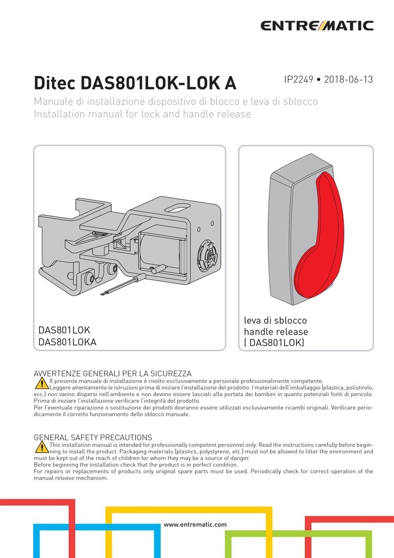
Entrematic Ditec DAS801LOK installation manual

Keyautomation
Keyautomation TURBO Instructions and warnings for installation and use
