Erreka Premis PREMIS200 Operating instructions

13
PREMIS200
Quick installation and programming guide English
IMPORTANT
NOTE
This quick guide is a summary of the complete installation guide. The full guide contains safety
warnings and other explanations that must be taken into account. The most recent version of
this guide and the installation manual are available at the “Downloads” section on Erreka’s
website: http://www.erreka.com.
The options and functions described in this guide apply for the firmware version indicated on
the circuit. The firmware, as part of a process of continuous improvement, is subject to new
functions or upgrades being included as a result of new versions not compatible with previous
ones. For this reason, some options or functions may differ or be unavailable if your firmware
is older than shown in this guide.
Elements of the complete installation
15 Door
16 Operator
17 Arm: Pull / Push
18 Side switch
19 Activation sensor
20 Safety sensor
21 Selector
22 Emergency Stop
23 Electrical lock
24 Smoke sensor (Fire door)
25 “Hold-open” retention magnets
(Fire resistant door)
26 Door stopper
27 External key
28 Fingers guards
ELECTRICAL CABLES:
Element Nº wires x section Remarks
Main power supply 3 x 1,5mm2
Selector 4 x 0,5mm2Screened cable
Safety sensor 6 x 0,5mm2Screened cable
Radar 4 x 0,5mm2
CAN (Double swing doors) 2 x 0,5mm2Screened cable
Stop 2 x 0,5mm2
Emergency 2 x 0,5mm2
Electrical lock (intercom) 2 x 0,5mm2With test; two more wires
Electrical lock (magnetic) 2 x 0,5mm2With test; two more wires
Hold-open retention magnets 2 x 0,5mm2
MSY-010/00 – 2022/10/11 firmware SW1.1.4. or later

14
Technical characteristics of the operator PREMIS200
CHARACTERISTIC PREMIS200 PREMIS200M
Dimensions Operator 644x75x138 mm
Power supply (V/Hz) 230VAC - 50/60 Hz 125VAC 50/60Hz
Power consumed (VA) 85VA
Motor voltage (Vdc) 40V
Max. torque (Nm) 50
Opening angle Adjustable from 0 -100º (with mechanical stopper)
Network input fuse 4 A (5X20)
Peripherals power supply (voltage) 24 Volts
Peripherals power supply (current) 1.5 Amps
Service temperature (ºC) -20ºC - 50ºC
Protection rating (IP) IP52
450
400
350
300
250
200
150
100
50
0
650 700 750 800 850 900 950 1000 1050 1100 1150 1200 1250 1300 1350 1400
10 seg
6 seg
4 seg
Door width (mm)
Weight (kg)
Type of arm
PULL SLIDE ARM - APR01
ARTICULATED PUSH ARM - APR02
SPECIAL PULL SLIDE ARM - APR09
Extension pivot (APR03 / APR04)
Coupling Measurement
Standard D = X mm
Standard + APR03 D = X + 25mm
Standard + APR04 D = X + 50mm
Standard + APR03 + APR04 D = X + 75mm
D
STANDARD + APR03
STANDARD + APR04
STANDARD + APR03 + APR04

15
OPENING
DIRECTION
OPENING
DIRECTION
0:150mm
600
25
X= 75
205
644
43
107
25
X=
107
75
138
Y
23
43
X=25mm
(Standard)
X=50mm
(Standard+APR03)
X=75mm
(Standard+APR04)
X=100mm
(
Standard
+APR03+APR04)
Y = 0 ÷ 100mm
(APR01)
Max. angle 100º
Y = 100 ÷ 250mm
(APR09)
Max. angle 95º
HEIGHT SPACE
DOOR - OPERATOR
DOOR RETRACTION
DOOR - OPERATOR:
Pull slide arm (APR01) - operator on the lintel - hinges side
OPENING
DIRECTION
OPENING
DIRECTION
2
X= 75
644
85
42
0:150mm
600
205
138
2
X= 75
138
85
23
42
Y
X=2mm
(Standard)
X=27mm
(Standard+APR03)
X=52mm
(Standard+APR04)
X=77mm
(
Standard
+APR03+APR04)
Y = 0 ÷ 90mm
(APR01)
Max. angle 100º
HEIGHT SPACE
DOOR - OPERATOR
DOOR RETRACTION
DOOR - OPERATOR:
Push slide arm (APR01) - operator on the lintel - side opposite the hinges

16
See the “Installation Guide” for other arm installation options.
OPENING
DIRECTION
OPENING
DIRECTION
Y
2
X=
205 100 48
32
85
90°
±
138
X= 2
75
138
32
300
320 - 490 mm
75
644
X=2mm
(Standard)
X=27mm
(Standard+APR03)
X=52mm
(Standard+APR04)
X=77mm
(
Standard
+APR03+APR04)
Y = 0 ÷ 210mm
(APR02)
Max. angle 100º
HEIGHT SPACE
DOOR - OPERATOR
DOOR RETRACTION
DOOR - OPERATOR:
Push articulated arm (APR02) - operator on the lintel - side opposite the hinges
OPENING
DIRECTION
OPENING
DIRECTION
100:200
138
25
X=
Y
25
X= 75
138
65
75
65
0:150mm
600
644
77
107
X=25mm
(Standard)
X=50mm
(Standard+APR03)
X=75mm
(Standard+APR04)
X=100mm
(
Standard
+APR03+APR04)
Y = 100 ÷ 250mm
(APR09)
Max. angle 95º
HEIGHT SPACE
DOOR - OPERATOR
DOOR RETRACTION
DOOR - OPERATOR:
Special pull slide arm (APR09) - operator on the lintel - hinges side

17
Operator installation
Check the installation space:
Disassemble the operator's bracket profile:
10 mm of space from the top of the operator.
The operator's fastening structure must be solid and
must not have significant deformation.
Minimum distance
10mm
260
40
640
245 55 40
71,4
48
36
23
Ø6,5
1Remove the screws from the cover and extract it.
2Release the electronic plate's side switch cable and side
reset button cable.
3Release the geared motor screws (4) and remove the
entire body.
Fasten the bracket to the wall with the side covers,
since level X is referenced on the outside face of
the cover (installation drawings).
36 37 38
14 15
Side
switch
Reset
button
Operator assembly on bracket profile
1Fasten the geared motor to the bracket profile with the
screws (4).
Firmly secure the four screws of the geared motor. 2Insert the side switch and side reset button cables in the
control board.
36 37 38
14 15
Side
switch
Reset
button

18
Spring pre-charging and arm installation
1
Open the door. Attach the arm to the shaft in any position.
2Turn the arm in OPENING DIRECTION and lock the
geared motor with the special locking piece supplied
with the operator.
3
Release the arm. Let the door close. Re-attach the arm to the
shaft in the POSITION WHERE THE END OF THE ARM COMES
INTO CONTACT WITH OR IS VERY CLOSE TO THE DOOR.
4Turn the arm and remove the locking piece.
5Attach the arm to the door.
The APR02 arm is mounted in the same way.
See the “Installation Guide” for more details on this
procedure.
Motor brake
Braking direction: position the electronic plate's switch
(2) so braking is in closing.
Regulating braking force: force can be regulated by
positioning the electronic plate's jumpers (1) in different
positions.
Remove motor brake: the cable connector (3) must be
Normally Closed (NC) for the motor brake to work. The
motor brake can be disabled using the operator’s
microswitch, and the door closes with more force. Adjust
the part (4) to enable the microswitch (5).
Test the passive brake:
Operator without power.
Operator running: Manual mode.
32 33 34 35 36 37 38
39
40
MOTOR CONNECTOR
ENCODER CONNECTOR
Pos 2
MED.
BRAKE
Pos 1
MAX.
BRAKE
Pos 3
MIN.
BRAKE
LEVEL - MOTOR BRAKE
MOTOR BRAKE (ON/OFF)
(NC)
DIRECTION - MOTOR BRAKE
(4)
(5)
LED - PROGRAMME RUNNING
LED - ERROR
LED - BOARD POWER SUPPLY
+24 PI3 PI4+24
CAN
L
CAN
H
Spring force
Do not carry out this operation until the arm is
positioned correctly. Failure to do so may damage the
operator.
Regulate closing force with the door in closed
position and without power.
The spring must be pre-charged in closing
position. Otherwise the spring will be at rest, and
spring adjustment will have no effect on closing.
Adjust spring force as necessary.
To do this, turn the screw (1) clockwise to increase closing
force, or anti-clockwise to reduce closing force.
The door must be easy to open by hand, and the operator
must close it fully (gently and without slamming the door).

19
PI2 PI1 +24+24 EME
23 24 25 26 27 28 29 30 31 32 33 34 35 36 37 38
39
40
TEST
SIS
TEST
SIO
MOTOR CONNECTOR
ENCODER CONNECTOR LED
LED - PROGRAMME RUNNING
LED - ERROR
LED - BOARD POWER SUPPLY
+24 PI3 PI4
0
MANUAL
SELECTOR MODE
DOOR OPEN/CLOSED
SIDE SWITCH
+24
CAN
L
CAN
H
SYNCHRONISATION
NORMAL
MASTER 1
SLAVE 1
MASTER 2
SLAVE 2
NORMAL
PO1
COM
PO2 PO1
NO
PO2
NO
COM
40V (DC) POWER SUPPLY UNIT
CAN L
GND
CAN H
+24V
DIGITAL SELECTOR
DIG SEL02
N
L
MICRO-
PROCESSOR
EXTERIOR
SENSOR
INTERIOR
SENSOR
+24V
+24V
SIS (COM)
SIS (NC)
SIO (COM)
SIO
TEST (C0M)
TEST
+24V
COM
NC
COM
NO
SAFETY
SENSORS
KC
KB
ELECTROLOCK
5 6 7 8 9 10 11 12 13 14 15 16 17 18 19 20 21 22
KA KI +24 SIO SIS KC KB Ref Reset COM NO NC ACK +24
1 2 3 4
+24
1 2 3
EMERG.
- +
RESET
230V, 50-60Hz
125V, 50-60Hz
1 2 3
1 2 3
1 2 3
1 2 3
1 2 3
GND
SEN (COM)
SEN
+24V
GND
SEN (COM)
SEN
+24V
STATE (COM)
+
STATE
-
+
-V
General view of the control board
To sync the doors, first select the Master 1 and Slave 1
operators via the DIPs, and connect the operators via CAN
communication.
Connect CAN H (Master 1) to CAN H (Slave 1) and CAN L
(Master 1) to CAN L (Slave 1).
Use shielded cable for connections.
The activation devices must be connected to the
Master 1 operator. The safety sensors must be
connected to each operator (Master 1 and/or Slave 1).
To sync the two leaves, enable syncing in both
Master 1 and Slave 1 operators.
I
ndicate any overlap during the guided configuration.
SINGLE SWING DOOR
MASTER 1
SLAVE 1
1 2 3
1 2 3
1 2 3
MASTER 1 (M1) SLAVE 1 (S1)
Double swing door
See the “Installation Guide” for other configurations (e.g. double door with interlock).

20
Digital selector DIG SEL02
Door open Reset: Simultaneously pressing: &
for 3 sec. the door carries out an
automatic reset.
To lock the selector, press the &
keys for 3 sec.
Repeat the sequence to unlock.
When the selector is locked, the screen
shows the icon: .
Door closed
Automatic
One direction
Manual mode
Winter (Double
swing doors)
Side switch and reset button
Manual Mode
Automatic Mode or Selector
Programmable Mode: - Door open
- Door closed
Reset button Side switch:
User menu ( + )
1.1.- Select Times
1.1.1.- Normal Open time (0 - 60 sec, def.: 1)
1.1.2.- Pulse Open time (0 - 60 sec, def.: 1)
1.1.3.- Courtesy Open time (0 - 60 sec, def.: 1)
1.1.4.- Switch to Closed (0 - 300 sec., def.: 0)
1.2.- Select Languages
1.2.1.- Spanish
1.2.2.- English (def.)
1.2.3.- French
1.2.4.- Dutch
1.2.5.- Portuguese
1.2.6.- Basque
1.2.7.- Polish
1.3.- Information
1.3.1.- General
• Commission Date
• Type of opener
•Low Energy
•Full Energy Normal
•Full Energy Firewall
• Serial nº
• Last Service Date
• Versions
1.3.2.- Operator Info
• Number of cycles
• Commission Time
•Years
•Months
•Days
•Hours
•Minutes
• Cycles Last Service
• Last Notification code
1.4.- Door Sync Settings
1.4.1.- Select Door
• M1 (Master 1)
• S1 (Slave 1)
1.4.2.- Door Sync
•Disabled (def.)
•Enabled
1.4.3.- Interlock
•Disabled (def.)
•Enabled
1.5.- Auto Screen Off
•Disabled (def.)
•Enabled
1.3.- Information (cont.)

21
Tech. Support Menu ( + + ) (I)
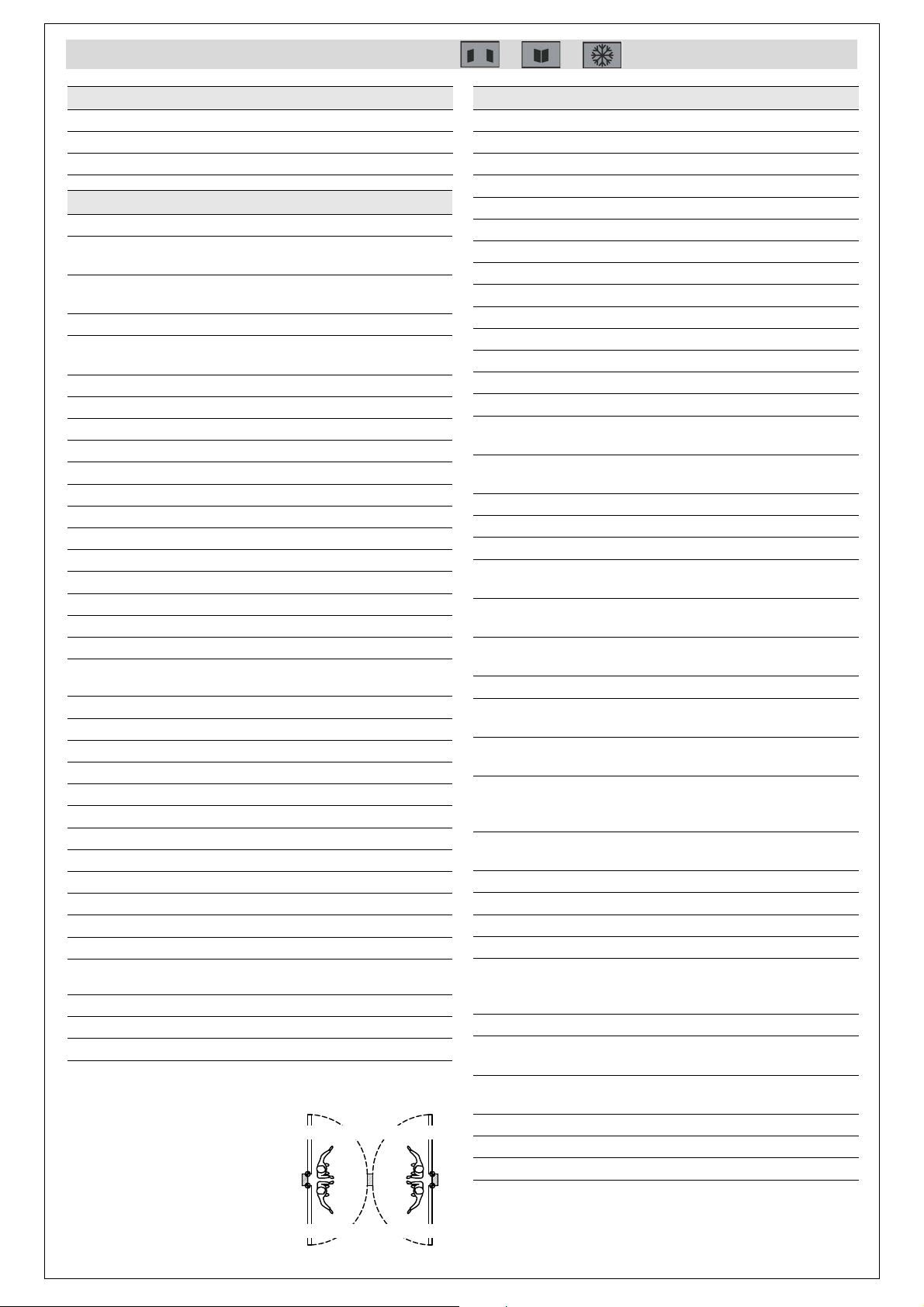
Door Handling *
Door Handling is determined by
standing your back to the
hinges. The side to which the
door normally opens (right or
left) is the opening sense.
1.1.- Setup Menu
1.1.1.- Door Learn Mode
1.1.2.- Factory Reset Restore default parameters
1.1.3- Setup Wizard Guided door configuration
1.2.- Basic Functions
1.2.1- Select Model
• Low Energy Speeds and forces limited according to
Standard EN 16005
•FullEnergy No speed and force limitations. Safety
sensors (EN 16005)
-Standard Standard swing door configuration
-Fire door Comply with fire regulations (EN
14637)
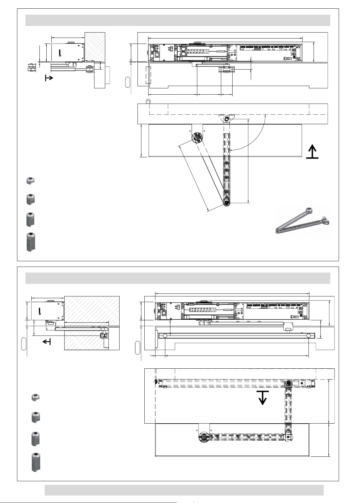
1.2.2.-Type Of Arm Define the type of arm installed
• Articulated - Push Arm
• Slide - Pull Arm
• Slide - Push Arm
1.2.3.-
Direction Of Travel Define the direction of travel
• Inwards
•Outwards
1.2.4.-
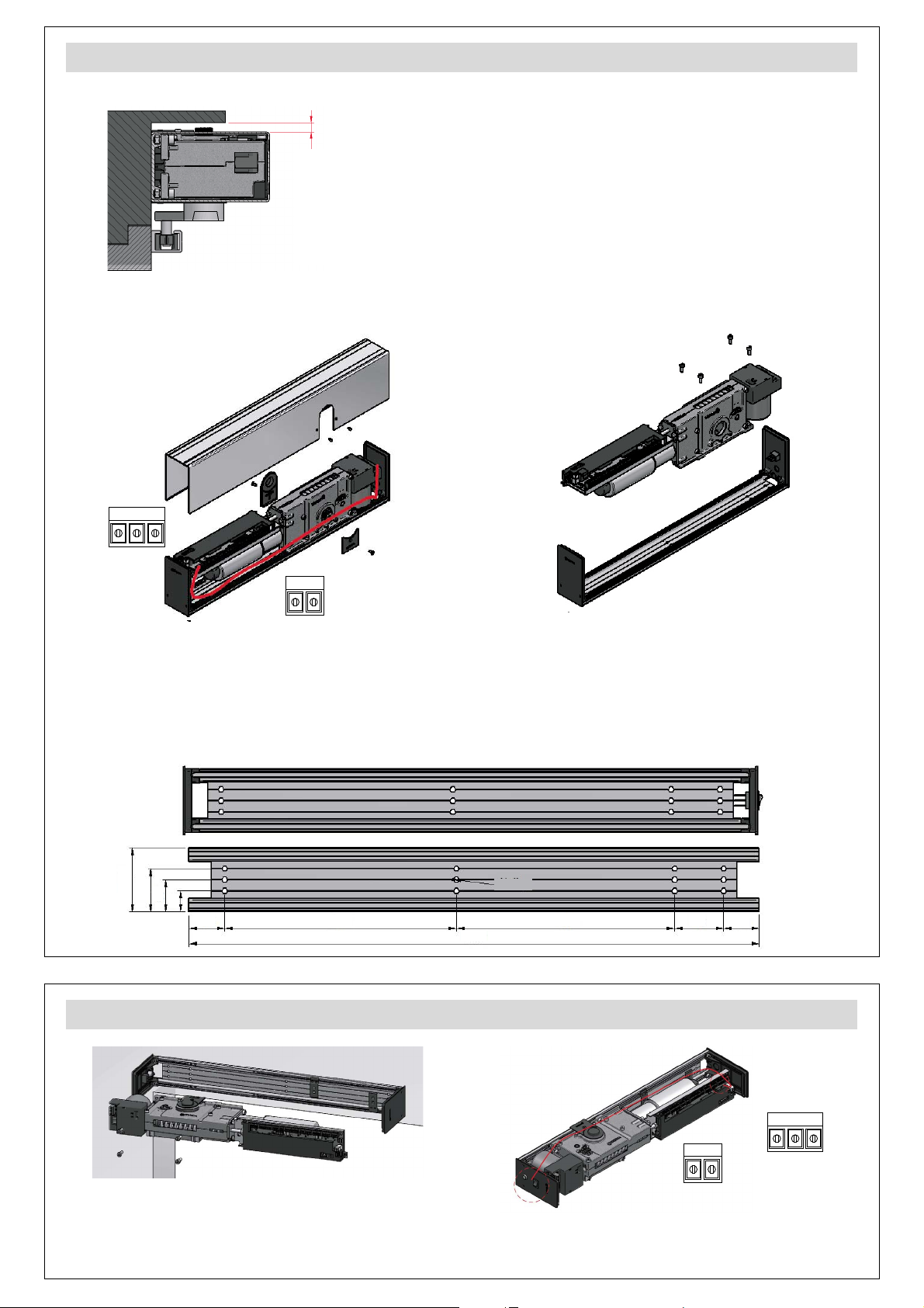
Opener Fixed To Define the operator's location
•Lintel
•Door
1.2.5.-
Door Handling* Define opening direction
• Right
•Left
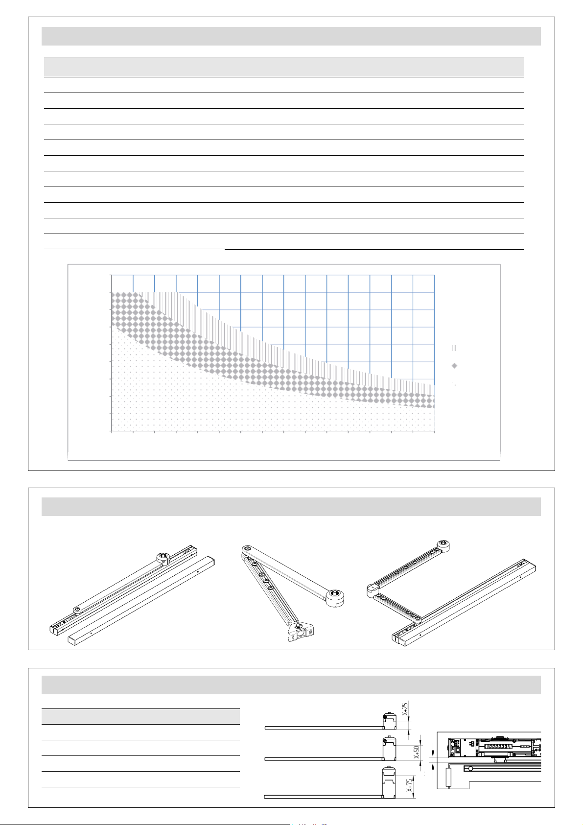
1.2.6.- Door Details Define weight and width (Obligatory
for LOW ENERGY)
• Door Weight (kg) 50 to 250 kg, def. 50 Kg
• Door Width (mm) 700 to 1.400 mm, def. 700 mm
1.2.7.- Electric Lock
• Type Define if it has electro lock or not
-Electric Strike
-Maglock
-Disabled Door with no electro lock
• Voltage Define the power supply voltage
-12V
-24V
• Opening Delay 0 to 10.000 msec, def. 0 msec
• Opening Force 0 to 5, def. 0
• Test Define if the electro lock has a test
signal
-NO
-NC
-Disabled No test
RIGHT
LEFT
LEFT
RIGHT
1.3.- Advanced Functions
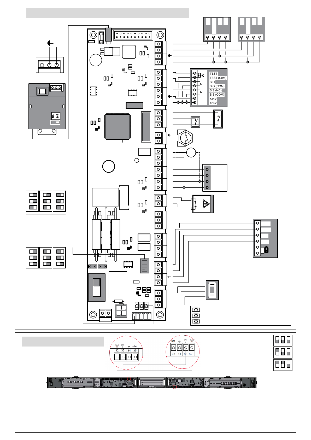
1.3.1.- Door Sync
• Select Door Define who leads the movements
-M1 Master (Leader) 1
-S1 Slave 1
•DoorSync
-Enable
·Disabled
· Enabled
-Sync Distance 0 to 45º, def. 0º
• Interlock Define interlock operation
-Enable
·Disabled
· Enabled
-Type
·Standard See “SAT Menu” in the “Installation
Guide”.
· Smart See “SAT Menu” in the “Installation
Guide”.
-Interlock Time 0 to 300 seg, def. 0 seg
1.3.2.- Automatic Mode Define operation in automatic mode
• Configuration Default configuration
-Normal Mode See “SAT Menu” in the “Installation
Guide”.
-Semi Auto Mode See “SAT Menu” in the “Installation
Guide”.
-Accessible toilets See “SAT Menu” in the “Installation
Guide”.
• Closing Device
-Motor Closing Closing with motor according to
parameters configured from selector
-Spring Closing Closing with spring. Engine released
and with passive brake
• Push&Go mode
See “SAT Menu” in the “Installation
Guide”. Def. Disabled. Degrees: 0 to
45º, def.: 0º
• Push&Close mode See “SAT Menu” in the “Installation
Guide”. Def. Disabled.
1.3.3.- Manual mode
• Normal mode
• Servo Assist mode 0 to 5, def.: 0
1.3.4.- Entrapment
• Sensitivity Level
1 to 10, def.: 5
(1 very sensitive, and 10 not very
sensitive)
• Sensitivity mode
-Standard See “SAT Menu” in the “Installation
Guide”.
-Extra Safe See “SAT Menu” in the “Installation
Guide”.
• Spring Closing
-Enabled
-Disabled
(...)

22
Tech. Support Menu ( + + ) (II)
**: See “SAT Menu” in the “Installation Guide”.
1.3.5.- Inputs / Outputs
• Input (1,2,3,4)
-Mode
· Exit only **
· Partial Mode **
· Door Open **
· Door Closed **
· Manual **
· Automatic **
· Fire door **
· Hold Open **
· Courtesy **
·Stop **
· Emergency
Locking
**
· Lock Toilet
**
· Unlock Toilet
**
· Disabled **
-Activation
· NC Normally closed
·NO Normally open
• Output (1,2)
-Mode
· Notification **
· Door Opened **
·Tamper **
· Door Closed **
· Notification **
· Toilet Occupied **
· Toilet Vacant **
· Hold open
Electromagnet
**
· Disabled **
-Activation
· NC Normally closed
·NO Normally open
• Lateral Switch Define the functions for side switch with
inputs (3, 4) in disabled mode
· Door Opened
· Door Closed
1.3.6.- Configuration
“One direction”/“Emergency” configuration
• Single Direction **
-Exit
-Entry
• Emergency **
-Configuration
· NO Pulse (Reset to restore)
· NO Continuous
· NC Pulse (Reset to restore)
· NC Continuous
· Disabled
-Mode
Type of Action
· Open Door
· Closed Door
· Manual
1.3.7.- Temperatures
• Motor Temperature -50 to 200ºC, def. 100ºC
• Driver Temperature -50 to 200ºC, def. 70ºC
• Min. Room
Temperature -50 to 200ºC, def. -20ºC
• Max. Room
Temperature -50 to 200ºC, def. 70ºC
1.4.- Sensors
1.4.1.- Activation Device
• Internal
-Configuration
·NO Signal normally open
· NC Signal normally closed
· Disabled
-Courtesy **
·Disabled
· Enabled
• External
-Configuration
·NO Signal normally open
· NC Signal normally closed
· Disabled
-Courtesy **
·Disabled
· Enabled
1.4.2.- Closing Safety Sensors **
• Configuration
-NC without test
-NC with test
-NO with test
-Disabled
• Spring closing
-Disabled
-Enabled
1.4.3.- Opening Safety Sensors **
• Configuration
-NC without test
-NC with test
-NO with test
-Disabled
• Des-Activate 30 to 90º, def.: 90º
1.5.- Movements Parameters
1.5.1.- Closing
• Speed 5 to 10 sec, def.: 7 sec
• Courtesy Speed 6 to 10 sec. def.: 10 sec
•SlowMovement
Speed
1 to 5, def.: 3; door speed in anti-
crushing movement.
• Acceleration 0 to 5, def.: 1
• Approach Position 5 to 30º, def.: 5º
• Approach Speed 1 to 5, def.: 2
(...)

23
Tech. Support Menu ( + + ) (III)
1.5.- Movements Parameters (cont.)
1.5.2.- Opening
• Speed 3 to 10 sec, def.: 5 sec
• Courtesy Speed 6 to 10 sec, def.:7 sec
•SlowMovement
Speed
1 to 5, def.: 3; door speed in anti-
crushing movement.
• Acceleration 0 to 5, def,: 3
• Approach Position 70 to 85º, def.: 80º
• Approach Speed 1 to 5, def.: 3
• Reverse Movement
-Fast Rev. Position 10 to 45º, def.: 30º
-
Slow Rev. Position
60 to 80º, def.: 70º
1.5.3.- Power
• Closed Door 0 to 10, def.: 0
• Spring Assistance 0 to 10, def.: 2
• Spring Assist. Pos.
0º to 45º, def.: 10º
• Final Push 0 to 10, def.: 1
• Push Release Door 0 to 5, def.: 0 (Off)
• Start spring closing 0 to 5, def.: 0
1.5.4.- Select times
• Opened In Normal 0 to 60 sec, def.: 1 sec
• Opened In Pulse 0 to 60 sec, def.: 1 sec
• Opened In Courtesy 0 to 60 sec, def.: 1 sec
• Change To Closed 0 to 300 sec, def.: 0 sec
1.6.- Installation Information
1.6.1.- Service Information
1.6.2.- Installation ID
1.6.3.- Commissioning Date
1.6.4.- Last Notification Code
1.6.5.- Last Service Date
1.6.6.- Sensor Status
• In Activation
• Ext Activation
• Closing Safety Sen
• Openig Safety Sen
•KB
•KC
• Electric Strike
1.7.- Service
1.7.1.- Next Service
1.7.2.- Auto Check
1.8.- Access Code Configuration
1.8.1.- Change Code
1.8.2.- Reset Code
1.8.3.- Code Activation
•Disabled
• Enabled
Warnings / Errors (I)
Type Description Possible cause Possible solution
Warning 2 Encoder failure
The motor may be
locked or the encoder
wire damaged
Analyse if the motor is locked. If the motor is free, change the encoder
wire.
Warning 3 Electrolock failureThe electrolock could
not be released
Check if the electrolock could be released manually. If it works properly
mechanically, check the configuration of the test and the test itself.
Warning 4 Flash memory
failure
The flash memory is
damaged or it is
out of date
Make a default parameters, if the warning continues, contact with the
technical support, a replacement of the electronic board could be
necessary.
Warning 5 Motor driver
temperature
The motor control
transistors are
overheated
The door will open until the temperature of the driver drops. Then it will
return to a normal operation. A reset could be done for a quick recovery.
Warning 6 Overcurrent in
the motor
There is an
overcurrent in the
motor input
Check if the motor is locked. If the motor is free, make a reset. After a
reset, if the warning continues, contact with the technical support, a
replacement of the board or the motor could be necessary.
Warning 7 Motor
temperature
The motor is
overheated
The door will stop until the temperature of the motor drops. Then it will
return to a normal operation. A reset could be done for a quick recovery.
Warning 8 Closing safety
sensor enabled
Obstacle in the
photocell detection
area
Check the proper operating of the photocell, if it works properly, remove
the obstacle. A reset could be done for a quick recovery.
Warning 9
(*)
Remote safety
closing enabled
Obstacle in the
remote photocell
detection area
Check the proper operating of the photocell, if it works properly, remove
the obstacle. A reset could be done for a quick recovery.
Warning
10
Interior radar
enabled
Obstacle in the radar
detection area
Check the proper operating of the radar, if it works properly, remove the
obstacle. A reset could be done for a quick recovery.
Warning
11
Exterior radar
enabled
Obstacle in the radar
detection area
Check the proper operating of the radar, if it works properly, remove the
obstacle. A reset could be done for a quick recovery.
Warning
12
Safety opening
sensor enabled
Obstacle in the safety
sensor detection area
Check the proper operating of the sensor, if it works properly, remove the
obstacle. A reset could be done for a quick recovery.
(*) These errors are only available when two boards are communicated by CAN protocol. (...)

24
Warnings / Errors (II)
(*) These errors are only available when two boards are communicated by CAN protocol.
Type Description Possible cause Possible solution
Warning
13 (*)
Remote safety
openingsensor
enabled
Obstacle in the safety
sensor detection area
Check the proper operating of the sensor, if it works properly, remove the
obstacle. A reset could be done for a quick recovery.
Warning
14
Internal power
source failure
One of the voltages
inside the board is out
of range
Make a reset to recover the proper functionality. If the warning persists
contact with the technical support, a replacement of the electronic board
could be necessary.
Warning
15
Motor voltage
failure
The output voltage
of the motor is out of
range
Make a reset to recover the proper functionality. If the warning persists
contact with the technical support, a replacement of the electronic board
could be necessary.
Warning
17
Main voltage
failure
Input current wrong
or power fuse failed
Check if the power input is suitable. If it is correct check the power fuse. If
both works properly, contact with the technical support, a replacement of
the electronic board or power supply could be necessary.
Warning
18
System voltage
failure
The voltage of the
system is out of range
Make a reset to recover the proper functionality. If the warning persists
contact with the technical support, a replacement of the electronic board
could be necessary.
Warning
19
Room
temperature
The working
temperature is too
high
The door will automatically go to door open until the temperature drops
below the temperature set the maximum temperature could be verify with
the digital selector and the range is also able to modify with the digital
selector.
Warning
20 Anti-crush An entrapment
occurs
Remove the obstacle or check if there is a friction in the movement of the
door.
Warning
23 Emergency The emergency signal
is enabled
Depends on the configuration of the signal, the warning will be disappear
automatically when the signal turns off or doing a reset would be necessary
to remove the warning.
Warning
24
Continuous
anti-crush
Three entrapment
occur
Remove the obstacle or check if there is a friction in the movement of the
door. A reset would be necessary to recover the proper functionality.
Warning
25
Photocell test
failure Photocell damaged
Check if the photocell configuration coincides with its configuration in the
digital selector. If it is correct, contact with the technical support, a
replacement of the photocell could be necessary. Temporally, a
configuration normally closed without test could be used.
Warning
26 (*)
Remote
photocell test
failure
Photocell damaged
Check if the photocell configuration coincides with its configuration in the
digital selector. If it is correct, contact with the technical support, a
replacement of the photocell could be necessary. Temporally, a
configuration normally closed without test could be used.
Warning
27
Safety sensor
test failure
Safety sensor
damaged
Check if the sensor configuration coincides with its configuration in the
digital selector. If it is correct, contact with the technical support, a
replacement of the sensor could be necessary. Temporally, a configuration
normally closed without test could be used.
Warning
28 (*)
Remote safety
sensor test
failure
Safety sensor
damaged
Check if the sensor configuration coincides with its configuration in the
digital selector. If it is correct, contact with the technical support, a
replacement of the sensor could be necessary. Temporally, a configuration
normally closed without test could be used.
Warning
29 (*)
Warning on the
other door
operator (M1 or
S1)
If the display shows
M1 at the bottom, it
means there is a
warning in S1 (or vice
versa)
Go to the "Select Door" menu and switch from M1 to S1 (or vice versa) to
check the error in the other door operator
Warning
30
Motor or brake
activation
failure
Electronic board
damaged or motor
unplugged
Check if the motor is plugged, then make a reset to repeat the test. If the
warning persists contact with the technical support, a replacement of the
electronic board or motor could be necessary.
Warning
31 Relay K2 fail The relay is damaged Switch off and switch on the electronical board and check if the relay can
commute.
Warning
32 Relay K3 fail The relay is damaged Switch off and switch on the electronical board and check if the relay can
commute.
Warning
34 (*)
Failure in
communication
There is a
communication error
between two
operators
Check if the communication wire is installed correctly. Make a reset to
recover the proper functionality. If the warning persists check the
configuration of the boards.
Warning
35
Incomplete
reset
The opener cannot
make a reset
Check if the door is blocked with an obstacule or if there is a friction in the
movement of the door and try to make a reset again. The door must try to
make a reset three times.
Warning
36
Electrolock
release failure
The electrolock is
blocked
Adjust the electrolock mechanically. Configure the help parameters for
electrolocks: "Delay time" and "Reverse force".
Warning
37
Safety sensor
auto-
configuration
incorrect
Auto-configured
position does not
match in the different
movements
Check the configured disable position in the “Opening safety sensors
(SIO)” menu. The warning disappears once validated by pressing OK in this
menu.
Table of contents
Other Erreka Door Opening System manuals
Popular Door Opening System manuals by other brands

WSS
WSS SPRINT NOVA 80 Assembly and operating instructions

Assa Abloy
Assa Abloy Corbin Russwin DC8210 Series installation instructions

Raynor
Raynor ControlHoist 2.0 STANDARD Installation instructions and user guide

JCM Technologies
JCM Technologies KEEROLL user manual

golmar
golmar K-ACCESS PAC-90 quick start guide

Assa Abloy
Assa Abloy Norton 9500 Series installation instructions