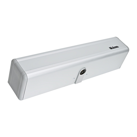
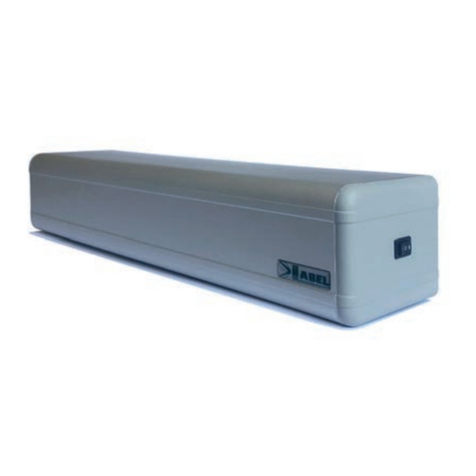
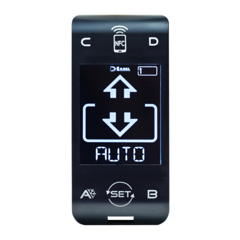
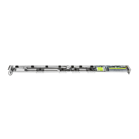
Label NEXT 120s User manual

INSTALLATION
MANUAL
NEXT 120S - EN - Rel.1.2- 02/2021 - CD0752EN
NEXT®120S
Automation for
automatic swing doors
English
TRANSLATION OF THE ORIGINAL INSTRUCTIONS
EN


CONTENTS:
GENERAL SAFETY WARNINGS 4
GENERAL SAFETY OBLIGATIONS 4
1) DESCRIPTION OF THE MODELS 5
2) TECHNICAL SPECIFICATIONS 5
3) NEXT 120S AUTOMATION COMPONENTS 6
4) PRELIMINARY CHECKS 6
5) PREPARATION AND INSTALLATION 7
5.1) TOOLS REQUIRED: 7
5.2) PREPARATION OF THE AUTOMATION 7
5.3) INSTALLATION OF AUTOMATION NEXT 120S 8
5.4) SPRING LOADING PROCEDURE 8
5.5) ARM REMOVAL 9
6) TECHNICAL DRAWINGS 10
6.1) SLIDING PULL ARM NEXT120‑BDT 10
6.2) SLIDING PUSH ARM NEXT120‑BDS 11
6.3) ARTICULATED PUSH ARM NEXT120‑BAS 12
6.4) ELBOW SLIDING PULL ARM NEXT120‑B150 13
6.5) ELBOW SLIDING PULL ARM NEXT120‑B250 14
6.6) NEXT120‑BAS LEAF MOUNTING 15
6.7) SHAFT EXTENSION PIVOT NEXT‑EXT 15
7) ELECTRIC CONNECTIONS 17
8) SAFETY SENSORS 20
8.1) SAFETY SENSOR OA‑EDGE T 20
8.2) FLAT SCAN SAFETY SENSOR 20
9) DIGITAL SELECTOR ET‑DSEL – PURPOSE AND CONNECTIONS 21
10) COMMISSIONING OF THE AUTOMATION (INITIAL SETUP) 22
10.1) FIRST START OF THE DIGITAL SELECTOR ET‑DSEL 22
10.2) SERIAL COMMUNICATION SETTINGS 22
10.3) INITIAL SETUP 23
10.4) FUNCTIONAL TESTING 25
10.5) INPUT DIAGNOSTICS 25
11) PROGRAM SELECTORS 26
11.1) MANUAL PROGRAM SELECTORS 26
11.2) MECHANICAL KEY SELECTOR EV‑MSEL 26
11.3) DIGITAL SELECTOR ET‑DSEL – USED AS PROGRAM SELECTOR 27
12) BATTERY PACK NEXT‑BAT120S 29
13) GENERAL PROGRAMMING MENU 30
14) FUNCTIONS AND SETTINGS 31
14.1) FUNCTIONS SETTING 31
14.2) POTENTIOMETER ADJUSTMENT 31
15) LANGUAGE 39
16) PASSWORD MANAGEMENT 39
16.1) HOW TO CHANGE THE TECHNICAL PASSWORD 40
16.2) HOW TO CHANGE THE PRIMARY PASSWORD 40
16.3) HOW TO CHANGE THE SERVICE PASSWORD 41
16.4) ENABLING USER PASSWORD USAGE (PRIMARY AND SERVICE) 42
16.5) DISABLING USER PASSWORD USAGE 42
17) SELECTOR OPTIONS 43
18) INFORMATION AND EVENT MEMORY 44
19) MAINTENANCE 47
19.1) PLUG AND PLAY 47
20) APPLICATIONS WITH ELECTRIC LOCK 48
20.1) ELECTRIC LOCK / ELECTRIC STRIKE 48
20.2) ELECTROMAGNET 48
21) DUAL LEAF DOOR 49
21.1) DUAL LEAF ELECTRIC SETUP 49
21.2) DUAL LEAF DOOR COMMISSIONING 49
21.3) FUNCTIONAL TESTING 52
21.4) PARTIAL OPENING 52
21.5) CONSIDERATIONS ABOUT THE USE OF THE SELECTOR ET‑DSEL OF THE TWO‑LEAF DOOR 53
21.6) MASTER / SLAVE INPUTS DIAGNOSTICS 53
22) NEXT‑RX RADIO RECEIVER 54
23) COURTESY MODE FOR DISABLED 55
24) INTERLOCK SYSTEM 56
24.1) ELECTRICAL CONNECTION FOR INTERLOCK 56
24.2) OPERATION OF THE INTERLOCK SYSTEM 57
24.3) INTERLOCK APPLICATION WITH ELECTRIC LOCKS DISABLED WITH CLOSED DOORS 57
25) PRIVACY FUNCTION 58
25.1) ELECTRICAL CONNECTIONS 58
25.2) PRIVACY SYSTEM SETTINGS 59
25.3) SETTINGS 59
26) MEANING OF BUZZER AUDIBLE SIGNALS 60
27) MAINTENANCE PROGRAM 60
DECLARATION OF INCORPORATION OF PARTLY ASSEMBLED MACHINERY 61

4
GENERAL SAFETY WARNINGS
Carefully read this instruction manual for the safe installation and operation of the automatic door.
Improper installation and incorrect use of the product could cause serious injury.
Keep the instruction manual for future reference.
The installer must provide all the information about operation and provide the system user with the user manual delivered with the
product.
MEANING OF THE SYMBOLS USED IN THESE INSTRUCTIONS
DANGER:
Notication of dangerous situations that could cause material damage and personal injury.
WARNING:
Identies the procedures that must be understood and followed mandatorily in order to avoid damage to the product or
malfunctions.
NOTE:
Highlights important information.
GENERAL SAFETY OBLIGATIONS
The mechanical and electric installation must be performed by specialised personnel in accordance with the applicable
directives and regulations.
The installer must make sure that the structure to be automated is stable and robust and, if necessary, make structural
modications to make it so.
Keep product and packaging materials out of children's reach, as they might be a source of danger.
Do not let children stay or play within the operating range of the door.
This product is designed and built exclusively for the purpose described in this documentation. Any other use that is not specically
indicated could adversely impact the condition of the product and the safety of people.
Label accepts no responsibility for incorrect product installation and usage, as well as for any damage caused by changes made without
its prior consent.
Label is not responsible for the construction of the frames to be motorised.
The IP32 protection class requires that the automation is installed only on the inner side of buildings.
This product cannot be installed in explosive environments or atmospheres, or in the presence of ammable gases or fumes.
Make sure that the characteristics of the electric distribution network are compatible with the technical data indicated in this manual and
that upstream of the system there is an omnipolar switch with an opening distance of the contacts of at least 3mm and a residual current
device.
The automatic door must be checked, started up, and tested by personnel skilled and trained about the product.
A technical dossier must be compiled for every automation, as established in the Machinery Directive.
Disconnect the power supply before working on the automation and before opening the cover.
Maintenance is of fundamental importance for the proper operation and safety of the automation. Check the eciency of all parts every
six months.
Use only original spare parts for maintenance and when replacing product components.
Cleaning operations must be performed with the power supply disconnected, using a damp cloth. Do not deposit or let water or other
liquids penetrate into the automation or the accessories that are part of the system.
It is recommended to subscribe a maintenance contract.
The automatic swing doors must be designed and installed so as to protect users against the risk and danger of crushing,
impact, and shearing between the leaf and adjacent parts near the door outline.
The person responsible for starting-up the automation must perform a risk assessment based on the place of installation
and the type of users that could use the automatic door.
The automation NEXT 120S, as provided for by the standard EN16005, must be equipped with the safety devices (sensors)
compliant with the standard EN12978.
A = Main closing edge
B = Secondary closing edge
C = Opposite closing edge
The crushing and shearing dangers on the secondary closing edge must be protected structurally or
by means of additional safety provisions (e.g., rubber covers).
Any residual risks must be properly highlighted.

5
1) DESCRIPTION OF THE MODELS
NEXT 120S is an automation designed to open swing doors with brushless motor and closing spring.
The electronic control equipment is located inside the automation.
A list of the swing door automation models NEXT 120S produced by Label is provided below:
NEXT 120S = automation for single leaf
NEXT 120SB = automation with battery for single leaf
NEXT 120SD = automation for double leaf
NEXT 120SDB= automation with battery for double leaf
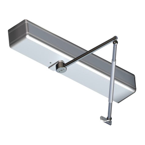
The automation NEXT 120S can be used with slide pull arm, or with articulated push arm.
The automation must be installed in indoor environments.
All automation models are reversible, so in case of power failure it is possible to open the door manually.
Before starting installation, refer to the technical drawings in paragraph 6; for each type of arm they include the application design with
installation dimensions and the chart that, depending on the automation model, provides the weight limits based on the length of the door
leaf.
The technical data provided in the drawings refers to a typical installation, but may be inuenced by variables inherent to each closing,
such as friction, environmental conditions, alignment of the leaf hinges, etc....
2) TECHNICAL SPECIFICATIONS
POWER SUPPLY 115/230V~, 50‑60Hz
POWER 50W
TORQUE 25 Nm
LEAF MAX. WEIGHT 120 Kg
POWER SUPPLY OF EXTERNAL ACCESSORIES 24Vdc, 0.8A
EQUIPMENT CLASS class II
ELECTRIC MOTOR Brushless 24Vdc
AUTOMATION SIZE (LxHxD) 520 x 60 x 74 mm
STAND-BY CONSUMPTION 5W
AMBIENT TEMPERATURE ‑15°C +50°C
FREQUENCY OF USE continuous
LIMIT SWITCH AND ANTICRUSH SAFETY controlled by encoder
REACTION TO OBSTACLES reversal of direction
OPENING TIME FOR 90° 2 ‑ 12 seconds adjustable
CLOSING TIME FOR 90° 4 ‑ 12 seconds adjustable
PAUSE TIME 0 ‑ 60 seconds adjustable
SOUND PRESSURE EMISSION LpA < 70dB (A)

6
FIXING PLATE
PLASTIC PLATE
MANUAL PROGRAM SELECTOR
CLOSING SPRING
SWITCHING POWER SUPPLY NEXT-PW75
LOGIC BOARD NEXT-L120S
GEARMOTOR WITH ENCODER
BATTERY NEXT-BAT120S
3) NEXT 120S AUTOMATION COMPONENTS
4) PRELIMINARY CHECKS
Before installing the automation, verify the following requirements:
• The support structure of the automation should be rm, with no signicant deformation.
• The structure of the leaf must be rigid and strong.
• The leaf hinges must be adequate and in good condition.
• The length and weight of the leaf must be within the operating limits of the automation.
• The movement of the leaf must be smooth and free of friction throughout the run.
• The door requires mechanical stops, consisting of a mechanical stop in open position and a nal stop in closed position.
The mechanical opening stop is not supplied with the automation.

7
5) PREPARATION AND INSTALLATION
5.1) TOOLS REQUIRED:
Tape measure, drill, level, at-head screwdriver, cross-head screwdriver,
Allen wrenches with handle (sizes 3 ‑ 4 ‑ 5).
5.2) PREPARATION OF THE AUTOMATION
Remove the cover retaining screws.
Pull the cover out of its housing by releasing it at its ends and pulling it
upwards (g. 1).
Remove the plastic side caps from the plate by loosening the socket
head cap screws M5x8 (g. 2).
Remove the enclosure of the electronic control unit from the plate by
unscrewing the two countersunk hex head screws M5x8 (g. 3).
Remove the motor/spring mechanic unit from the plate by unscrewing
the two socket head cap screws M5x60 (g. 4).
1
2
3
4

8
5.3) INSTALLATION OF AUTOMATION NEXT 120S
Depending on the type of arm to be used and the opening direction of the door, refer to the relevant technical drawing (para. 6 and sub-
paragraphs), which shows the installation dimensions.
Mount and secure the automation plate using screws and xings suitable for the type of support (not supplied by Label).
The automation NEXT-120S provides the possibility of connecting the arm pin on
both sides of the mechanical body.
The arrow on the shaft output of the mechanical body indicates the opening
direction of the automation (Fig. 5).
Locate the correct side for connecting the pin according to the type of arm used
(pull or push) and the door opening direction.
WARNING!!!
The opening direction of the automation must match the opening direction of the
door.
If the arm rotates in the opposite direction to the opening direction, it can result in
irreversible damage to the automation latch spring.
For pull to open doors, reinstall the mechanical motor/spring unit onto the plate
with the letter A on the label visible from above, indicating that the automation
NEXT-120S is ready for installation on pull to open doors (Fig.A).
The arm models suitable for pull to open doors with wall mounted automation are
NEXT120‑BDT, NEXT120‑B150, NEXT120‑B250.
If you need to install the automation on push to open doors, reinstall the mechanical
motor/spring unit onto the plate on the opposite side with the letter B on the label
visible from above, indicating that the automation is ready for installation on push
to open doors (Fig.B).
The arm models suitable for push to open doors with wall mounted automation are
NEXT120‑BAS, NEXT120‑BDS.
Install the motor/spring mechanic unit on the plate using the four socket head cap
screws M5x60.
Reinstall the enclosure of the electronic control unit and the plastic side caps on
the automation plate.
The automation NEXT 120S is supplied with the closing spring unloaded.
After installing the automation NEXT 120S, the spring loading procedure must
be performed before inserting the arm pin into the shaft output of the automation.
5.4) SPRING LOADING PROCEDURE
Carefully follow the following steps to load the spring of the automation NEXT 120S:
a) make sure that the arm is not inserted into the automation.
b) Select position "II" on the manual selector located on the side cap of the automation.
c) Supply the automation with 230V (see para. "Electrical connections" about how to connect the power terminal).
The control unit buzzer will emit 5 fast beeps.
d) Press and hold the button PS1 (start) on the electronic control unit NEXT‑L120S.
The buzzer of the control unit will emit 5 beeps and the gearmotor will perform a slow rotation of one turn in the direction of the arrow.
Once the maximum spring load position has been reached, the motor will stop and some beeps will sound.
Release the button PS1 (see NOTE 1).
WARNING! DO NOT REMOVE 230V POWER TO PREVENT SPRING UNLOAD.
e) Insert the arm pin into the shaft output of the automation, ensuring that the plastic plate is clipped onto the mechanical body and
secure it by tightening the central screw rmly (see NOTE 2).
f) Remove power from the automation and manually check the door movement for the entire run.
The leaf must close by means of the closing spring, even after a few degrees of opening, at a limited speed thanks to the passive
braking control circuit.
g) Start the automation by following the procedure described in paragraph "Initial SETUP of the automation" and selecting COMPLETE
SETUP.
NOTE 1: if during the spring load turn described in item d) above the button PS1 is released, the movement stops. In this case, press
PS1 again to resume the loading turn.
To slowly unload the spring, select position 0 on the manual selector.
To quickly unload the spring back to its initial position, select position I.
NOTE 2: When choosing the spring closure force, consider the following:
connect the arm with door open to achieve minimum force (recommended solution);
connect the arm with door closed for maximum force:
connect the arm with door at half run for intermediate force.
Fig.A
Fig.B
Fig.5
9
5.5) ARM REMOVAL
If it is necessary to remove the arm in order to release the leaf from the automation, carry out this operation only after
removing the power supply.
Once the arm is removed, the automation spring will fully unload.
The following steps must be performed using the digital selector to restore the automatic door operation before reinstalling the arm:
a) reset the previous setup by accessing the "Maintenance" section of the general programming menu and select the item "General
Reset" (see the "Maintenance" paragraph);
b) repeat the spring loading procedure in the following order; select position "II" on the manual selector located on the automation side
cap;
c) Press and hold the button PS1 (start) on the electronic control unit NEXT‑L120S.
The buzzer of the control unit will emit 5 beeps and the gearmotor will perform a slow rotation of one turn in the direction of the arrow.
Once the maximum spring load position has been reached, the motor will stop and some beeps will sound.
Release the button PS1.
WARNING! DO NOT REMOVE 230V POWER TO PREVENT SPRING UNLOAD.
d) Now insert the arm pin into the shaft output of the automation, ensuring that the plastic plate is clipped onto the mechanical body and
secure it by tightening the central screw rmly.
e) Remove power from the automation and manually check the door movement for the entire run.
The leaf must close by means of the closing spring, even after a few degrees of opening, at a limited speed thanks to the passive
braking control circuit.
f) Restart the automation by following the procedure described in paragraph "Initial SETUP of the automation" and selecting PARTIAL
SETUP.
g) At the end of the partial set-up, the automation will operate in the same mode and with the same parameters previously set.

10
X = 51mm
X = mm
6) TECHNICAL DRAWINGS
6.1) SLIDING PULL ARM NEXT120-BDT
STANDARD
TAPERED PIN
NEXT-EXT
EXTENSION
TAPERED PIN

11
X = 36mm
X = 6mm
6.2) SLIDING PUSH ARM NEXT120-BDS
STANDARD
TAPERED PIN
NEXT-EXT
EXTENSION
TAPERED PIN

12
x
X = 36mm
X = 6mm
6.3) ARTICULATED PUSH ARM NEXT120-BAS
STANDARD
TAPERED PIN
NEXT-EXT
EXTENSION
TAPERED PIN

13
X = 91mm
X = mm
6.4) ELBOW SLIDING PULL ARM NEXT120-B150
STANDARD
TAPERED PIN
NEXT-EXT
EXTENSION
TAPERED PIN

14
X = 91mm
X = mm
6.5) ELBOW SLIDING PULL ARM NEXT120-B250
STANDARD
TAPERED PIN
NEXT-EXT
EXTENSION
TAPERED PIN

15
X = 36mm
X = 6mm
6.6) NEXT120-BAS LEAF MOUNTING
6.7) SHAFT EXTENSION PIVOT NEXT-EXT
NEXT-EXT
Shaft extension pivot 25mm.
Applicable on all types of arms to increase the distance between automation and arm.
STANDARD
TAPERED PIN
NEXT-EXT
EXTENSION
TAPERED PIN

16
NOTE:
The grey part indicates the
monitoring zone of radars
and sensors.
The number of cables and
the relevant section in mm is
indicated for every device.
1 EXTERNAL RADAR (4x0.25mm)
2 INTERNAL RADAR (4x0.25mm)
3 OPENING DEVICE (2X0.25mm)
4 PROGRAM SELECTOR (4X0.25mm)
5 CLOSURE SAFETY SENSOR (6x0.25mm)
6 OPENING SAFETY SENSOR (6x0.25mm)
7 AUTOMATION NEXT 120S (mains power 2x0,75mm)
8 ELECTRIC LOCK (2x0.5mm)
9 FLOOR STOP
• The power supply line must be protected against short circuit and leakage to ground.
• On the power supply mains, provide an omnipolar switch/cut o device with contact opening distance of at least 3 mm
• Use self-extinguishing cables for electrical connections.
• Separate the mains power supply line from the very low voltage line control unit relative to control and safety accessories.
• On the plastic side caps of the automation NEXT 120S there are the holes that must be broken open, through which the electric
cables must be inserted.
The installer must take care to secure the power supply cable inside the automation and, in particular, to limit the stripping of the
primary sheath of the cable, so that the surface and air distances do not reduce if a wire comes o the terminal.
• If the automation is installed on a leaf, make the electrical connections using a junction box with suitable commercially available
hoses and exible joints.
ELECTRIC SETUP

17
7) ELECTRIC CONNECTIONS
POWER SUPPLY CUT-OFF
SWITCH
OA-EDGE-T...L
LEFT SENSOR
OA-EDGE-R...R
RIGHT SENSOR
NEUTRAL
LIVE
230 Vac
The lens with the TX marking must be positioned
corresponding to the end of the door.
2
RAD.IN
1
RAD.EX
0
COMMON
0
COMMON
MANUAL PROGRAM
SELECTOR
0
(-)
0
(-)
24
24V (+)
24
24V (+)
INTERNAL RADAREXTERNAL RADAR
COMMON 0
AUX1
COMMON
AUX2
OPEN 3
CLOSING SIDE SENSOR
SWITCH B4=ON
OPENING SIDE SENSOR
SWITCH A7=ON
SWITCH B4=OFF
COMMUNICATION CABLE
OA-EDGET SAFETY SENSORS
OUTPUTS
MAIN SENSOR
SECONDARY SENSOR
CLOSING SIDE OPENING SIDE
POWER TEST
PURPLE
SEN./CL. 7
COMMON 0
SEN./OP. 6
COMMON 0
0 (GND)
YELLOW
GREEN
GREY (DO NOT CONNECT)
BLUE
PINK
BLACK T (TEST)
BROWN 0 (-)
WHITE 24 24V(+)
RED (DO NOT CONNECT)
DIGITAL SELECTOR ET-DSEL
230 Vac

18
FASE
NEUTRO
POWER SUPPLY TERMINAL 230V
STEP 1 STEP 2 STEP 3
Separate view of the parts Connection to the power supply terminal Insertion of wired terminal into the
protective enclosure
STEP 4 STEP 5
Closing of the protective enclosure Plug-in connection to the 230V input connector of the control unit of NEXT 120S

19
Terminals 0-5 AUX 1 (manual switch)
Terminals 0-4 AUX 2 (manual switch)
Terminals 0-3 OPEN input (N.O. contact if F21 = ON; N.C. contact if F21 = OFF)
Terminals 0-2 internal radar input (N.O. contact)
Terminals 0-1 external radar input (N.O. contact)
Terminals 0-6 input of opening safety sensor (N.C. contact)
Terminals 0-7 input of closing safety sensor (N.C. contact)
Terminals 0-24 24Vdc output (0 negative, 24V positive)
Terminals 0-T Test for safety sensors (0 negative, T positive)
Terminals S-24V
Open Collector output.
The mode of operation depends on the multi-function F41m.
Terminals C - NO - NC
(Common, normally open, normally closed)
Potential free contact of relay RL1 to connect the electric lock.
ELECTRICAL CONNECTIONS OF NEXT-L120S CONTROL UNIT TERMINALS

20
8) SAFETY SENSORS
This section describes how to connect and setup correctly some of the safety sensors compliant with the standard EN12987 available on
the market, to ensure a safety level which corresponds to PL = c, Category 2 as provided for by the standard EN16005.
8.1) SAFETY SENSOR OA-EDGE T
This section describes how to connect and setup the safety sensors in accordance with the standard EN16005.
WIRING CONNECTION OF SENSOR OA-EDGE T CONNECTION OF AUTOMATION NEXT 120S WIRING
Wiring between the sensor and the terminal of the control unit NEXT-L120S
1. WHITE (+) Power supply TERMINAL 24 (+)
2. BROWN (‑) Power supply TERMINAL 0 (‑)
3. GREEN COM (Closing side) TERMINAL 0 COM
4. YELLOW N.C. (Closing side) TERMINAL 7 Closing safety sensor
5. GREY N.O. (Closing side) do not connect
6. PINK COM (Opening side) TERMINAL 0 COM
7. BLUE N.C. (Opening side) TERMINAL 6 Opening safety sensor
8. RED N.O. (Opening side) do not connect
9. BLACK (+) Test input TERMINAL T TEST(+)
10. VIOLET (‑) Test input TERMINAL 0 GND (‑)
DIP SWITCH SETTING ON OA-EDGE T PARAMETERS ON DIGITAL SELECTOR ET-DSEL
A7 = ON Low level test input.
A8 = OFF Input test delay 10msec.
B4 = OFF Sensor installed on opening side.
B4 = ON Sensor installed on closing side.
F11 (S05) = ON Closing safety sensor
F12 (S06) = ON Opening safety sensor
F13 (S07) = ON TEST of opening safety sensor
F14 (S08) = ON TEST of opening safety sensor
F15 (S09) = OFF Test level LOW
8.2) FLAT SCAN SAFETY SENSOR
CONNECTION OF FLAT SCAN SENSOR WIRING CONNECTION OF AUTOMATION NEXT 120S WIRING
Wiring between the sensor and the terminal of the control unit NEXT-L120S
1. GREEN (+) Power supply TERMINAL 24 (+)
2. BROWN (‑) Power supply TERMINAL 0 (‑)
3. YELLOW COM (Opening side) TERMINAL 0 COM
4. WHITE N.C. (Opening side) TERMINAL 6 Opening safety sensor
5. PINK COM (Closing side) TERMINAL 0 COM
6. GREY N.C. (Closing side) TERMINAL 7 Closing safety sensor
7. RED (+) Test input TERMINAL T TEST(+)
8. BLUE (‑) Test input TERMINAL 0 GND (‑)
DIP SWITCH SETTING ON FLAT SCAN PARAMETERS ON DIGITAL SELECTOR ET-DSEL
DIP 1 ON Sensor installed on opening side.
DIP 1 OFF Sensor installed on closing side.
F11 (S05) = ON Closing safety sensor
F12 (S06) = ON Opening safety sensor
F13 (S07) = ON TEST of opening safety sensor
F14 (S08) = ON TEST of opening safety sensor
F15 (S09) = OFF Test level LOW
This manual suits for next models
3
Table of contents
Other Label Door Opening System manuals

Label
Label NEPTIS/LE User manual

Label
Label Neptis SMP User manual

Label
Label ETERNA 70 User manual

Label
Label NEXT 75 User manual

Label
Label EVOLUS Manual

Label
Label T-NFC User manual

Label
Label NEPTIS PLUS User manual

Label
Label ETERNA 90 EASY User manual

Label
Label Neptis SLT-B User manual

Label
Label NEXT 75 User manual
Popular Door Opening System manuals by other brands

Entrematic
Entrematic EMSL user manual

Power Master
Power Master T Installation and owner's manual

Entrematic
Entrematic Ditec VALLOKA installation manual

Entrematic
Entrematic Ditec VALLOKB installation manual

DoorHan
DoorHan ARM 320 Installation and operating manual

Hettich
Hettich Easys 200 operating instructions