tormek SVD-185 User manual

75
Gouge Jig SVD-185
Grinding direction:
Away from the edge.
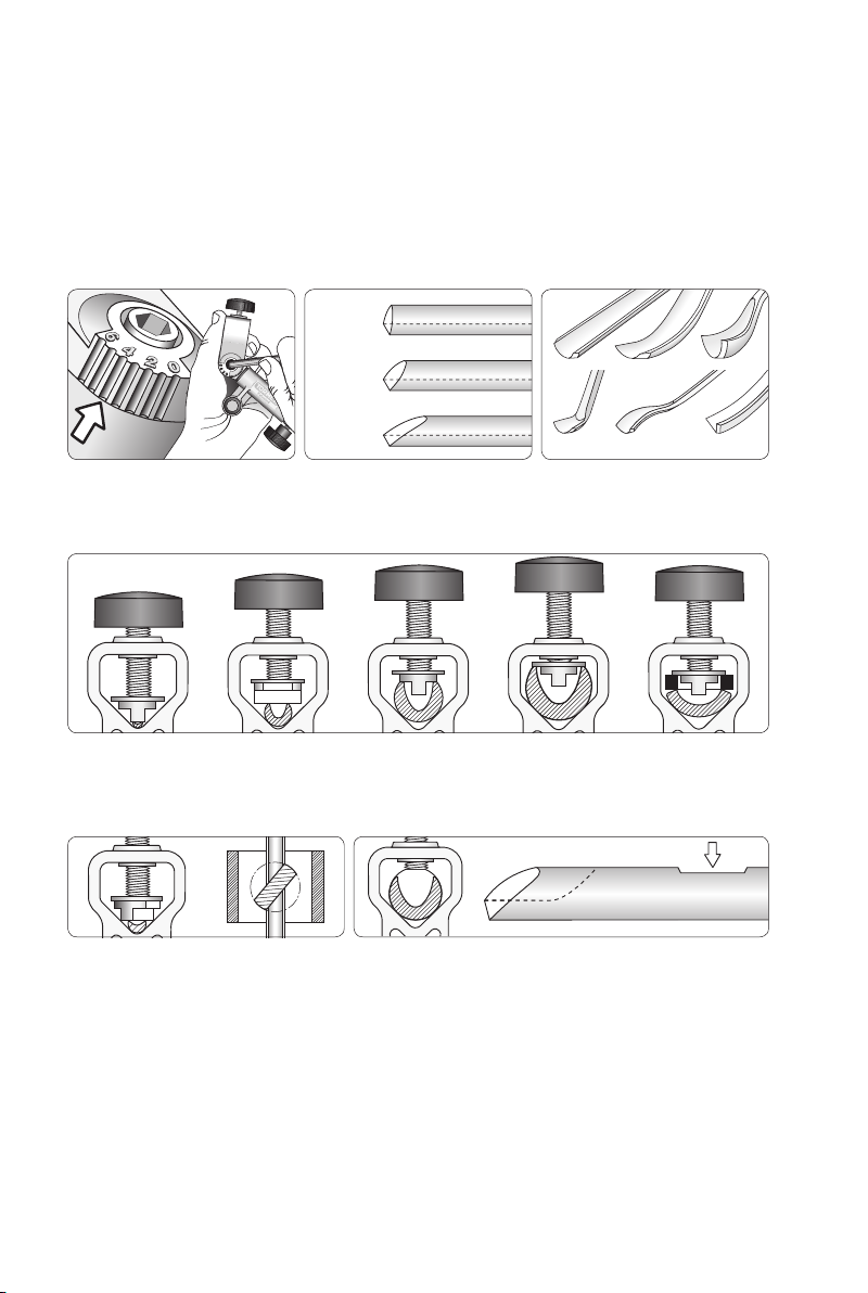
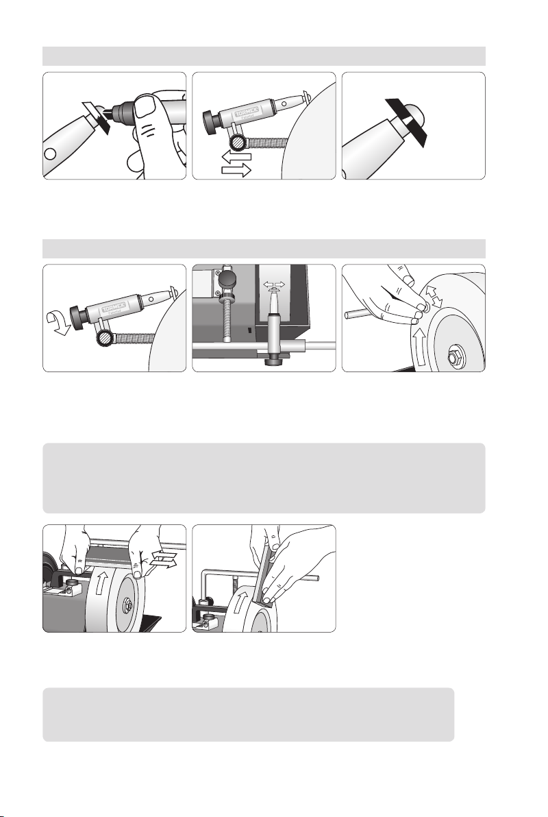
Design
The jig comprises a tool holder (1) which runs in a sleeve (2). The tool is aligned with a disc
(4) and tightened with a knob screw (5). There is a washer (6) for wide gouges. The stop ring
(7) can be set for a convex bevel with a screw (8).
The tool holder can be set in any position from 0 to 6 with the 5 mm Allen key (9). The setting
can be noted on a special prole label (10), which is attached to the ferrule. A special pen,
which works on these labels is included (11). For turning cutters there is a shaft (12) with a
mounting screw (13) and a 2,5 mm Allen key (14).
Positioning of Machine
TURNING TOOLS
Bowl gouges
Spindle gouges
Turning cutters
CARVING TOOLS
Curved gouges
Spoon-shaped gouges
Back bent gouges
Down bent gouges
Curved V-tools
Max tool width 25 mm (1").
76
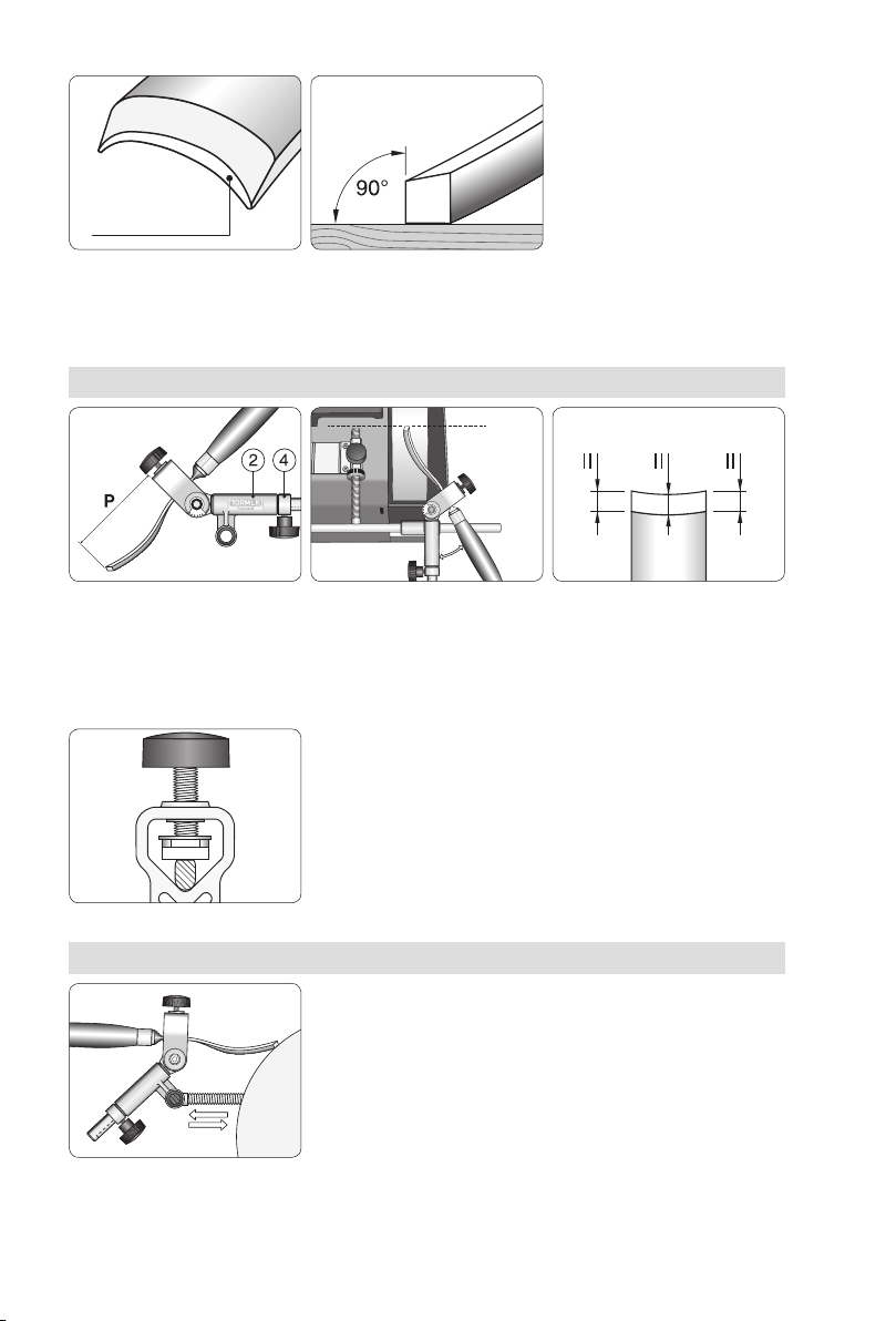
The special locking disc fits any size of tool, which is automatically aligned in the same position
every time it is mounted. The disc can be positioned either along (a) or across (b) the tool. For wide
spindle gouges there is a removable washer, which fits on the disc (c).
Turning Gouges and Carving Tools
You can grind turning gouges with the so called ngernail shape as well as carving gouges
with various shapes. You can also grind straight and curved V-tools.
The jig causes the tool to move towards the grindstone in a special way, according to the set-
ting selected from 0 to 6. This means, that for turning gouges you can decide the maximum
length of the side edges. For curved carving gouges, which are not ground with a ngernail
shape, the jig setting compensates for the shape of the shank.
The jig can be set from 0 to 6,
which permits the grinding of …
… turning gouges with various
lengths of side bevels and …
… carving gouges with various
shapes and V-tools.
The disc also works if placed diagonally.
Section seen from above.
For a large gouge with a short flute the locking disc is
removed. Flatten the top surface of the shank with a file for
repeatable alignment.
abaac
77
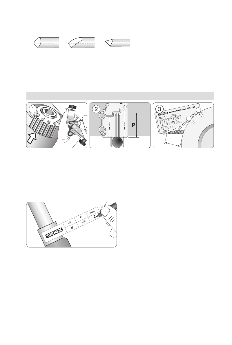
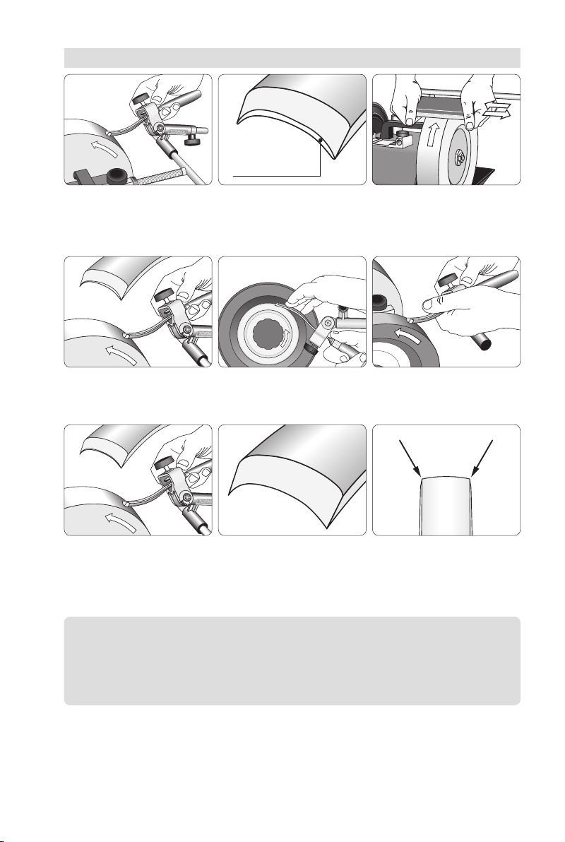
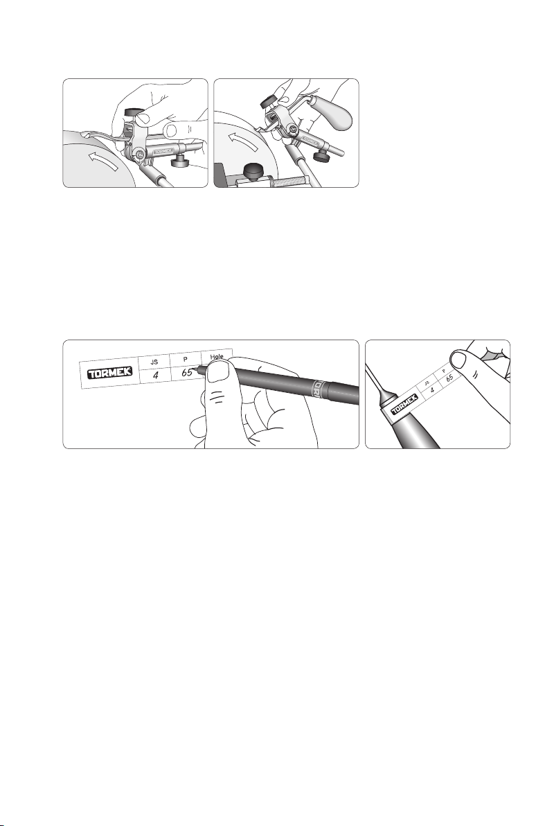
Turning Gouges
Note the settings on the Profile
Label and put it in on the ferrule.
Aset of labels comes with the jig.
The protrusion of the
toolinthejig, P.
The setting of the jig, JS. Universal Support position.
Use hole A or hole B.
Shaping
The jig positions the gouge on the grindstone so that you can get a specic and repeatable
grinding at any point along the bevel. This enables you to get an even, single bevel around
the entire prole from the left to the right wing.
With the Turning Tool Setter TTS-100 you control these factors. Select the prole you want
from the chart on the next page and use the three settings, which give that shape. Note the
settings on the Prole Label and put it on the ferrule. After the initial shaping you can exactly
replicate your favourite shape at every sharpening in less than a minute.
These three factors determine the geometry of a gouge
78
These geometries, i.e. the shape and edge, angle are recommended by experienced wood-
turners and recognized woodturning workshops around the world, e.g. Craft Supplies in USA
and Drechselstube Neckarsteinach in Germany.
Since a tool can have an unlimited number of combinations of shapes and edge angles, a
new tool has a more or less a different shape compared to any of the shapes on the chart.
Therefore, you rst need to shape your tool to one of the shapes on this chart. Then the fol-
lowing sharpenings will be an easy task and done in less than a minute.
Tip Stick to the shape you have selected and do not switch from one shape
to another. Then you will get the full benefit of the Tormek TTS-100 Setter,
since you can instantly replicate exactly the same shape every time. Should
you need a different shape, then buy another tool and grind it to your alterna-
tive shape. This way of working will give you more time for turning and fewer
interruptions for shaping and sharpening.
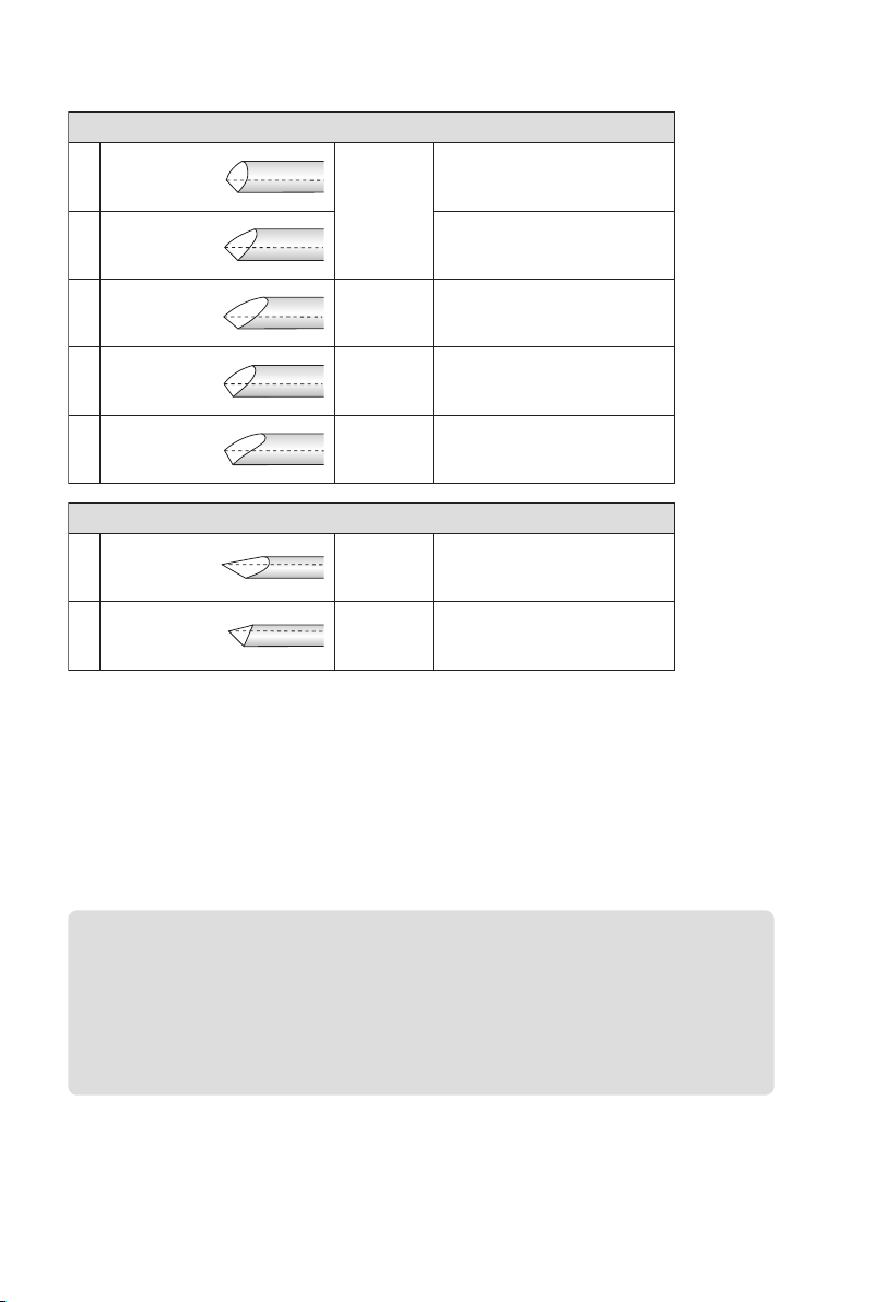
Bowl gouges
1α=45° JS 2
P 65
Hole A
Standard profile.
Only lightly swept back wings.
For turners of all skill levels.
2α=45°
Irish profile. Swept back wings.
Swing the tool 180° from side
to side.
3α=40°
JS 2
P 75
Hole A
With long swept back wings.
Somewhat aggressive.
For professional level turners.
4α=55°
JS 4
P 65
Hole A
The larger edge angle is beneficial
when turning deep bowls.
5α=60°
JS 6
P 75
Hole A
“Ellsworth” shape.
Wings are pronounced convex.
Spindle gouges
1α=30°
JS 2
P 55
Hole B
For tight spots, detail work and
fi nest fi nish.
For professional level turners.
2α=45°
JS 2
P 65
Hole A
Standard profile.
For turners of all skill levels.
Skews
1
Straight edges JS 20°
P 65
Hole B
For tight spots, detail work and
fi nest fi nish.
For professional level turners.
α=30°
2
Straight edges JS 20°
P 55
Hole B
For broad application.
Easier to control than
a 30° edge angle.
α=45°
3
Radius edges JS 30°
P 75
Hole B
For tight spots, detail work and
fi nest fi nish.
For professional level turners.
α=30°
4
Radius edges JS 30°
P 65
Hole B
For broad application.
Easier to control than
a 30° edge angle.
α=45°
Flat
Flat
Flat
Flat
Oval
Oval
Oval
Oval
Selection Chart

79
Shaping
You can do the initial shaping either directly on your Tormek or, if a lot of steel needs to
be removed, on a bench grinder using the Tormek Bench Grinder Mounting Set BGM-100
(page 29).
When shaping on the Tormek, contrary to a high speed bench grinder, you need to apply a
high grinding pressure. Therefore, press with your hand or thumb on the tool to increase the
grinding pressure. Grind one side at the time. This is easier since you do not need to swing
the tool from side to side. Finish the grinding with a full swing over the entire bevel. Do not
spend too long on the same spot on the grindstone, as it will leave grooves on the stone.
Instead, grind on new spots so that you use the whole width of the stone.
By this technique the remaining grooves will not be too pronounced. They will reduce with
future grindings of straight edges. If you immediately require a at surface of the stone, you
can true it with the Truing Tool TT-50.
Check your grinding frequently to ensure that the gouge acquires an even shape. Grind more
on the spots where it is needed. Your hands and eyes decide the nal evenness and shape
of the bevel. Remember that once you have created your desired ngernail shape, this can
be kept forever and you will always benet from the time spent on the initial shaping. This
initial shaping needs only to be made once. It takes 10–20 minutes depending on the original
shape of the tool and on how much steel you need to remove.
Make the first rough shaping on one side at the time. Move the tool sideways so you use the whole
width of the stone and avoid creating grooves.
Grind the other side. Again use the whole width of the stone to wear the stone evenly. Check
frequently to ensure that you are grinding evenly. Grind more where it is needed. Decrease the
grinding pressure as you complete the shape and finish the grinding with a full swing over the
entire bevel.
Grind more here
Both wings now
symmetrical

80
When the desired shape is achieved, check that the protrusion
has not decreased during the shaping. If so, re-position the
tool to the correct protrusion and then make the final shaping.
By doing so, you will ensure that you exactly replicate the edge
geometry at future sharpenings.
Rounding Off the Heel
Some turners round off the heel of the bevel on bowl gouges and spindle gouges. The jig
is designed so that you can move the tool towards the stone and grind the heel. The heel
can be ground either as a at secondary bevel or rounded off by sliding the jig back and
forth during grinding. If you want a more pronounced rounding off, you move the Universal
Support a little towards the grindstone.
You can round off the heel by
moving the stop ring (4) and
thesleeve (2) backwards.
Press the jig towards the grind-
stone so that the stop ring (4) is
in touch with the sleeve (2).
Moving the Universal Support
closer towards the grindstone
gives you a more pronounced
rounding off.
Full swing.Limited swing.
Length of the Wings
The length of the wings depends on how
wide you swing the tool from side to side.
Shape of the Wings
Watch that you grind on the right spots
on the bevel so the wings become sym-
metrical and slightly convex or straight.
They must never be concave. Convex. Concave. Not suitable!
Note You decide how much grinding takes place on any
one spot and hence the final shape. If the wings tend to
be concave, then grind more on the centre of the edge.
81
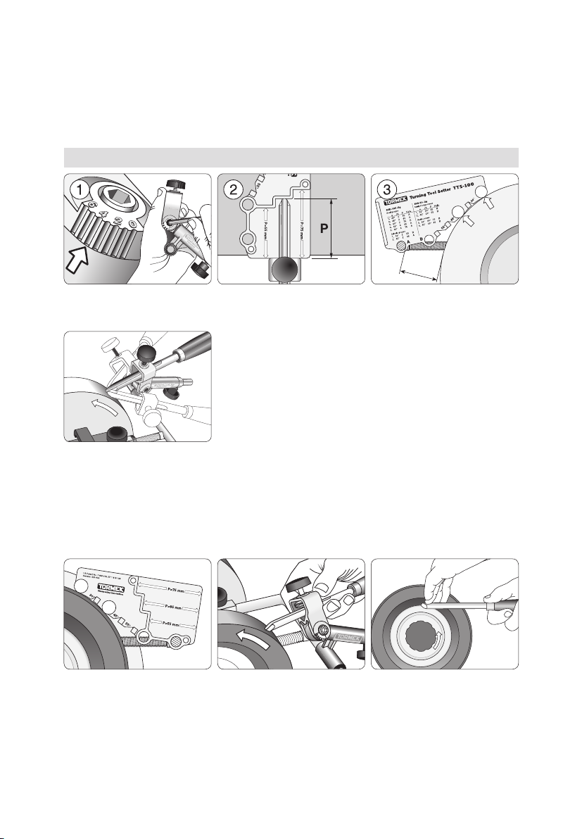
Sharpening
Once you have created the shape of the edge, it is an easy task to quickly re-sharpen the
tool. The sharpening should be done on your Tormek machine for the best nish and to
ensure that the edge is not overheated. Make the three settings noted on the Prole Label
carefully and you will obtain exactly the same shape every time even when the stone wears
and decreases in diameter.
Set the jig, JS. Mount the tool with
afixed protrusion, P.
Set the Universal Support.
Use hole A or hole B.
Sharpen with a light pressure
and swing the tool from side to
side. Since the shape is exactly
replicated and the edge is just
touched up, the sharpening
takes just 20–30 seconds.
Move the Universal Support to
the honing wheel and make the
same setting with the Setter.
Hone by swinging the tool
from side to side. You now
have an extra fine finish.
Polish the flute and remove
theburr on the Profiled Leather
Honing Wheel LA-120.
Honing
Honing and polishing the bevel and the ute to a ner nish will make the sharpness more
durable. Also, use the Setter and jig for this operation and you are sure that you are honing
to exactly the same shape as the sharpening plus you do not risk rounding off the very tip
of the edge.
These three factors determine the geometry of a gouge

82
Other Shapes
You can of course shape your gouge to a different geometry from those provided with the
TTS-100 Setter. This graph shows examples of shapes which you can achieve on a bowl
gouge at various jig settings and edge angles. In each example, the protrusion of the tool in
the jig (P) is 65 mm (2½"). The gouge is swung fully 180º from side to side.
* Geometries achieved with the TTS-100 Setter.
Jig Setting Edge angle
35°
Edge angle
45°
Edge angle
55°
Edge angle
75°
JS 0
JS 1
JS 2
JS 3
JS 4
JS 5
JS 6
*
*

83
Loosen and remove the screw
(8) and the tool holder (1).
Insert the shaft (12) into the
sleeve (2). Note: Position the
sleeve according to the picture!
Mount the screw (8). Lock the
shaft with the Allen key (9)
when tightening.
Turning Cutters
Mounting the jig
Cutters with 5 and 6 mm
(
⁄
"–¼") holes are centered on
the first shoulder on the shaft.
Cutters with 4 mm (
⁄
") holes
are centered bythe M4 screw.
Cutters with 8 mm (
⁄
") holes
are centered on the second
shoulder on the shaft.
Use the Allen key (14), which
comes with the jig.
Mounting the cutter
There are various types and sizes of exchangeable
cutters for hollowing and scraping. The holes vary
from 4–8 mm (⁄–⁄"), but due to a shoulder on the
shaft they can all be mounted with the same screw.
The cutters can be sharpened to their existing shape
or to a new shape.
84
Colour the bevel with a marker. Set the universal support so
thatthe grindstone touches the entire length of the bevel when
rotating it by hand.
At the right setting the stone
removes the colouring along
the whole length of the bevel.
Setting the edge angle
Rotate the jig all the time during the sharpening so you achieve an
even grinding around the whole circumference. Use only a light
pressure for the best result. Slide the jig sideways on the Univer-
sal Support so the grindstone wears evenly.
Smooth the back on the
machined, flat outside of the
grindstone. Move the cutter in
order to use the whole surface
of the stone.
Sharpening
Tip When smoothing the back of the cutter, hold it towards the grindstone
before you start the machine. This is easier and you do not risk dropping it
into the water trough.
If you want an extra fine surface on the bevel, grade the grind-
stone with the Stone Grader SP-650 so it grinds more finely
corresponding to a 1000 grit grindstone.
Important Do not hone these small tools on the leather honing wheel!
They can easily get caught on the leather surface and spoil the leather.

85
Carving Gouges
Carving gouges can be straight, curved or spoon
shaped. They can also be back bent, down bent
or tapered. The jig can be set to compensate for
any radius on the curve so that the grinding takes
place evenly across the edge, so creating a con-
stant edge angle from the centre to the sides of
the gouge.
Unlike turning gouges, carving gouges should not be ground with side bevels. The edge
should form a straight line viewed from above and the corners must be sharp.
The Principle
Use the technique as described in Sharpening Techniques for Carving Gouges and V-tools
on page 20.
Edge Angle
As described in the above chapter on page 24, the choice of edge angle is very important
for a carving gouge. The method of setting the jig for a certain angle depends on whether you
want to replicate an existing edge angle or if you want to put a new edge angle on your tool.
When replicating an existing edge angle, you should use the Marker Method, which is de-
scribed on page 41. If you want to put a new edge angle to your tool, you can either set
the angle by eye or you can use the AngleMaster (page 142).
Shape the edge by resting the
tool on the Universal Support
placed horizontally and close to
the stone.
The edge plane angle (γ) should
be approx. 20° (page 21).
Flatten and smooth the blunted
edge with the fine side of the
Tormek Stone Grader, SP-650.
Shaping the edge
86
Now you have a line of light,
which is your guide as to where
to grind.
When cutting steep bowls using
a curved or a down bent gouge,
the edge plane angle can be
decreased. Here it is 0°.
Line of light
Mount the gouge in the jig
protruding approx. 100 mm (4").
The stop ring (4) must be locked
close to the sleeve (2).
Put the jig on the Universal
Support and swing it to one
side. Set the jig so that the
plane of the edge is approx.
parallel to the axis of the stone.
The edge angle will now be
equal across the edge. If the
thickness of the steel is even,
the bevel length will also be
equal along the edge.
Setting the jig
If the shank has a convex upper
side, you should grind it flat to
make sure that the tool does
not turn in the jig.
Set the edge angle by adjust-
ing the Universal Support. When
replicating an existing angle, use
the Marker Method. When setting
a new angle you can use the
AngleMaster.
Setting the edge angle
87
Always grind where the line of
light is the thickest while swing-
ing the tool.
Check frequently where the
grinding takes place. Grind until
you get an even and thin line
of light.
Grade the grindstone for fine
sharpening with the fine side
ofthe Stone Grader SP-650.
Grinding
Line of light
Continue sharpening.
Check the result frequently.
Remove the burr on the leather honing wheels to observe the
lineof light more clearly. The tool is left mounted in the jig.
Sharpen again. Now with a
very light pressure. Check
frequently so that you do not
over-sharpen.
Stop sharpening immedi-
ately when the line of light
disappears, which is a sure
sign that the edge is sharp.
Be careful so you do not
roundoff the corners.
Woodcarving tools should
havesharpcorners!
Important It is very easy to be misled by the burr and mistake the burr for
the line of light! Therefore you must remove the burr frequently during the
finishing of the grinding operation, so you clearly can watch the progress ofa
gradually thinner the line of light.

88
It is very easy to over-sharpen the
edge at the end of the sharpen-
ing. If this happens, you need to
reshape the edge and start again
from the beginning.
Keep the tool in the jig and
honeand polish the inside on
the Profiled Leather Honing
Wheel LA-120.
Hone and polish the bevel. Set the Universal Support so that the
honing angle is the same as the grinding angle. Use the Marker
Method. Hone away the burr and polish the bevel to a mirror
finish.
Honing
Leave the tool in the jig and
test the sharpness by pushing
the edge across the fibres in a
piece of wood. The edge should
cut easily and leave a smooth
surface without tearingthe
fibres.
If the edge needs further honing or sharpening on some spots,
you can continue with the same setting. When you are satis-
fied with the result, you remove the tool from the jig after having
measured and noted the protrusion (P) and the jig setting.
Please see the next page.
Testing the sharpness
89
Documentation of the Shape
The shape of the gouge is determined by the jig setting (JS) and the protrusion (P). Note
these settings on the prole label, which comes with the jig. Now you can exactly replicate
this shape at future re-sharpenings. Set the edge angle with the Marker Method or the Spacer
Block Method.
Note the jig setting (JS) and the protrusion (P) on the label.
Usethe water proof pen which comes with the jig.
Attach the label to the ferrule
and you are assured that you
have the same settings at future
sharpenings.
A back bent gouge is ground
with the jig setting 0.
You can also grind a down bent
gouge. The jig is set as shown
on page 86.
Back Bent and Down Bent Gouges

90
V-tools
These tools are considered the most difcult to
grind. The reason is that it has two edges joined
with a radius.
However, with the method described here, you
will also manage to achieve a sharp and correctly
shaped edge on these tools.
The principle is the same as for carving gouges,
i.e. you rst give the tool its right shape and then
let the line of light guide you as to where to grind.
The Principle
Use the technique as described in Sharpening Techniques for Carving Gouges and V-tools
(page 20).
Edge Angle
As described in the chapter above on page 24, the choice of edge angle is very important
for a carving gouge. The method of setting the jig for a certain angle depends on whether you
want to replicate an existing edge angle or if you want to put a new edge angle on your tool.
Shape the edge. Rest the tool
on the Universal Support posi-
tioned horizontally.
The edge plane angle (γ) should
be approx. 20° (page 21).
Flatten and smooth the blunt
edge with the fine side of the
Tormek Stone Grader, SP-650.
Shaping the edge
The blunt edge appears as
a line of light, which is your
guide as to where to grind.
Line of light

91
Mount the tool in the jig pro-
truding approx. 100 mm (4").
The stop ring (4) must be locked
close to the sleeve (2).
Turn the jig so one wing lies flat
on the grindstone. Set the jig so
that the edge is approximately
parallel to the axis of the stone.
Now the jig is set to suit the
shape of the tool, the edge
angle will be uniform.
Setting the jig
Setting the edge angle
Control the grinding pressure with your thumb and control where the grinding takes place by gently
turning the tool with your hand. Check frequently where the grinding is taking place. Only grind
where the line of light is the thickest. Do not slide the tool sideways. Keep it on the same spot on
the grindstone for the best control. Rest your hands on the Universal Support all the time and you
get a good control.
Grinding
Set the edge angle by adjusting
the Universal Support. When
replicating an existing angle,
use the Marker Method. When
setting a new angle you can
use the AngleMaster.

92
Grind until you get an even and
thin line of light.
Now grind the other wing in the
same way.
Then grind the keel. Turn
the tool from side to side to
equalise the grinding towards
the wings.
Grade the grindstone for fine
sharpening with the fine side
ofthe Stone Grader SP-650.
Continue sharpening one wing
at a time and then the keel.
Check the results frequently.
Remove the burr on the leather
honing wheels so that you can
better observe the line of light.
Now sharpen again with a
very light pressure. Check
frequently so that you do not
over-sharpen.
Stop sharpening immediately
when the line of light disap-
pears, which is a sign that the
edge is sharp.
Important It is very easy to be misled by the burr and mistake the burr for
the line of light! Therefore you must remove the burr frequently during the
finishing of the grinding operation, so you clearly can watch the progress of a
gradually thinning line of light.

93
Keep the tool in the jig and
hone and polish the inside on
the Profiled Leather Honing
wheel LA-120.
Hone and polish the bevels. Set the Universal Support so that the
honing angle is the same as the grinding angle. Use the Marker
Method. Hone away the burr and polish the bevels to a mirror
finish.
Honing
It is easy to over-grind the edge
at the end of the grinding. If this
happens, you need to reshape
the edge and start again from
the beginning.
This is now how the tool should
appear. The keel is slightly
longer than the bevel of the
wings since the steel is thicker
in the centre.
The tool cuts more easily if you
round the keel. Move the Uni-
versal Support slightly towards
the grindstone and grind gently
while swinging the tool from
side to side.
Keep the tool in the jig and test the sharpness by pushing the
edge across the fibres in a piece of wood. The edge should cut
easily and leave a smooth surface without tearing the fibres. If
the edge needs further honing, you can continue with the same
setting. When you are satisfied with the result, you remove the
tool from the jig.
Testing the sharpness

94
If the steel thickness varies, the length of the bevel will also vary
despite the fact that the edge angle is the same. This has no
influence on the function of the tool, as it depends on the edge
angle. A V-tool with an even steel thickness has the same bevel
length on the whole wing.
Uneven thickness of the steel
Uneven thickness Even thickness
Other tormek Power Tools manuals


Popular Power Tools manuals by other brands


Campbell Hausfeld
Campbell Hausfeld DG460500CK Operating instructions and parts manual

Central Machinery
Central Machinery 59766 Owner's manual & safety instructions

molex
molex TM42 Operation manual

Planmeca
Planmeca PlanMill 40 S quick start guide

Milwaukee
Milwaukee M12 DE Original instructions

Hainbuch
Hainbuch vario flex operating instructions


