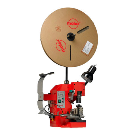
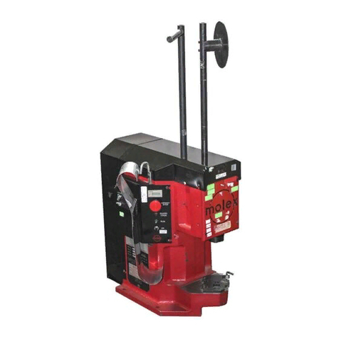
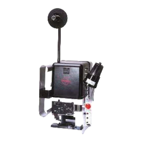
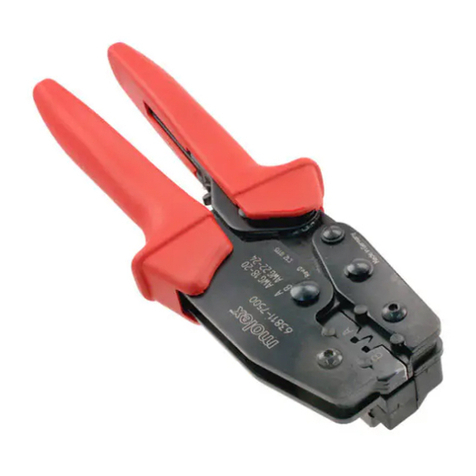
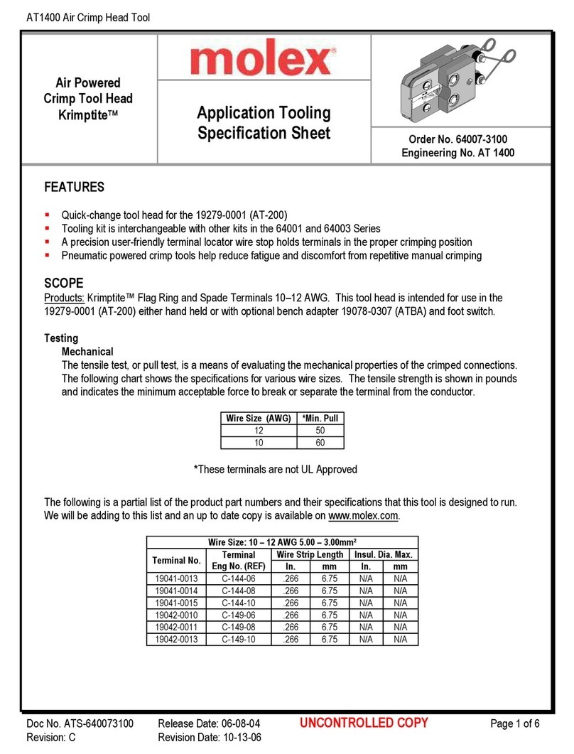
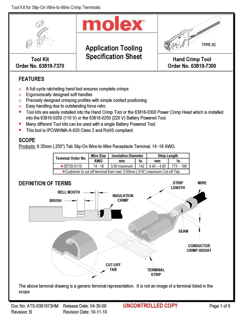
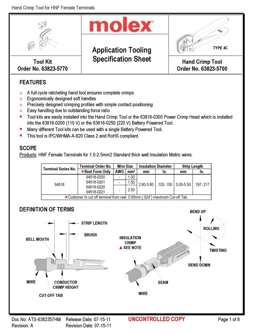
molex TM42 User manual

Chipsmall Limited consists of a professional team with an average of over 10 year of expertise in the distribution
of electronic components. Based in Hongkong, we have already established firm and mutual-benefit business
relationships with customers from,Europe,America and south Asia,supplying obsolete and hard-to-find components
to meet their specific needs.
With the principle of “Quality Parts,Customers Priority,Honest Operation,and Considerate Service”,our business
mainly focus on the distribution of electronic components. Line cards we deal with include
Microchip,ALPS,ROHM,Xilinx,Pulse,ON,Everlight and Freescale. Main products comprise
IC,Modules,Potentiometer,IC Socket,Relay,Connector.Our parts cover such applications as commercial,industrial,
and automotives areas.
We are looking forward to setting up business relationship with you and hope to provide you with the best service
and solution. Let us make a better world for our industry!
Contact us
Tel: +86-755-8981 8866 Fax: +86-755-8427 6832
Email & Skype: [email protected]om Web: www.chipsmall.com
Address: A1208, Overseas Decoration Building, #122 Zhenhua RD., Futian, Shenzhen, China

TM42 Termination Press
Order No: TM-690025099 Release Date: 08-08-02 UNCONTROLLED COPY Page 1 of 49
Re ision: H Re ision Date: 01-15-13
Tm42 Termination Press
Use with Molex T2, and all Terminator Dies
Operation Man al
Order No.69002-5099
% Description
% Operation
% Maintenance

TM42 Termination Press
Order No: TM-690025099 Release Date: 08-08-02 UNCONTROLLED COPY Page 2 of 49
Re ision: H Re ision Date: 01-15-13
Safety Warnings and Information
Read
and
nderstand
all of the instructio
ns and safety information in this manual before
operating or ser icing this tool.
Keep this manual a ailable when using this tool.
Replacement manuals are a ailable for download at no charge at www.molex.com.
SAFETY ALERT SYMBOL
This symbol is used to call your attention to hazards or unsafe practices which could result in an injury
or property damage. The signal word, defined below, indicates the se erity of the hazard. The message
after the signal word pro ides information for pre enting or a oiding the hazard.
DANGER
DANGER:
Indicates an imminently hazardous situation which, if not a oided, could result in death or serious injury.
WARNING
WARNING:
Indicates a potentially hazardous situation which, if not a oided, could result in death or serious injury.
CAUTION
CAUTION:
Indicates a potentially hazardous situation which, if not a oided, may result in minor or moderate injury.
CAUTION may also be used to alert against unsafe practices associated with e ents that could lead
to personal injury.
WARNING
WARNING
Always wear proper eye protection when
Operating or ser icing this equipment.
Failure to wear eye protection could result
in serious eye injury from flying debris.
Heavy Object
To a oid muscle strain or back injury, use lifting
aids and proper lifting techniques when remo ing
or replacing.
Failure to obser e these precautions may result in
injury or property damage.
WARNING
WARNING
Never wear clothing or jewelery that is loose or
That could potentially hang into the equipement
and get caught.
Failure to obser e this warning could result in
Se ere Injury or death.
Never
install or ser ice this machine while
connected to any electrical power source.
Disconnect power by unplugging the press
from its power source.
Failure to obser e this warning could result
In se ere injury or death.
WARNING
WARNING
Never
operate, ser ice, install, or adjust this
machine without proper instruction and without
first reading and understanding the instructions
in this manual and all applicable press and/or
wire processing machine.
manuals.
Always hand cycle the applicator in the equipment
to ensure the tooling is properly aligned.
Failure to obser e these precautions may result in
Injury or property damage.

TM42 Termination Press
Order No: TM-690025099 Release Date: 08-08-02 UNCONTROLLED COPY Page 3 of 49
Re ision: H Re ision Date: 01-15-13
WARNING
WARNING
Never use this press or wire processing machine
without guards or safety de ices that are intended
to pre ent hands from remaining in the die space.
Failure to obser e this warning could result in
Se ere injury or death.
Do not se
compressed air to
clean
this equipment.
The forces created by compressed
air can force debris into the tool.
Failure to obser e these precautions may
result in injury or property damage.
WARNING
Always wear proper ear protection when Operating or ser icing this applicator.
CAUTION
NEVER
install or remo e terminator dies with the flywheel in motion or the motor running.
Never install or remo e terminator dies or ser ice this machine without manually cycling the press to erify that the clutch control
collar is in the locked position (past top dead center) block the press ram in the full up position if a defecti e clutch is suspected.
Ca tion the TM42 press is shipped from the factory for operation with US standard tooling. When using European Standard tooling,
the spacer shim (69002-5560) supplied with the unit must be added between the bolster plate and the press frame
Failure to remo e this shim before installing US standard tooling may result in se ere damage to the tooling and/or press.
CAUTION
Never
perform a
ny ser ice or maintenance other than as described in this manual.
Never modify, alter or misuse the equipment
Molex crimp specifications are alid only when used with Molex terminals, applicators and tooling.
Failure to obser e this precaution may result in injury and property damage.
Tooling Technical Assistance
Molex offers tooling technical assistance for customers who may need some guidance for tooling adjustments. This support can
be obtained by calling either of the two numbers listed below and asking for the Molex Tooling Group.
Call Toll Free 1-800-786-6539 (US) 1-630-969-4550 (Global).
This assistance is limited to the operation and set-up of a customer’s Molex Press. Questions with regard to Molex connector
products or how to identify the proper tooling and/ or tooling documentation should be directed to your local Molex personnel or
Customer Ser ice Representati e.
When calling for ser ice on the press a copy of the Tooling Manual and Specific Applicator Tooling Specification Sheet should be
present and a person that is familiar with the applicator should be present. Be sure the following information is supplied:
1. Customer name
2. Customer address
3. Person to contact such as (name, title, e-mail, and telephone number
4. Applicator order number (Lease number also if applicable)
5. Serial number (Lease number also if applicable)
6. Molex Connector product order number
7. Urgency of request
8. Nature of problem
Molex Application Tooling Gro p
2200 Wellington Court
Lisle, IL 60532, USA
Tel: +1 (630) 969-4550
Fax:+1 (630) 505-0049
Visit our Web site at http://www.molex.com

TM42 Termination Press
Order No: TM-690025099 Release Date: 08-08-02 UNCONTROLLED COPY Page 4 of 49
Re ision: H Re ision Date: 01-15-13
Table of Contents
Contents
Tm42 Termination Press ............................................................................................................................................... 1
Order No.69002-5099 .................................................................................................................................................... 1
Safety Warnings and Information .................................................................................................................................. 2
Table of Contents .......................................................................................................................................................... 4
Section 1 ................................................................................................................................................................... 6
General Description .............................................................................................................................................. 6
1.1 Description................................................................................................................................................. 7
1.2 Features .................................................................................................................................................... 7
1.3 Technical Specifications ............................................................................................................................ 7
1.4 Deli ery Check .......................................................................................................................................... 7
1.5 Tools .......................................................................................................................................................... 8
Section 2 ................................................................................................................................................................... 9
Installation............................................................................................................................................................. 9
2.1 Lifting/Mounting ....................................................................................................................................... 10
2.2 Reel Support Assembly ........................................................................................................................... 11
2.3 Foot Pedal and Power Connection .......................................................................................................... 11
2.4 Hand Rest................................................................................................................................................ 11
2.5 Safety and Work Area Check .................................................................................................................. 11
2.6 Bolster Shim Installation and Remo al .................................................................................................... 12
Section 3 ................................................................................................................................................................. 14
Setup and Operation ........................................................................................................................................... 14
3.1 Termination Die Set Installation and Remo al ......................................................................................... 15
3.2 Loading the Terminal Strip....................................................................................................................... 16
3.3 Punch and An il Alignment ...................................................................................................................... 18
3.4 Feed Finger Adjustment .......................................................................................................................... 18
3.5 Forward Feed Adjustment ....................................................................................................................... 18
3.6 Back Stroke Feed Adjustment ................................................................................................................. 19
3.7 Manually Cycling the Press ..................................................................................................................... 19
3.8 Conductor Crimp Punch Adjustment ....................................................................................................... 20
3.9 Insulation Crimp Punch Adjustment ......................................................................................................... 20
3.10 Operation ................................................................................................................................................. 21
Section 4 ................................................................................................................................................................. 22
Maintenance and Clutch Unit Ser ice ................................................................................................................. 22
4.1 Cleaning .................................................................................................................................................. 23
4.2 Lubrication ............................................................................................................................................... 23
4.3 Perishable Orders .................................................................................................................................... 24
4.4 Spare Orders ........................................................................................................................................... 24
4.5 Clutch Unit Ser ice Adjust/Repair ............................................................................................................ 24
4.6 Oiler ......................................................................................................................................................... 27
Section 5 ................................................................................................................................................................. 29
5.1 Parts List ................................................................................................................................................. 30
5.2 Assembly Drawings ................................................................................................................................. 33
5.3 Electrcal Parts List ................................................................................................................................... 37
5.3 Electrcal Schematic ................................................................................................................................. 38
5.4 Troubleshooting ....................................................................................................................................... 39
Appendix A .............................................................................................................................................................. 41
A.1 Conductor Brush and Terminal Position .................................................................................................. 42
TM42 Termination Press
Order No: TM-690025099 Release Date: 08-08-02 UNCONTROLLED COPY Page 5 of 49
Re ision: H Re ision Date: 01-15-13
A.2 Conductor Bell Mouth and Terminal Cutoff Tab ....................................................................................... 43
A.3 Crimp Height Measurement .......................................................................................................................... 44
A.4 Insulation Crimp ....................................................................................................................................... 44
A.5 Pull Force Testing .................................................................................................................................... 46
Appendix B .............................................................................................................................................................. 48
EC Declaration of Conformity ............................................................................................................................. 49

TM42 Termination Press
Order No: TM-690025099 Release Date: 08-08-02 UNCONTROLLED COPY Page 6 of 49
Re ision: H Re ision Date: 01-15-13
Section 1
General Description
1.1 Description
1.2 Features
1.3 Technical Specifications
1.4 Deli ery Check
1.5 Tools

TM42 Termination Press
Order No: TM-690025099 Release Date: 08-08-02 UNCONTROLLED COPY Page 7 of 49
Re ision: H Re ision Date: 01-15-13
General Description
1.1 Description
The 69002-5000 (240V AC Version) and the 69002-
5001(120V AC Version) TM42 Termination Machine is
an electrically operated, single-cycle, flywheel press.
It is designed to pro ide an effecti e method of
terminating a wide range of Molex side-feed crimp
terminals to pre-stripped discrete wire and cable.
Production flexibility is obtained through the use of
interchangeable modular terminator dies. These dies
are inexpensi e because, unlike a modular applicator,
all crimp height and terminal feed adjustments are
located in the press. The TM42 is ideally suited for
mid- olume, semi-automatic operation.
The TM42 will complete one crimping cycle with each
depression of the foot pedal. Safe operation is
pro ided by an interlock switch that renders the press
inoperati e if the safety guard is remo ed.
1.2 Feat res
% Utilizes Molex TM40, TM42, T2, and FFC
Terminator Dies.
% Independent conductor and insulation adjustments
with position reference indicators.
% Bench-mounted unit requires electrical power
only. Meets OSHA safety and noise standards.
European CE rated.
% Quick-release tooling for fast and simple
changeo er. Ability to remo e upper crimp tooling
without remo ing lower die.
% Ideal for mid- olume and semi-automatic
applications.
% 38.1 mm Stroke, No ram adjustment required.
% Meets ISO Standards.
% Flexible external work light.
% Uni ersal feed adjustment to accept Molex side-
feed terminals.
% Totally enclosed for operator safety, including a
power interlock switch for the front guard with
“GUARD OPEN” indicator light.
% Resettable counter for accurate batch-counting.
% Modular solid-state controls. Power cord and foot
pedal plug in easily.
1.3 Technical Specifications
Dimensions with reel mo nted
Width: 540.00mm (21.30”)
Depth: 330.00mm (13.00”)
Height: 1,150.00mm (45.00”)
(Witho t reel mo nted)
Width: 330.00mm (13.00”)
Depth: 330.00mm (13.00”)
Height: 914.00mm (36.00”)
Weight
100kg (220 lbs.) Unpacked
110kg (242 lbs.) Gross
Power Req irements
69002-5001 120V AC, 1Ph, 60 Hz, 5.8/2.9 Amp
Note: Press shipped setup for 120V ser ice.
69002-5000 240V AC, 1Ph, 50 Hz, 3.8 Amp
European CE Rated.
Prod ction Rate
Depending on the operator skill and the wire
length, 2500 terminations per hour maximum.
Flywheel rotation: 210 RPM.
Processing Capability
Up to 4.0mm² of copper conductor in solid or
stranded wire.
So nd Level
Operator will be exposed to less than 85 DB.
1.4 Delivery Check
After remo ing the packaging band, the top and
sides of the box should lift off easily. Make sure
the following items are included in this package.
Description Qty
Main press body 1
Reel support assembly 1

TM42 Termination Press
Order No: TM-690025099 Release Date: 08-08-02 UNCONTROLLED COPY Page 8 of 49
Re ision: H Re ision Date: 01-15-13
Two cartons are included that contain the
following;
Carton 1
69002-5715 Foot switch assembly 1
Carton 2
Power cord 1
69018-6237 (for 69002-5001)
OR
62500-0113 (for 69002-5000)
69002-5547 Hand rest 1
TM-690025099 TM42 Operation Manual 1
69002-5560 Shim 1
69001-0106 Feed finger crank 1
69018-8235 10mm hex wrench 1
* For International applications, the power cord/plug
may need to be replaced or adapted with the
appropriate connection.
1.5 Tools
The following tools may be needed for setup and
adjustment of the TM42 press and terminator die.
Ε
ΕΕ
Ε Metric hex wrench set
Ε
ΕΕ
Ε English hex wrench set (for older terminator die
set designs)
Ε
ΕΕ
Ε Large and small standard screwdri er
Ε
ΕΕ
Ε Adjustable wrench
Ε
ΕΕ
Ε Needle nose pliers
Ε
ΕΕ
Ε Crimp micrometer
Ε
ΕΕ
Ε Eye loupe (10x)
Ε
ΕΕ
Ε Wire stripper/cuter

TM42 Termination Press
Order No: TM-690025099 Release Date: 08-08-02 UNCONTROLLED COPY Page 9 of 49
Re ision: H Re ision Date: 01-15-13
Section 2
Installation
2.1 Lifting/Mounting
2.2 Reel Support
2.3 Foot Pedal and Power Connection
2.4 Hand Rest
2.5 Safety and Work Area Check
2.6 Bolster Shim Installation and Remo al

TM42 Termination Press
Order No: TM-690025099 Release Date: 08-08-02 UNCONTROLLED COPY Page 10 of 49
Re ision: H Re ision Date: 01-15-13
WORK BENCH
TERMINAL GUIDE
ASSEMBLY (INSTALLED)
REEL SUPPORT
ASSEMBLY
MAIN PRESS BODY
LIFTING HOOKS
PRESS CONTRO
L
ASSEMBLY
POWER CORD
FOOT PEDAL CORD
HAND REST
FOOT PEDAL
ASSEMBLY
Fig re 2-1
CAUTION: To a oid serious injury support the ram in the upper position with a hardwood wedge (approximately 1 7/8”
high).
When changing tooling or working on the clutch, a block
should be inserted under the ram (See Illustration). This
also pertains when the guards are taken off. The block
supports the ram and the tooling, if block is not inserted the
Ram can fall suddenly and cause serious injury.
When procedure is complete be sure to remo e the block
prior to cycling the Press.
2.1 Lifting/Mo nting
WARNING: The TM42 press weighs o er 100 kg. (220
lbs.) and is NOT intended to be lifted by an indi idual. The
guarding is not attached to pro ide support for lifting
purposes. Mechanical lifting de ices should be used. A person lifting the press can sustain se ere back or other
injuries.
Lifting hooks are pro ided on each side of the press. See Figure 2-1. A hea y-duty chain, rope, cable, or belt can be
used with loops, links, or rings on each end that can securely attach to the lifting hooks. An electric, hydraulic, or
mechanical crane should be used to lift the press. Lift the press up approximately 12.0mm (0.50”) and erify that the
press is well balanced. Upon erification, the press can be lifted onto a sturdy workbench. Access to the back of the
machine is required for manual cycling. A minimum 25.00mm (1.00”) thick wooden bench top will offer quiet ibration-
PLACE BLOCK
HERE
(WITH PRESS
RAM IN
THE UP
POSTION)

TM42 Termination Press
Order No: TM-690025099 Release Date: 08-08-02 UNCONTROLLED COPY Page 11 of 49
Re ision: H Re ision Date: 01-15-13
“GUARD OPEN”
INDICATOR
LIGHT
Fig re 2
-
3
RUN “ON”
BUTTON
“RUN”
INDICATOR
LIGHT
“E
-
STOP”
BUTTON
free operation. TM42 should be attached to the table with
(2) 12.0mm bolts and washers. For marking the tabletop
(See Figure 2-2), or use the remo able template at the
back of the manual. Drill the clearance holes for the
12.0mm bolts and secure the press to the table. Bolts are
not supplied by Molex.
2.2 Reel S pport Assembly
Install the reel support assembly by inserting the support
tube in the hole located on the left side of the top co er.
2.3 Foot Pedal and Power Connection
1. Connect the 4-pin plug for the foot pedal in the rear of
the press control assembly.
2. Turn the Locking Ring clockwise until tight.
3. Connect the power cord plug to the socket in the back
of the control assembly. Use a grounded electrical outlet as the power source.
4. Two fuses are located in the fuse drawer directly abo e the power socket. To replace the fuses, use a small
screwdri er to open the fuse drawer, remo e damaged fuses and replace.
2.4 Hand Rest
Attach the hand rest with one M6 x 10.0mm BHCS located at the front center of the press.
See Figure 2-1.
2.5 Safety and Work Area Check
1. Check that the work area is well lighted. Adjust the work
light for best isibility.
2. Check that the work area is clean and free of debris.
3. Check that no tools ha e been left in the machine or
work area.
Ne er operate in areas of excess moisture or water.
Check that all safety guards are in place. NEVER
operate this press without press guards in place. The
guard indicator light is located on the front of the press
control assembly. See Figure 2-3.
4. Check that the crimping position is ergonomic for the
operator’s size. A bench height of 762.00 to 813.00mm
(30.00 to 32.00”) will pro ide operator comfort, and
allows both feet to rest on the floor. The foot pedal
should be placed in a comfortable position.
5. Check that the press position is located approximately 150.00mm (6 .00“) from the edge of the bench. A chair or
stool with adjustable height and backrest should be pro ided for maximum comfort and back support for the
operator. Obser e where the emergency stop button is on the control panel. See Figure 2-3.
Fig re 2
–
2
Table Top Mo nting Pattern
15.9mm
(.625”) DIA. (4)
212.73mm
(8.38”)
0
76.96mm
(3.03”)
155.58mm
6.12”)
28.58mm
(1.12”)
25.4mm (1.0”) DIA. OR
SQUARE HOLE FOR
SCRAP
76.2mm
(3.0”)
0
FRONT OF PRESS

TM42 Termination Press
Order No: TM-690025099 Release Date: 08-08-02 UNCONTROLLED COPY Page 12 of 49
Re ision: H Re ision Date: 01-15-13
Fig re 2
-
4
(1) ON EACH SIDE
REQUIRES LOOSENING ONLY
690025560
(.50mm SHIM)
M6 X 25LG BHCS
M10 X 16LG
SHCS (2)
M10 X 16LG
BHCS (4)
LIFTING
SLOTS (2)
69025506
(BOLSTER PLATE)
638004205
(.25mm SHIM)
GUARD
PUSH ROD
M6 JAM NUT
“E
-
STOP”
BUTTON
CAUTION: Molex recommends that the operator and obser ers wear eye protection when the press is in
operation or being ser iced.
2.6 Bolster Shim Installation and Removal
CAUTION: Before installing any tooling in this press, determine the presence or absence of the .50mm (.020”) shim.
This shim is in addition to the .25 mm (.010”) that should always be present. The TM42 is shipped from the factory for
operation with U.S. designed terminator dies (order numbers 11-40-2XXX, 6384X-XXXX, or 6385X-XXXX.
When using European designed tooling (order number 69001-XXXX), an additional .50mm (.020”) Shim (P.N. 69002-
5560), supplied with the unit must be added between the bolster plate and the press frame to set the shut height. Do
not remo e the .25.00mm (.010”) shim.
WARNING: Failure to install the shim 69002-5560 for European tooling may result in a nonfunctional terminator die
set. Failure to remo e the .50mm (.020”) shim before installing U.S. terminator dies may result in damage to the
tooling and/or press.

TM42 Termination Press
Order No: TM-690025099 Release Date: 08-08-02 UNCONTROLLED COPY Page 13 of 49
Re ision: H Re ision Date: 01-15-13
Refer to Section 3 for setup, manual cycling, and operation before attempting any crimp terminations under power. If
the press is running, push the emergency stop button located on the front of the press control assembly. The motor
and flywheel will stop. The work light will still operate.
1. Remo e the press guards by remo ing the (2) M10 BHCS (See Figure 2-4) located on the front bolster plate,
and loosen (1) on each side. Once remo ed, the guard interlock switch will disconnect power to both the motor
and clutch.
2. Remo e the push rod from the hole on the right side of the bolster plate. If necessary, remo e any tooling, and
then remo e (2) M10 SHCS attaching the bolster plate to the press frame.
3. Lift the bolster plate away from the locating dowels by placing a screwdri er in the (2) lifting slots on the underside
of the bolster plate. Remo e or install the .50mm (.020”) spacer and erify the presence of the .250mm (.010”)
spacer.
4. Position the bolster plate on the locating dowels and refasten with the (2) M10 SHCS. Replace the push rod.
Follow the tooling setup procedures in Section 3.
CAUTION: Always manually cycle the press before restoring power to the machine.

TM42 Termination Press
Order No: TM-690025099 Release Date: 08-08-02 UNCONTROLLED COPY Page 14 of 49
Re ision: H Re ision Date: 01-15-13
Section 3
Set p and Operation
3.1 Termination Die Set Installation and Remo al
3.2 Loading the Terminal Strip
3.3 Punch and An il Alignment
3.4 Feed Finger Adjustment
3.5 Forward Feed Adjustment
3.6 Back Stroke Adjustment
3.7 Manually Cycling Press
3.8 Conductor Crimp Punch Adjustment
3.9 Insulation Crimp Punch Adjustment
3.10 Operation

TM42 Termination Press
Order No: TM-690025099 Release Date: 08-08-02 UNCONTROLLED COPY Page 15 of 49
Re ision: H Re ision Date: 01-15-13
Fig re 3–1 TM42 PRESS AND TERMINATION DIE
SCRAP CHUTE
ANVILS
WIRE STOP
REAR STRIKER
CONDUCTOR
PUNCH
CENTER CARRIER
CUT-OFF
NOSE HOLDDOWN
RIGHT
LOCATING PLATE
BOLSTER
PLATE
PUNCH
RELEASE PIN
INSULATION
PUNCH
FRONT STRIKER
COVERS
PUNCH PLATE
DRAG
PLATE
TRACK
FRONT CUT
-
OFF
TOOLING
LEFT LOCATING PLATE
3.1 Termination Die Set Installation and Removal
Always turn off and disconnect the power supply to the press. Power down the press by pressing the emergency
stop button located on the front of the control panel.
Termination Die Removal
1. Remo e the press guards by remo ing the (2) M10 BHCS (See Figure 1-4) located on the front bolster plate, and
loosen (1) on each side.
NOTE: Once remo ed, the guard interlock switch will disconnect power to both the motor and clutch. The work light
will still operate if the unit is still connected to the power source.
2. Set both the conductor and insulation indicators to a reference setting of “1”. See Figure 3-3.
3. Loosen the M5 BHCS and remo e the right locating plate.
4. Lift the feed finger clear and slide the terminator die out of the press.
5. Remo e the punches, nose hold-down, rear striker, and center carrier cutoff tooling.
6. The terminator die is best stored in its original container.

TM42 Termination Press
Order No: TM-690025099 Release Date: 08-08-02 UNCONTROLLED COPY Page 16 of 49
Re ision: H Re ision Date: 01-15-13
Termination Die Installation
Before any die is installed make sure the co er
alignment procedure and the track adjustment
procedure, (when applicable) ha e been completed. See
the appropriate terminator die instruction manual for
these procedures.
1. Power down the press and remo e the guards as
described in Section 3.1.1, steps 1 and 2.
2. Not all terminator dies ha e contact nose hold down,
rear strikers, or center carrier cutoff tooling. If
present on the terminator die, attachment points are
located behind the punches either in the front of or
on the bottom of the ram See Figure 3-1. Refer to
the assembly drawing supplied with each indi idual terminator die for parts supplied with that terminator.
3. Fit the (2) punches in the opening on the underside of the ram. The conductor punch should be positioned in the
rear See Figure 3-1. A click will be heard when
the punch retaining/release pin engages.
4. Set both the conductor and insulation indicators to
a reference setting of “1”. See Figure 3-3.
5. The front striker slides in front of the punches and
is attached with a screw through the hole in the
punch plate.
6. Make sure the bolster plate is clean and free of
debris.
7. Lift the feed finger clear and slide the terminator
die onto the left locating plate.
8. Attach the right locating plate and tighten the M5
BHCS.
3.2 Loading the Terminal Strip
CAUTION: The specified terminal is printed on the
setup sheet supplied with the terminator die. Do not
use any terminal not indicated on that setup sheet.
1. Power down the press and remo e the guards as described in Section 3.1.1, steps 1 and 2.
2. Remo e the pull pin and outer hub on the press reel support.
3. Remo e all tape on the edge of the reel.
4. Place the terminal reel on the exposed shaft so the terminal strip comes off the reel in proper orientation.
5. Place the outer hub back on the shaft and lock in position so there is enough tension so that the reel does not freely
rotate and unwind the terminals. The tension should be loose enough that a light pull on the terminals will rotate the
reel.
6. Place the pull pin back on the end the shaft. This will pre ent the hub from falling off should the hub locking screw
become loose.
7. Unwind the terminal strip under the terminal guide. See Figure 3-4. Be careful not to distort the terminals or the
strip while feeding the terminals into the terminator die.
Fig re 3-2 GUARD REMOVAL
GUARD
M6 X 25 LG BHCS
PUSH ROD
M6 HEX NUT
(THIN)
M10 X 16LG
BHCS (4)
Fig re 3
-
3 HEIGHT SETTING
SETTING 1 IS MAXIMUM HEIGHT
SETTING 6 IS MINIMUM HEIGHT
INSULATION
ADJUSTMENT
INDICATOR
CONDUCTOR
ADJUSTMENT
INDICATOR
INSULATION
ADJUSTMENT CAM
CONDUCTOR
ADJUSTMENT LOCK
CONDUCTOR
ADJUSTMENT
PUNCH
RELEASE PIN
FACE PLATE

TM42 Termination Press
Order No: TM-690025099 Release Date: 08-08-02 UNCONTROLLED COPY Page 17 of 49
Re ision: H Re ision Date: 01-15-13
Fig re 3
–
4 REEL INSTALLATION
CORRECT
TERMINAL FEED
TERMINAL
GUIDE
OUTER HUB
PULL PIN
REEL
HUB
LOCKING
SCREW
8. Most terminator dies do not ha e any track adjustment features.
For this type, lift both the drag and anti-back-up pins located on
the front of the terminator die. This will allow the terminals to
slide freely through the terminator die track. See Figure 3-5.
9. For track adjustment type terminator dies rotate the drag cam
until the drag frame is fully raised. See Figure 3-6. This will
allow the terminal to slide freely through the terminator die
track.
10. Load the terminal strip under the rear co er plate until the first terminal comes to rest centered abo e the an il.
See Figure 3-7.
11. Release the terminal drag and anti-backup pins for non-adjustment terminators, or rotate the drag cam to engage
the terminal drag frame on the track adjustment style dies.
CAUTION: Terminals and terminal carrier strips may ha e sharp edges that can scratch or cut. Use caution while
handling terminals.
12. To remo e the terminal strip, raise the terminal drag and/or anti-back-up finger. Lift the feed finger and pull the
terminal carrier strip back using needle nose pliers until disengaged from the terminator track. If preferred, cut the
terminal carrier strip and pull it through the terminator die.
Fig re 3-6 ADJUSTABLE TRACK
FRONT CUT
-
OFF
TOOLING
TRACK
DRAG
PLATE
DRAG
CAM
COVERS
ANVILS
WIRE STOP
SCR
AP
CHUTE
COVER
Fig re 3–7 TERMINAL AND COVER
TERMINAL
Fig re 3
–
5 NON
-
ADJUSTABLE TRACK
DRAG PIN
ANTI
-
BACKUP
PIN
TRACK
FRONT CUT
-
OFF
TOOLING
ANVILS
WIRE STOP
REAR COVER

TM42 Termination Press
Order No: TM-690025099 Release Date: 08-08-02 UNCONTROLLED COPY Page 18 of 49
Re ision: H Re ision Date: 01-15-13
3.3 P nch and Anvil Alignment
The following procedure will align the punch and an il profiles.
1. Power down the press and remo e the guards as described in
Section 3.1.1, steps 1 and 2.
2. With a terminal in position o er the an ils, slightly loosen the front
and/or back an il mounting screws (See Figure 3-8) and center
carrier cut-off tooling when applicable. See Figure 3-1.
3. Slowly hand cycle the ram of the press to the bottom of its stroke.
4. In this position, tighten the an il mounting screws and center
carrier cut-off tooling when applicable to ensure proper alignment
of punches, an ils, and cut-off tooling.
3.4 Feed Finger Adj stment
1. Power down the press and remo e the guards as
described in Section 3.1.1, steps 1 and 2.
2. Loosen the terminal feed finger shaft locking screw
(M4) and slide the feed finger shaft in or out. See
Figure 3-9.
3. Position the feed finger to pick up the best feeding
position. This may differ from terminal to terminal.
Typically, terminals are fed ia carrier strip holes or by
the tab between the insulation terminal section and the
carrier strip.
4. With a small screwdri er, rotate the feed finger shaft
CW to increase or CCW to decrease spring tension on
the feed finger. Tighten the feed finger shaft locking
screw to lock the feed finger in position. See Figure 3-
10.
5. Cycle the press by hand (See Section 3.7) to be certain that the feed finger transfers the next terminal to be aligned
o er the an il.
6. Check that all other parts slide and engage without any
interference.
7. Repeat this procedure se eral times.
8. If a manual cycle cannot be completed, or the terminal is not
positioned o er the an il, refer to Sec 3.4 to 3.7.
3.5 Forward Feed Adj stment
A forward or backstroke feed adjustment may be necessary if the
terminal is not centered o er the an il during the manual cycle.
1. Power down the press and remo e the guards as described in
Section 3.1.1, steps 1 and 2.
2. To check the forward feed position, the terminal being crimped
should be positioned exactly o er the an il and the ram in the
up position.
Fig re 3-9 FEED FINGER SHAFT
M4 X 10LG LOCKING
SET SCREW
FEED FINGER SHAFT
Fig re 3
-
8 PUNCH AND ANVIL ALIGNMENT
Fig re 3–10 FEED FINGER ADJUSTMENT
MAKE SURE LOCKING
SCREW IS LOOSENED
BEFORE TURNING SHAFT
DECREASE
(COUNTER
CLOCKWISE)
INCREASE (CLOCKWISE)

TM42 Termination Press
Order No: TM-690025099 Release Date: 08-08-02 UNCONTROLLED COPY Page 19 of 49
Re ision: H Re ision Date: 01-15-13
3. Loosen the M6 forward feed adjustment lock screw
located on the top of the punch plate. See Figure 3-11.
4. Rotate the forward feed adjustment wheel to center the
terminal o er the an il.
5. After adjusting the forward feed position of the terminal,
tighten the M6 forward feed adjustment lock screw.
6. For future reference, document the feed position on the
forward feed adjustment indicator
3.6 Back Stroke Feed Adj stment
1. The feed finger requires o er-tra el on the backstroke to pick up the next position on the loaded terminal strip.
2. Manually cycle the press 180 degrees to the bottom dead center position.
3. With the press in the down position, loosen the M6 hex jam nut. See Figure 3-12.
4. Adjust the M6 back feed adjustment screw to change the backstroke position of the feed finger.
5. After the stroke is adjusted, tighten the M6 hex jam nut.
6. Verify the forward stroke position readjust if necessary.
3.7 Man ally Cycling the Press
CAUTION: By disengaging the actuator (See Figure 4-2) the ram
will be free to mo e. The weight of the ram can result in downward
motion. Use caution to ensure that the area under the ram is clear
of fingers and hand tools. The machine guard should be in place.
1. Power down the press by pressing the emergency stop button located
on the front of the control panel.
2. Release the clutch by inserting a screwdri er through the access hole
to trip the locked actuator.
See Figure 3-13.
Fig re 3
–
13 MANUAL CYCLE CLUTCH RELEASE
Fig re 3
–
14 MANUAL CYCLING
Fig re 3–11 FORWARD FEED ADJUSTMENT
FORWARD FEED
ADJ. INDICATOR
PUNCH PLATE
M6 FORWARD
FEED ADJ.
LOCK SCREW
FORWARD FEED
ADJ. WHEEL
Fig re 3
–
12 BACK STROKE ADJUSTMENT
M6 JAM NUT
BACK FEED
ADJ. SCREW
Other manuals for TM42
1
Table of contents
Other molex Power Tools manuals

molex
molex 69020-0660 User manual

molex
molex 63823-5600 User manual

molex
molex 63819-3200 User manual

molex
molex 63823-3900 User manual

molex
molex TM-3000 User manual

molex
molex 63811-0300 User manual

molex
molex TM2000 User manual

molex
molex VHDCI User manual

molex
molex 64000-0041 User manual

molex
molex 63816-0270 User manual

molex
molex 63600-0478 User manual

molex
molex 63816-0200 User manual

molex
molex 69020-2025 User manual

molex
molex TM-3000 User manual

molex
molex TM2000 User manual

molex
molex 63823-5700 User manual

molex
molex 63819-7300 User manual

molex
molex 63801-8550 User manual

molex
molex 57131-6000 User manual

molex
molex 11-31-6356 User manual