manuals.online logo
Brands
  1. Home
  2. •
  3. Brands
  4. •
  5. tormek
  6. •
  7. Power Tools
  8. •
  9. tormek SE-77 User manual

tormek SE-77 User manual

120
Positioning of Machine
Grinding direction:
Towards the edge.
Honing direction:
Away from the edge.
Design
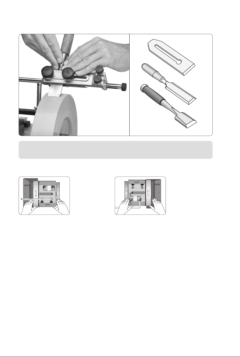
See illustration on the next page. The jig comprises an upper base with a lower clamp
and two locking knobs for xing the tool. The jig slides on the Universal Support on nylon
bushings across the grinding wheel. The edge angle is set with the Micro Adjust (3) on the
Universal Support (4).
There are two safety stops to prevent the tool from slipping off the wheel when grinding.
One inner stop (1) to be positioned according to the width of the tool and one outer stop (2)
mounted on the end of the Universal Support.
The jig lines up the chisel to its upper at side, making it easier to mount it correctly (not
twisted). Conventional jigs need manual alignment.
The lower clamp has a ridge in the centre enabling shorter tools with a tapered shank to be
rmly mounted, e.g. Japanese chisels. The upper base, which lines up the tool, is designed
so the clamping pressure is distributed to the ends and the tool mounts rmly without a
heavy tightening of the knobs.
Square Edge Jig SE-77 (SE-76)
PLANE IRONS
WOOD CHISELS
Max width 77 mm (3")
Max thickness 9 mm (
⅜
")
SE-77 is a further development of SE-76. The jig now has an adjustable side.
121
Before you start grinding,
check that the stone is true
by letting the Universal
Support touch the stone.
If necessary, true it with the
Truing Tool TT-50 so the sur-
face is flat and parallel to the
Universal Support.
Preparations
The jig lines up the chisel to
its upper and flat side. Thanks
to the shoulder (A) it is easy to
mount the tool correctly at 90°.
The clamping pressure from the
ridge in the centre is distributed
to the edges. This gives a firm
mounting, even with tapered
chisels.
SE-77: The two smaller adjust-
ment screws (5) are used if you
need fine adjustment to achieve
a 90° angle, or if you want
a slightly convex shape
(page 125).
122
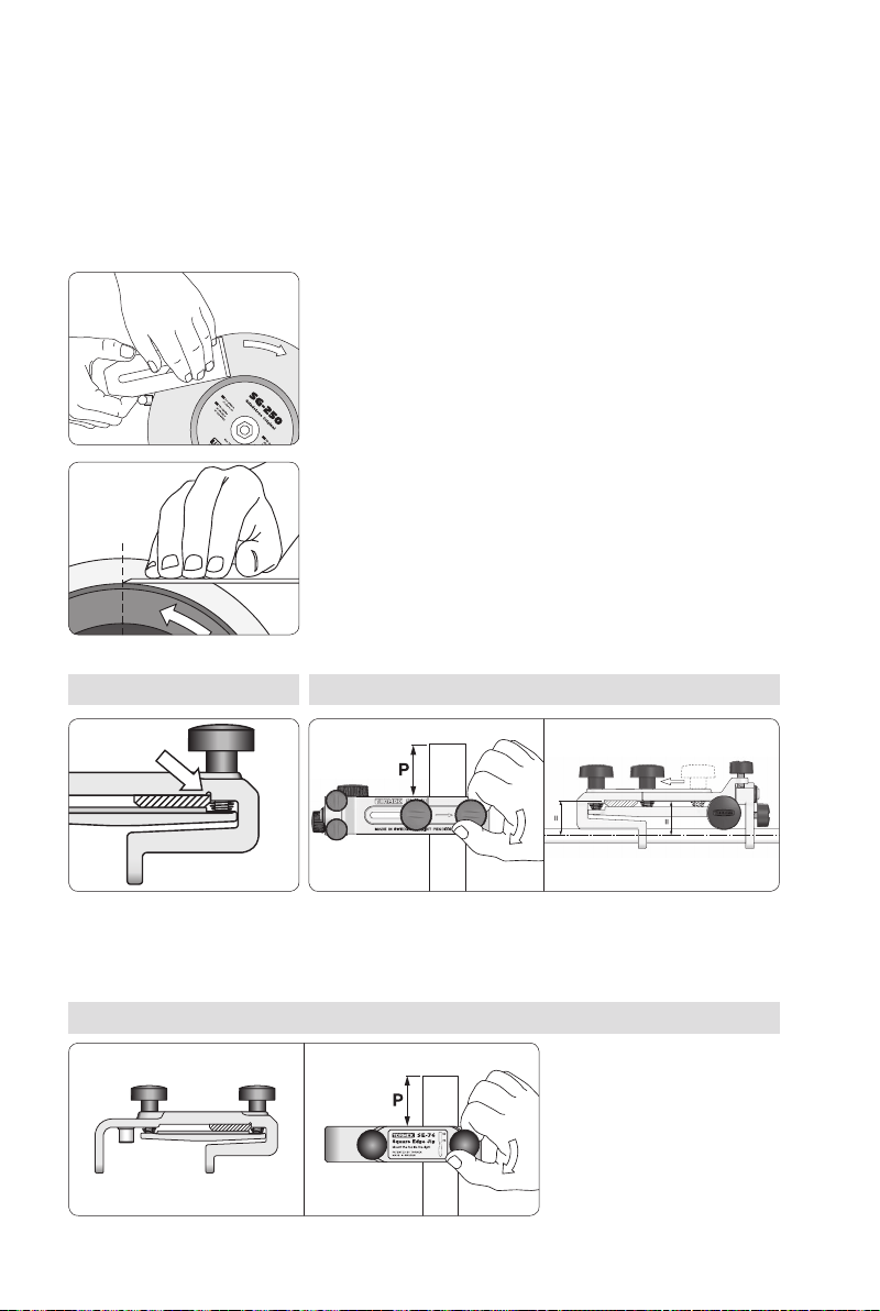
Open the clamp to the thick-
ness of the tool and approxi-
mately parallel to the base.
Mount the tool protruding (P)
approx. 50–75 mm (2–3").
Lock the tool by tightening
the knob nearest to the
tool only.
SE-76: Mounting the tool
Flatten and hone the back of the tools
To achieve a really sharp and durable edge, both of the two converging surfaces must be
smooth. If we sharpen and hone the bevel to perfection but the back is not equally at and
smooth, you will never achieve a satisfactory result. On most new tools, the back has visible
grooves from the manufacturing process. These should be removed and the surface honed
and polished. This work only needs to be done once, when you start using the tool. It is a
good investment in your quality tool and will last its lifetime.
Carefully position the tool against the wheel. The edge must
not touch the wheel before the heel! Flatten the back of the tool
by holding it flat to the grinding wheel while moving it slightly.
Otherwise the tip can cut into the wheel and be rounded off.
Let the side of the tool rest on the Universal Support, which
should be placed close to the wheel as shown. You do not need
to smooth the tool more than 25–30 mm (1–1¼") from the edge.
Working freehand, hone and polish the surface on the leather
honing wheel. Hold the tool so it is a tangent to the wheel.
Mount the tool protruding (P) approx. 50–75 mm or 2–3".
Lock the tool by tightening the movable knob about 5 mm
from the tool.
Tools with parallel sides
must rest on the shoulder.
For mounting tools without
parallel sides, see page 124.
SE-77: Mounting the toolSE-77 and SE-76
123
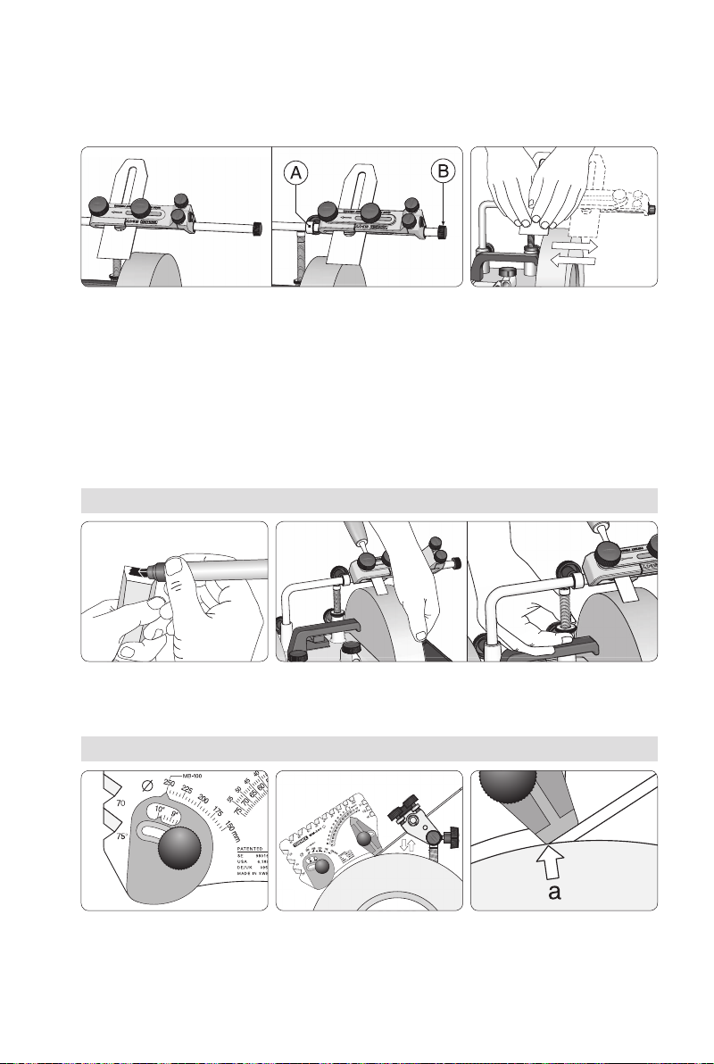
Colour the bevel with a marker. Turn the grinding wheel by hand and check where the grinding
will take place. Adjust with the Micro Adjust until the wheel touches the entire bevel from the tip
to the heel.
Sharpening an existing edge angle
Setting the edge angle
The height of the Universal Support determines the edge angle. This can be set in two ways.
Either you can exactly replicate the existing angle using the Marker Method or you set to a
new angle according to your choice using the Tormek AngleMaster WM‑200.
Set the AngleMaster WM-200
to the diameter of your wheel.
Set the height of the Universal
Support with the Micro Adjust.
Note! The entire base should
rest on the tool with the corner
(a) on thewheel.
Sharpening a new edge angle
First mount the inner, movable stop (A) so the tool rests with
approx. 6 mm or ¼" on the wheel. Then mount the outer stop (B),
which is fixed and independent of the tool width.
Move the tool continuously
between the two stops.
Spend moretime sharpen-
ing the sides.
Setting the safety stops
The safety stops ensure security when using the wheel’s full width and should be used when
sharpening plane irons, since these are partly moved outside the wheel. The inner stop (A)
is removed when sharpening blades wider than 60 mm or 2⅜".
124
Sharpening
Japanese Chisels
These differ in shape from the Western style chisels. The
rough shape from the forging is retained without machining,
the sides are usually not parallel and the blades are shorter.
This means that you cannot use the alignment shoulder in
the jig for an exact 90° alignment. The clamp is designed
so tools with a tapered shank can also be rmly mounted
(page 121). Be cautious when sharpening Japanese chis‑
els! Compared to longer Western style chisels there is a
limited amount of available steel, so you should set carefully to minimize the removal of
expensive steel. The back has a hollow, which moves closer to the edge at each sharpening.
After some sharpenings you might need to atten the back, so the hollow does not reach
the edge. Then use the side of the wheel.
Draw a pencil line on the
stone using the Universal
Support as guide.
Align the tool to the
line when mounting.
Ensure that the hollow does not
reach to the edge. If neccessary,
flatten the back on the side of
the grinding wheel. Important!
Bring the tool to the wheel care-
fully when flattening the back.
The edge must not touch the
wheel before the heel.
Move the tool sideways to use the whole width of the wheel.
Donot move more than approx. 2 mm (
4
") outside the wheel.
Press with your fingers close to the edge for best control.
Ahigher grinding pressure means faster steel removal. Lighten
the pressure at the end of the sharpening and you will obtain
afiner surface.
Sharpen until a burr develops
on the entire bevel. You can
feel it with your finger.
Important You control with your hands – the pressure and grinding time –
where the grinding takes place. Check the shape frequently and grind more
where it is needed.
125
Factors that influence the result
To get a 100 % straight edge when sharpening wide tools
such as a plane iron, you need to pay attention to a couple
of factors that inuence the result. The grinding jig gives
the tool a constant edge angle towards the stone but the
shape achieved depends on how much pressure you apply
on the right or left side. Also the time you spend sharpening
on each side inuences the shape.
If you press equally on both sides and move the tool evenly across the stone, you will get
a concave and not a straight edge. This is because the middle part is exposed to a longer
sharpening time than the sides. Compensate for this effect by spending more time sharpen‑
ing on the sides.
Camber Shape
Most types of plane irons should have a slight convex
shape or a camber. The degree of camber depends on
type of plane and should be approximately the same as
the thickness of the shavings. The camber (c) varies from
0.8 mm (2") for a jack plane down to 0.05 mm (0.002") for
a smooth plane.
The camber is achieved by pressing harder on the sides. A
longer protrusion of the blade in the jig will facilitate this effect, as most plane irons are a bit
exible. On a thick, stiff tool you create the camber shape by spending more time sharpen‑
ing on the sides.
SE-77 Adjustment screws
For tools with a larger convexity you can use the adjustments screws, see below. If you need
additional convexity, sharpen free hand with the Tool Rest SVD‑110.
Loosen equally on the adjust-
ment knobs A and B. The side
then gets a pendulum motion.
The more you loosen the knobs,
the greater pendulum motion
you get, which increases the
convexity.
Center the tool under the jig’s center line, marked with a line.
Ensure that the tool is mounted perpendicularly by drawing a
line along the Universal Support (page 124).
126
Press the fine side of the Stone
Grader onto the stone for about
45 seconds. Use a fair amount
of pressure.
Use the same setting and fine
sharpen for 30–40 seconds.
Donot press too hard.
Finer Surface with the Stone Grader
You can rene the tool surface by grading the Tormek Original Grindstone with the ne side
of the Tormek Stone Grader SP‑650. Pressing the Stone Grader rmly towards the grind‑
stone renes the grindstone surface so it acts like a 1000 grit stone. If you are replicating an
established edge angle, you can go directly to this ner surface of the stone.
SE-77 Fine adjustment
For increased sharpening
pressure on the tool’s right
side, loosen knob A and tighten
knob B. Do the opposite for
increased sharpening pressure
on the left side. Adjust approxi-
mately ¼ turn until you get a
desired result.
The adjustment screws create a
movable side which allows fine
adjustment. They can be used if
you do not get a 90° angle.
When the lines meet, the jig
is in its neutral position.
Honing on the leather honing wheel
Turn the machine around so that the honing wheel rotates
away from you. Move the Universal Support to the honing
wheel side and mount horizontally. Set to the same honing
angle as the grinding angle. Use the Bevel Marker Method
or the AngleMaster WM‑200 for the setting, see page 123.
Remember to change the AngleMaster’s diameter to ∅220
mm. The jig gives you full control of the honing angle on
the T‑8 model. Hone the back of the tool without the jig.
The safety stops are not used when honing – they are designed for use on the grinding
wheel. Therefore, check that you do not slide the jig too far sideways. A part of the blade
must always be in contact with the wheel.
127
Secondary Bevel?
Some people recommend that you should put a secondary bevel (or microbevel) on your
plane irons and wood chisels. The reason is that the honing work after the grinding is quicker
since you do not need to hone the entire surface of the bevel, just the smaller new bevel
at the tip.
For wood chisels there is a drawback with a secondary bevel since you do not have the
support of the large original bevel to control the cutting in the wood.
Since the grinding and honing of the entire bevel with the Tormek method is an easy and fast
operation, there is no need for a secondary bevel. With a single bevel, you can set exactly
the angle that you want and easily maintain it at every grinding and honing.
Reduced support length
with a secondary bevel
on a wood chisel.
Support length with
a monobevel.
Hone the back free hand. Hold
the tool so that it is at a tangent
to the wheel.
Do not hold the tool at a
steeper angle than the tangent!
The tip will be rounded off.
Edge Angle
Plane irons, wood chisels and spoke shave blades are
usually ground with a 25° edge angle (α). If you need to
work delicate details with a wood chisel in soft wood, you
can decrease the edge angle down to 20°. If you work in
hard wood and when using a mallet, you must increase the
edge angle to 30°.

Other tormek Power Tools manuals

tormek SVD-185 User manual

tormek

tormek SVD-185 User manual

tormek SVS-50 User manual

tormek

tormek SVS-50 User manual

tormek TTS-100 User manual

tormek

tormek TTS-100 User manual

tormek SE-76 User manual

tormek

tormek SE-76 User manual

tormek SVM-00 User manual

tormek

tormek SVM-00 User manual

Popular Power Tools manuals by other brands

Ryobi ONE+ RSI18 manual

Ryobi

Ryobi ONE+ RSI18 manual

Matco Tools EIGHTY8 CFR158G quick start guide

Matco Tools

Matco Tools EIGHTY8 CFR158G quick start guide

DeWalt DCH243 instruction manual

DeWalt

DeWalt DCH243 instruction manual

Hotronix FUSION IQ Operator's manual

Hotronix

Hotronix FUSION IQ Operator's manual

FINO 20123 Instructions for use

FINO

FINO 20123 Instructions for use

Dynabrade 52576 user manual

Dynabrade

Dynabrade 52576 user manual

laguna S45T manual

laguna

laguna S45T manual

DeWalt DCS367B instruction manual

DeWalt

DeWalt DCS367B instruction manual

Scheppach MFH5200-4P Translation of the original instruction manual

Scheppach

Scheppach MFH5200-4P Translation of the original instruction manual

Proluxe DP2010VPE Operation manual

Proluxe

Proluxe DP2010VPE Operation manual

Yokota Y-56E-JQ manual

Yokota

Yokota Y-56E-JQ manual

Wacker Neuson DPU 6055 Operator's manual

Wacker Neuson

Wacker Neuson DPU 6055 Operator's manual

Dentsply Sirona Multimat Cube instruction manual

Dentsply Sirona

Dentsply Sirona Multimat Cube instruction manual

Makita BJN160 instruction manual

Makita

Makita BJN160 instruction manual

Westfalia J1ZE-KZ-13 instruction manual

Westfalia

Westfalia J1ZE-KZ-13 instruction manual

Milwaukee C18 PCG Original instructions

Milwaukee

Milwaukee C18 PCG Original instructions

Bosch GSH 11 VC Professional Original instructions

Bosch

Bosch GSH 11 VC Professional Original instructions

Fein BLK1.3TE Repair instructions

Fein

Fein BLK1.3TE Repair instructions

manuals.online logo
manuals.online logoBrands
  • About & Mission
  • Contact us
  • Privacy Policy
  • Terms and Conditions

Copyright 2025 Manuals.Online. All Rights Reserved.