Tornado T7/Vision 2/S User manual

1
WARNING
TORNADO powered respirators are designed for use by personnel who are
familiar with workplace hazards.
This leaflet must be read together with the user leaflet for T/POWER and
T/FILTER.
DO NOT use in confined spaces, oxygen deficient atmospheres (<19.5%),
oxygen enriched atmospheres (>23%) or areas where there is an immediate
DANGER to life or health
DO NOT use if the mask or air hose is damaged, the filter is clogged or the
filter is time expired (see filter label).
DO NOT use with a low airflow output.
T7/VISION 2 is not approved for use with T/A/LINE.
DO NOT modify facemasks as this will invalidate all approvals and may
result in death or injury to the wearer.
Protection will only be obtained if the unit is fitted correctly.
In the unlikely event of T/Power failing while in a hazardous atmosphere,
there may be a reduction in airflow within the facepiece. DO NOT remove
the facepiece. GO IMMEDIATELY to a safe area then remove the facepiece.
It is unlikely that the requirements for leakage will be achieved if hair,
spectacle side arms or clothing intrude into the faceseal.
T7/VISION 2 SPECIFICATION
Facepiece T7/VISION-S/M/ML
Description FullFacemask
Classification: T7/VISION2
Visor EN12942TM3
MeetsimpactrequirementsofEN166GradeB
Minimumdesignflowrate 110L/min
Assigned*protectionfactor
Nominalprotectionfactor
40
2,000
Operatingtemperaturerange -10°Cto40°C
Storagetemperaturerange 10°Cto40°C
Facesealmaterial Siliconeelastomer
*According to BS4275 : 1997

2
DESCRIPTION
Vision 2 is a full facemask that conforms to EN12942 TM3. There are three size versions of the mask:
T7/VISION 2/S (small)
T7VISION 2/M (medium)
T7/VISION 2/ML (medium large)
With an option of standard head harness or PN (Polynet).
The face seal and neckstrap are silicone elastomer and the headharness is EPDM. The coated
polycarbonate visor meets the impact requirements of EN166, Grade B.
The inner mask, with speech diaphragm, reduces carbon dioxide dead space and minimised visor
misting. The maximum weight of the mask without the air hose is approximately 730 grams.
In use, filtered air from the Tornado blower is delivered via an air hose, over the inner surface of the visor
(keeping it clear of misting) and into the inner mask through inlet valves. Exhaled air flows out of the
inner mask through the exhale valve to the atmosphere.
Vision 2 is easily dismantled for repair and servicing, requiring only a pozi-drive screwdriver to undo the
front fitting. Servicing should only be carried out by trained, authorised personnel.
USING T7/VISION 2
1. Check that the facemask, inhale and exhale valves and head harness are clean and undamaged.
2. Check that the filter(s) fitted are not clogged or time expired and are suitable for the hazards that
may be encountered. If necessary fit new filter(s). Check that a filter seal(s) is in place and is in
good condition. Replace if necessary.
3. Check that the exhale valve is clean and in good condition. Check that the valve flap is not
distorted.
4. Hang the mask around your neck by the neckstrap, fully slacken the head harness and remove the
filter cover. The neckstrap pin can be prressed into the hole at the top of the head harness to
support the facemask in an upright attitude, keeping it free from dust and debris when the mask is
not in use.
5. Hold the head harness with the thumbs inside the harness. Fit the chin into the chin-cup and then
pull the harness over the head. Gently tighten the harness straps: lower first, then the middle
straps and then the top strap. A good seal should be achieved without over tightening, which will
cause the facemask seal to distort and cause discomfort.
6. Check the face to mask seal before connecting the blower air hose by blocking the mask inlet and
breathing in. The mask should pull onto the face. Hold your breath for 10 seconds and check that
the mask seal is maintained over the 10 seconds. If the seal fails, indicated by the mask pulling
away from the face, adjust the mask seal to the face, then repeat the test. If it fails a second time
the mask should be serviced.
WARNING If the mask does not seal after servicing, it MUST NOT be used.
7. Connect the hose to the facemask, check that the elbow is at a suitable angle and tighten the nut.
8. Arrange the breathing hose so that it trails freely down the back and is not kinked or likely to snag.
9. See the T/POWER leaflet for further user information.
AFTER USE
1. DO NOT remove the facemask until well clear of the hazard area.
2. The mask must be cleaned after use. DO NOT use solvent, detergent or abrasive cleaners that
may damage the mask. After any service procedure the leak test described above must be
performed to ensure that the mask is safe to use.
3. Replace the filter cover. Check that the filter is not clogged, saturated or time expired. If it is either
clogged, saturated or time expired, renew it.

3
4. Detach the air hose from the facemask and use a synthetic sponge moistened in a warn solution of
water and TriGene to clean and sanitise it.
Note: Water MUST NOT enter the hose.
5. Sponge the facemask with a synthetic sponge moistened in a warn solution of water and TriGene
to clean and sanitise it. Take care not to scratch the visor.
6. Flush the exhale valve under clean running water and check that it is in good condition.
7. Hang the mask by the head harness away from direct sunlight and high temperatures until it is
completely dry. Store it carefully to ensure that the visor will not be damaged, in a cool, clean, dry
store, away from direct sunlight.
8. Perform the leak test as described in Using T7/Vision 2, sub-section 6.
MAINTENANCE
Maintenance tasks must only be performed by trained personnel. Contact Protector for training
information. Following servicing, mask integrity can be checked using the Protector Respirator Test
Equipment. Contact Protector Internal Sales (+44 (0) 1695 711711) for details on Service Providers.
FACESEAL AND INNER MASK – During pre and post use inspections and at the stipulated
maintenance intervals, inspect for holes, surface damage or excessive distortion, particularly around the
face seal. Replace as necessary.
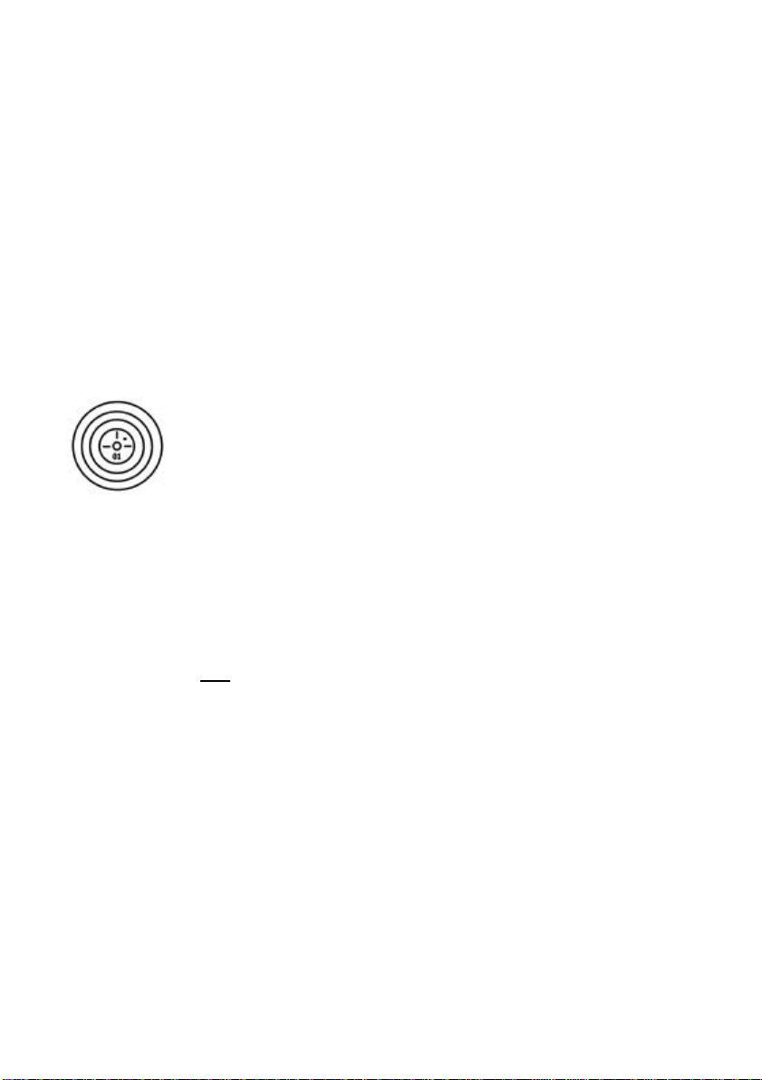
Fig 1
EXHALATION VALVES – These should be as new with no damage. The valves
are marked with a code indicating the year and year quarter of manufacture (see
Fig 1). The two digit number stamped on the valve is the year of manufacture.
The dot, stamped in one of the four quadrants is the quarter of the year in which
manufacture took place. Top right (in relation to the year digits) = Jan to March,
bottom right = April to June, bottom left = July to September and top left =
October to December. Exhalation valves should be replaced at least annually,
regardless of condition.
HEADHARNESS – This should be checked for possible failure, paying particular attention to the anchor
studs. The EPDM headharnesses are stamped on the outside centre, with a code indicating the date of
manufacture. The number in the centre is the year of manufacture and the dots around the outside of
the number indicate the month of manufacture during that year. Therefore the number ‘00’ with seven
dots around it is July 2000.
NOTE: REPLACEMENT INTERVALS FOR COMPONENTS MARKED WITH A DATE OF
MANUFACTURE SHOULD BE CALCULATED FROM THE DATE OF FIRST USE OF THE
COMPONENT AND NOT THE DATE OF MANUFACTURE.
RECORD INSPECTION AND MAINTENANCE DETAILS
Record test and maintenance details on the Inspection and Maintenance Record Sheet (appendix A)
Information recorded usually includes:
1. Name of employer responsible for the apparatus.
2. Make, model number or identification mark of the apparatus, together with a description of any
distinguishing features, sufficient to enable clear identification.
3. The date of the inspection/maintenance together with the name, signature or unique
authentication mark of the examiner.
4. The condition of the apparatus and details of any defects found and any remedial action taken,
SHELF LIFE OF COMPONENTS
O-rings spares packs are marked with a shelf life. DO NOT use O-rings from spares packs with a shelf
life expiry date that has passed. O-rings must be replaced at least annually, regardless of condition.

4
NOTE: REPLACEMENT INTERVALS FOR COMPONENTS ORIGINATING FROM A SPARES PACK
MARKED WITH A SHELF LIFE MUST BE CALCULATED FROM THE DATE OF FIRST USE OF THE
COMPONENT AND NOT FROM THE SHELF LIFE EXPIRY DATE.
NOTE: FOR CALCULATING PERIODIC MAINTENANCE DATES THE ‘DATE OF FIRST USE’ IS THE
DATE ON WHICH THE END USER TAKES DELIVERY OF A COMPLETE VISION 2 FACEMASK
FROM THE SUPPLIER OR IN THE CASE OF SPARES, THE DATE ON WHICH THE
REPLACEMENT COMPONENT IS FITTED TO THE VISION 2 FACEMASK.
REPLACEMENT OF VISOR
1. Release head harness and remove from facemask.
2. Remove the screws from the front cover (1) and remove front fitting from inside of mask. Unscrew
the two visor clamp screws (10), remove the visor clamps and the visor.
3. Inspect O-ring (5) and if necessary replace. Lubricate new O-ring with MS4 silicone grease.
4. Position the visor over the front fitting, ensuring that the hook on the front fitting engages outside
the visor. Fit the tab at the top of the visor through the slot at the top of the silicone outer mask and
feed the visor into the groove in the outer mask.
5. Fit the visor clamps and secure with screws and nuts. Replace front cover (1) and secure with
screws. Ensure that the front fitting encloses the visor rim and beds smoothly onto the front of the
body front fitting (7).
6. Fit head harness.
Replacement of Inhale Valve
1. Push out the inhale valve (4) from inside the facemask.
2. Fit the new valve flap (3) over the valve frame boss. Push the inhale valve assembly into the
facemask breathing hose inlet and check that the flap lies flat on the valve frame.
Replacement of Exhale Valve
1. Remove the front fitting (7) and push the exhale valve assembly from inside the mask, out through
the front fitting. Check that the flap and O-ring are in good condition. If necessary replace both.
2. If the O-ring is replaced it must first be lubricated with MS4 silicone grease.
Replacement of Inner Mask Inhale Valves
The valve flaps are located on the inner side of the inner mask
1. Carefully pull the inhale valve flaps and valve pins (18) from inner mask (19). Clean the inner mask
and fit new valve flaps.
2. Check that the valve flaps move freely on the pin and lie flat on the inner mask.
Important:
Check the valve flaps before each use to ensure that they are clean and undamaged.
Check that the inhalation valve flaps are flexible.
Valves and O-rings must be replaced if they are damaged in any way and at least annually,
regardless of condition.
Storage Note: Rubber components should always be stored in clean, dry conditions away from
direct sunlight and heat.
Replacement of Speech Diaphragm
1. Rotate the speech diaphragm retainer (19) 10° anti-clockwise and withdraw the retainer, speech
diaphragm and O-ring (8). Check that the speech diaphragm is in good condition and replace if
necessary. Lightly lubricate the replacement O-ring with MS4 silicone grease.

5
2. Fit O-ring (9) over the speech diaphragm and press the diaphragm and O-ring into the front fitting,
black grid first, taking care to ensure that the O-ring stays in place on the diaphragm. Secure with
the retainer for the speech diaphragm, with apron uppermost.
Replacement of Inner Mask
Gently pull the inner mask from the front fitting (7) and feed the rim of the new inner mask into the
groove in the front fitting (7).
Replace the front cover and tighten the two retaining screws (1) evenly.

6
SPARE PARTS
Item numbers refer to the exploded view at the front of the book and bracketed number in maintenance
descriptions. Bracketed numbers show the number of items per spare pack.
ITEM DESCRIPTION PART NO.
1Front cover and screws (1) RXFC/T7VIS
2Visor and side fittings (1) 071.835.89
Valve flap inhale (5) 071.736.98
3Valve flap inhale and exhale kit (1 set) 071.736.99
4Valve frame and pin inhale (1) 071.705.89
5O-ring for front fitting (5) 054.235.89
6Exhale valve, complete assembly 071.212.99
Valve flap exhale (5) 071.124.99
O-ring for Exhale valve 054.066.99
7Front fitting and inserts (1) 071.695.99
8Speech diaphragm, complete assembly with o-ring (1) 071.211.85
9O-ring for Speech diaphragm (5) 054.067.89
10 Clamp screws and nuts for M/L (1) 071.710.89
Clamp screws and nuts for M (1) RX/CLAMPS/VIS/M
Clamp screws and nuts for S (1) RX/CLAMPS/VIS/S
11 Mask hinge, 3 upper and 2 lower (1 set) 071.708.89
12 Face seal M/L (1) 071.702.89
Face seal S (1) 071.868.89
13 Neckstrap (1) 071.733.89
14 Buckles and rollers (5) 071.707.89
15a Head harness 071.704.89
15b Head harness Polynet 071.898.89
16 Stirrup, rubber link and top mount 071.751.89
17 Inner mask and valves L (1) 071.712.89
Inner mask and valves S/M (1) 071.875.89
18 Inhale valve flaps (6) 017.114.29
19 Retainer for Speech diaphragm (1) 071.694.89
MS4 silicone grease 074.101.02
TriGene - 1 litre 013.028.00
NOTIFIED BODY Inspec Certification Ltd (Number 0194),
Upper Wingbury Courtyard, Wingrave, Aylesbury,
Buckinghamshire, HP22 SLO, UK
This manual suits for next models
2
Table of contents