manuals.online logo
Brands
  1. Home
  2. •
  3. Brands
  4. •
  5. Toro
  6. •
  7. Control Unit
  8. •
  9. Toro P220 SERIES User manual

Toro P220 SERIES User manual

Introduction
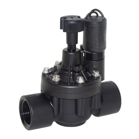
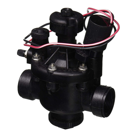
Built on proven technologies and components, the ToroP 220 Series plastic
valves are tough, have excellent performance and are extremely reliable.
Aself-cleaning metering system and 220 PSI rating assures years of
trouble-free performance.
In commercial installations, it is advantageous to install the valves in a
valve box. This enables the valve to be located, accessed and maintained
easily. The use of clean aggregate in the the bottom of the box, and
keeping valve box locations away from structures, potential hardscaping
features (such as sidewalks) and large planting locations is recommended.
Additionally, valve box locations generally should be in shrub beds and at
right angles to structure locations. If the valves are installed below grade
without a valve box, access to the top of the valve should be provided using
a section of 4" PVC pipe and a Toro Valve Cover (Part No. 850-00) installed
directly over each valve.
P220 Series Plastic Valves
Installation Instructions
Specifications
■Models:
❚220 Series electric, 1", 11⁄4", 11⁄2", 2", 21⁄2", 3”
❚220 Series electric pressure regulating, 1", 11⁄4", 11⁄2", 2”,
21⁄2", 3"
■Flow range:
❚1" —5-40 GPM
❚11⁄4" —20-100 GPM
❚11⁄2" —20-130 GPM
❚2" —30-180 GPM
❚21⁄2" —60-250 GPM
❚3" —80-350 GPM
■Operating pressure:
❚Electric models: 10-220 PSI maximum
❚Pressure-regulating models:
–Outlet: 5-30 PSI, ±3 PSI
(EZR-30)
5-100 PSI, ±3 PSI
(EZR-100)
–Inlet: 15-220 PSI
■Minimum pressure differential (between inlet and outlet):
10 PSI
■Burst pressure safety rating: 750 PSI
■Body styles:
❚Globe valve —1", 11⁄4", 11⁄2", 2" female threads
❚Angle valve —21⁄2", 3" female threads
❚BSP threads available
■Solenoid: 24 V a.c.
❚Inrush: 0.40 amps, 11.50 VA
❚Holding: 0.20 amps, 5.75 VA
■Dimensions:
❚1" —53⁄4" H x 5" W
❚11⁄4" —61⁄2" H x 6" W
❚11⁄2" —61⁄2" H x 6" W
❚2" —71⁄2" H x 5" W
❚21⁄2" —83⁄4" H x 81⁄2" W
❚3" —83⁄4" H x 81⁄2" W
■220 PSI maximum pressure rating
■Ingot brass and stainless-steel construction
■Removable, self-flushing, contamination-proof, 120-
mesh, stainless-steel filter screen (electric models)
Voltage Requirement (standard solenoid)
Voltage Inlet Pressure
22.5 V a.c. 220 PSI
21.1 V a.c. 200 PSI
20.2 V a.c. 175 PSI
19.1 V a.c. 150 PSI
18.2 V a.c. 125 PSI
17.1 V a.c. 100 PSI
16.1 V a.c. 75 PSI
16.0 V a.c. 50 PSI
Specifications (continued)
■Precise pressure control with compact EZReg dial design
■Pressure regulates in electric and manual modes, serviceable
under pressure
■Schrader-type valve for pressure gauge attachment
■Manual flow control: adjustable to zero flow
■Manual bleed screw: bleeds internally downstream
Note: For optimum performance, calculate total friction loss to
ensure sufficient downstream pressure.
Friction Loss
Flow (GPM)
Model 5 10 15 20 30 40 50 60 70 80 100 120 150 170 180 200 250 300 350
1" 2.0 2.5 1.5 2.5 5.5 7.0
11⁄4" 5.5 6.5 7.5 8.0 8.5 9.0 13.0 16.0
11⁄2" 4.0 5.2 5.4 6.0 6.5 7.0 8.0 10.0 15.0
2" 1.0 2.0 2.0 2.5 3.0 3.5 6.0 7.5 10.0 12.0 14.0
2-1⁄2" 2.0 2.2 2.3 2.4 2.5 3.0 4.0 4.5 5.5 7.0
3" 2.2 2.4 2.5 3.0 4.0 4.5 5.5 6.5 7.0 7.5
Installation Guidelines
•Note the flow direction arrow in the side of the valve body and install accordingly.
•The valve can be installed at any angle without affecting operation.
•Use direct-burial wire, utilizing different color codes for each station control wire and one color for the common wire to all
valves.
•Waterproof wire splice connectors are absolutely essential for proper electric control system operation. Follow the
installation instructions provided with the connectors for optimum waterproof splice protection.
•Leaving a wire expansion loop at each valve location on long-run wire lengths is recommended.
Valve Operation and Adjustment
Flow Control
The flow control is used to reduce the flow and pressure to valve outlet. By turning the control handle clockwise, the flow will
gradually be reduced zero.
•For valve models without EZReg, adjust the flow control as necessary for optimum sprinkler performance.
•For valve models with EZReg, the flow control should remain in the fully open position. Use only for emergency shut off.
Manual Bleed Knob
The manual bleed knob is used to manually operate the valve. Turning the knob counterclockwise 2–3 turns allows water to
bleed downstream from the diaphragm chamber, relieving pressure from the top of the diaphragm which allows the valve to
open. Turning the bleed knob clockwise until finger tight, shuts off the discharge enabling pressure to build within the
diaphragm chamber, causing the valve to close.
EZReg (pressure regulated models only)
An accurate, adjustable dial coupled with a forward-flow valve design allows the 220 series valve with EZReg to regulate
downstream water pressure with precision. It can regulate accurately down to 5 GPM flow (1" model) and only requires 10 PSI
differential pressure to operate.The EZReg will operate during powered and manual valve operation.
To adjust, remove the cover from the regulator dial. Turn the dial until the pointer is on the desired downstream pressure:
5–30 PSI (EZR-30) or 5–100 PSI (EZR-100).
Note: Due to the micro-adjustment feature of the EZReg, the dial requires several complete revolutions to move the pointer
from the minimum to the maximum adjustment settings.
Operate the valve (electrically or manually). Check the flow control to confirm that it is in the fully open position.Adjust the
regulator dial if necessary for optimum sprinkler operation.
To confirm the downstream pressure using a pressure gauge, remove the cap from the Schrader-type valve located directly
below the EZReg.Attach a Toro pressure gauge (Model 995-51) to the Schrader-type valve for a direct reading.Adjust EZReg
dial as necessary for the desired pressure.
Note: The valve will remain operational if removal of the EZReg assembly is required.
© 1999 The Toro Company, Irrigation Division Form Number 373-0027 Rev A
Note: For optimum performance, calculate total friction loss to ensure sufficient
downstream pressure.
Friction Loss
Flow (GPM)
Model 5 10 20 30 40 50 60 70 80 90 100 110 120 130 140 50 180 200 225 250 275 300
1" Globe 4.00 4.20 3.20 4.10 7.20 10.90
1"Angle 4.00 4.20 3.10 2..70 4.80 7.90
11⁄2" Globe 4.00 4.20 3.10 2..70 4.80 7.90
11⁄2"Angle 1.6 2.3 3.6 5.2 7.0 9.2 11.7 14.4 17.5
2" 1.0 2.0 2.0 2.5 3.0 3.5 6.0 7.5 10.0 12.0 14.0
3" 2.2 2.4 2.5 3.0 4.0 4.5 5.5 6.5 7.0 7.5

Other Toro Control Unit manuals

Toro 53799 User manual

Toro

Toro 53799 User manual

Toro TPV Series Operating instructions

Toro

Toro TPV Series Operating instructions

Toro EZ-Flo Plus EZF-29-03 User manual

Toro

Toro EZ-Flo Plus EZF-29-03 User manual

Toro 102-2012 User manual

Toro

Toro 102-2012 User manual

Toro P220G Series User manual

Toro

Toro P220G Series User manual

Toro LoRa Tempus Air MS User manual

Toro

Toro LoRa Tempus Air MS User manual

Toro 112-4881 User manual

Toro

Toro 112-4881 User manual

Toro 74946 Quick start guide

Toro

Toro 74946 Quick start guide

Toro 53380 User manual

Toro

Toro 53380 User manual

Toro 220G Series User manual

Toro

Toro 220G Series User manual

Toro E101B Installation manual

Toro

Toro E101B Installation manual

Toro 53380 User manual

Toro

Toro 53380 User manual

Toro 53381 User manual

Toro

Toro 53381 User manual

Toro 53682 User manual

Toro

Toro 53682 User manual

Popular Control Unit manuals by other brands

Feig Electronic cVEND plug Installation

Feig Electronic

Feig Electronic cVEND plug Installation

MG R7L-EA16 instruction manual

MG

MG R7L-EA16 instruction manual

LOVATO ELECTRIC EXS0000 instruction manual

LOVATO ELECTRIC

LOVATO ELECTRIC EXS0000 instruction manual

Rtelligent R110PLUS user manual

Rtelligent

Rtelligent R110PLUS user manual

Gira 5567 000 operating instructions

Gira

Gira 5567 000 operating instructions

Siemens 3AD8 instruction manual

Siemens

Siemens 3AD8 instruction manual

Honeywell SV2 Series user manual

Honeywell

Honeywell SV2 Series user manual

GE WIU-4 installation manual

GE

GE WIU-4 installation manual

Titan Controls HERCULES 702764 user guide

Titan Controls

Titan Controls HERCULES 702764 user guide

GBD SR302 Instructions for installation

GBD

GBD SR302 Instructions for installation

Measurement Computing Measurement Advantage USB-TC user guide

Measurement Computing

Measurement Computing Measurement Advantage USB-TC user guide

Würth ORSY mat FP operating instructions

Würth

Würth ORSY mat FP operating instructions

Chamberlain 79LM quick start guide

Chamberlain

Chamberlain 79LM quick start guide

Watts AMES LF960GD-15 Series installation manual

Watts

Watts AMES LF960GD-15 Series installation manual

Telit Wireless Solutions LM940 instructions

Telit Wireless Solutions

Telit Wireless Solutions LM940 instructions

Remak VCS Installation and operating instructions

Remak

Remak VCS Installation and operating instructions

National Instruments NI 9426 Getting started

National Instruments

National Instruments NI 9426 Getting started

Flywoo Goku Versatile F405 5IN1 AIO user manual

Flywoo

Flywoo Goku Versatile F405 5IN1 AIO user manual

manuals.online logo
manuals.online logoBrands
  • About & Mission
  • Contact us
  • Privacy Policy
  • Terms and Conditions

Copyright 2025 Manuals.Online. All Rights Reserved.