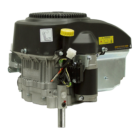
Toro Power Plus P216V User manual

ONAN TORO POWER PLUS P216V, 18V, 20V ENGINE - VERTICAL
Table of Contents – Page 1 of 2
SAFETY PRECAUTIONS
GENERAL
PROTECT AGAINST MOVING PARTS
BATTERIES
FUEL SYSTEM
EXHAUST SYSTEM
EXHAUST GAS IS DEADLY!
COOLING SYSTEM
KEEP THE UNIT AND SURROUNDING AREA CLEAN
CAUTION
GENERAL INFORMATION
INTRODUCTION
ENGINE MODEL REFERENCE
SPECIFICATIONS
DIMENSIONS AND CLEARANCES
ASSEMBLY TORQUES
SPECIAL TOOLS
ENGINE TROUBLESHOOTING
OIL SYSTEM
CRANKCASE OIL
OIL FILTER CHANGE
CRANKCASE BREATHER
PRESSURE LUBRICATION
OIL PUMP
OIL BYPASS CHECK BALL
FUEL SYSTEM
CARBURETOR
CARBURETOR SPEED SETTINGS
CARBURETOR OVERHAUL
REMOVAL
DISASSEMBLY
CLEANING AND REPAIR
REASSEMBLY AND INSTALLATION
PULSATING-DIAPHRAGM FUEL PUMP
FUEL PUMP TEST PROCEDURE
AIR CLEANER
GOVERNOR SENSITIVITY

ONAN TORO POWER PLUS P216V, 18V, 20V ENGINE - VERTICAL
Table of Contents – Page 2 of 2
IGNITION AND BATTERY CHARGING
IGNITION SYSTEM DESCRIPTION
IGNITION TIMING
CONTINUITY TEST
IGNITION COIL
SPARK PLUGS
BATTERY INSPECTION
BATTERY JUMP STARTING
FLYWHEEL ALTERNATOR
ALTERNATOR OUTPUT TEST
STARTING SYSTEM
ELECTRIC STARTER
SERVICE
STARTER REMOVAL
STARTER DISASSEMBLY
STARTER ASSEMBLY
INSPECTION AND TESTING
STARTER MOUNTING
ENGINE DISASSEMBLY
DISASSEMBLY/ASSEMBLY
VALVE SYSTEM
TAPPETS
VALVE FACE AND SEAT GRINDING
FLYWHEEL
GEAR COVER
GOVERNOR CUP
TIMING GEARS
PISTONS AND CONNECTING RODS
CYLINDER BLOCK
CRANKSHAFT
BEARINGS
CRANKSHAFT ENDPLAY
CHECKING CONNECTING ROD BEARING CLEARANCE
OIL SEALS
PISTON ASSEMBLY
INSTALLATION OF PISTON IN CYLINDER
CYLINDER HEADS

Service
Manual
1710
P216V,18V,2OV
Toro
Power
Plus
Engine
Tractors
& Riding Mowers

Safety
Precautions
It
isrecommendedthatyoureadyourenginemanualand
become thoroughly acquainted with your equipment before
you start the engine.
This symbol
if
used warns of imme-
diatehazards which will result in
severepersonal injury ordeath.
unsafe practice which can result In
This symbol refers
lo
ahazard or
severepersonal injury or death.
unsafe practice which can result in
This symbol refers
lo
ahazard or
personal injury or product orproperly damage.
Fuels,electricalequipment,batteries,exhaustgasesand
movingpartspresentpotentialhazardsthatcanresult in
serious, personal injury. Take careinfollowing these recom-
mended procedures. All local, state and federal codes should
be consulted and complied with.
tended for use in anytypeof aircraft.
This engine Isnot designed or in-
Use
of
thisengineinaircraft canresultinenginefailure
and causesserious personal injury ordeath.
General
Provide appropriate fire extinguishers and install themin
convenient locations. Use an extinguisher rated ABC by
NFPA.
Make sure that all fasteners on the engine are secure and
accurately torqued. Keep guardsin positionoverfans,
driving belts, etc.
If
itisnecessary to make adjustments while the engine is
running, use extreme caution when close to hot exhausts,
moving parts. etc.
Protect Against Moving Parts
Do
not wear loose clothinginthe vicinity
of
moving parts,
such as PTO shafts, flywheels, blowers, couplings, fans,
belts, etc.
Keepyourhands awayfrommoving parts.
Batteries
Before starting work on the engine, disconnect batteries
to prevent inadvertent starting
of
the engine.
DONOTSMOKEwhileservicingbatteries.Leadacid
batteries give
off
a highly explosive hydrogen gas which
can be ignited by flame, electrical arcing or by smoking.
Verify battery polarity before connecting battery cables.
Connect negative cable last.
Fuel System
DO NOT
fill
fuel tanks while engineisrunning.
DO NOT smoke or use an open flame
in
the vicinity
of
the
engine or fuel tank. Internal combustion engine fuels are
highly flammable.
Fuel lines must be of steel piping, adequately secured.
andfreefromleaks.Pipingattheengineshouldbe
approvedflexibleline..
Do
notusecopperpipingfor
flexible lines as copper will work harden and become
brittle enough to break.
Be sureall fuel supplies have a positive shutoff valve.
Exhaust System
Exhaust products
of
any internal combustion engine are
toxic and can cause injury,
or
death if inhaled.
All
engine
applications,especiallythosewithin
a
confinedarea,
should be equipped with an exhaust system to discharge
gases to the outside atmosphere.
Do
not use exhaust gases to heat a compartment
Makesurethat
your
exhaustsystem
is
free
of
leaks.
Ensure that exhaust manifolds are secure and are not
warped by bolts unevenly torqued.
Exhaust
Gas
is
Deadly!
Exhaust gases contain carbon monoxide, a poisonous gas
that can cause unconsciousness and death.
It
isan odorless
and colorless gas formed during combustion
of
hydrocarbon
fuels. Symptoms
of
carbon monoxide poisoning are:
Dizziness Vomiting
Headache Muscular Twitching
Weakness and Sleepiness Throbbing inTemples
If
you experience any
of
these symptoms, get outinto fresh air
immediately, shut down the unit and do not use until ithas
been inspected.
The best protection against carbon monoxide inhalation
is
proper installation and regular, frequent inspections
of
the
complete exhaust system.
If
you notice a changeinthe sound
or appearance
of
exhaustsystem,shutthe unitdown
immediately and haveit inspected and repaired at once by a
competent mechanic.
Cooling System
Coolants under pressure have a higher boiling Point than
water.
DO
NOTopenaradiatorpressurecapwhen
coolanttemperatureisabove
212°F
(l00°C)
orwhile
engine
is
running.
KeeptheUnitandSurroundingAreaClean
Make sure that oily rags are not left on or near the engine.
Removeallunnecessarygreaseand oilfromthe unit
Accumulated grease andoilcan cause overheating and
subsequent engine damage and present a potential fire
hazard.
E-6

Table
of
Contents
TITLE
PAGE
GeneralInformation
..................................................
. l-1
Specifications
...............................
.......................
.2-1
Dimensionsand Clearances
..........................................
.3-1
Assembly Torquesand Special Tools
..................................
.4-1
EngineTroubleshooting
..............................................
.5-1
Oil System
..........................................................
.6-1
Fuel
System.
...................................
....................
.7-1
Ignitionand Battery Charging
............................
............
.8-1
EngineWiring Diagram.
...................
..........................
.8-7
Starting System..
....................................................
.9-1
Engine Disassembly
................................................
10-1
I
EXHAUST GAS
IS
DEADLY!
Exhaust gasesfromallfuels (includingdiesel, gasoline, liquidpropane,natural
gas)contain carbonmonoxide,anodorlessandcolorlessgas. Carbonmonoxide
ispoisonous and cancause unconsciousnessand death. Symptomsof carbon
monoxidepoisoning caninclude:
Dizziness Throbbing in Temples
Nausea Muscular Twitching
Headache Vomiting
Weaknessand Sleepiness Inability
to
Think Coherently
IF
YOU
OR
ANYONE ELSE EXPERIENCE ANY OF THESE SYMPTOMS, GET OUT
INTO THEFRESH AIRIMMEDIATELY.
If
symptoms persist, seek medical
attention.Shutdownthe unit anddonot operate until ithasbeeninspected and
Protection against carbon monoxide inhalation includes proper installation,
ventilation andregular, frequent visual andaudible inspectionsof thecomplete
exhaustsystem.
repaired.
I

General
Information
INTRODUCTION
This manual dealswith specific mechanicaland elec-
trical informationneededbyenginemechanicsfor
troubleshooting,servicing,repairing,or overhauling the
engine.
Use the separate PARTS MANUAL forpartsidentification
and for establishingtheirproper locationon assemblies.
The PARTS MANUAL containsdetailedexploded views
of each assembly and theindividualpiece partnumbers
andtheir proper names for ordering replacementparts.
The illustrations and procedures presented in each
section apply
to
the engineslistedonthe cover. Theair
cleaner side of the engineisthefrontend. Right andleft
sides are determined by viewing the engine from the
front.The No.
1
cylinder isonthe right,
No.
2
cylinder is
on the left.
If
amajor repair or an overhaul is necessary,acompetent
mechanicshould either do thejob
or
superviseand
check the workof the mechanic assigned
to
the job
to
ensurethat all dimensions,clearancesandtorque
values arewithin the specified tolerances.
Use the table
of
contents for a quick reference
to
the
separate engine system sections.
Thetroubleshootingguide is provided
as
aquick
reference forlocatingand correcting enginetrouble.
The wiring diagram
shows
how the electrical compo-
nents are interconnected.
Thedisassembly sectioncontains major overhaul
proceduresforstepbystepremoval,disassembly,
inspection,repair,andassembly
of
theengine
components.
Use only Genuine
Tom
Plower Plus replacementpartsto
ensurequalityandthebestpossiblerepair andoverhaul
results. When orderingparts, always usethe complete
model and spec number as well
as
the serial number
shownon the nameplate.
ENGINE
MODEL
REFERENCE
Identify yourmodelby referring
to
'the modeland
specification (spec letter)as shown onthe unit name-
plate. Always use these numbers and the engineserial
number when making reference
to
your engine.
How
to
interpret MODEL andSPEC NO.
P
2 16
V
/
10464
A
12
3
6
7
1.
Factorycode for general identification of basic
engine series.
2.
Number of cylinders.
3.
BHP rating.
4.
Designation
(G
=
horizontal shaft,
V
=
vertical shaft)
5.
Engine duty cycle.
6.
Factory codefor designated optional equipment,
if
7.
Specification(spec letter) which advanceswith
any.
factory production modifications.
INCORRECT SERVICE
OR
REPLACEMENTOFPARTS CAN RESULT IN SEVERE
PERSONAL INJURY AND/OR EQUIPMENT DAMAGE. SERVICE PERSONNEL
MUST
BE
QUALIFIEDTO PERFORM ELECTRICAL AND/OR MECHANICAL
SERVICE.

Specifications
.
This manual contains
SI
metric equivalents that
follow
immediately inparentheses
after the
U.S.
customary units
of
measure.
UNITOF SERIES
SPECIFICATION MEASURE P216V P218V P220V
Number
of
Cylinders
2
2
2
Bore in
3.2503.2503.250
(mm)
(82.55)(82.55)(82.55)
Stroke in
2.625 2.875 2.875
Displacement CUin
43.3 47.7 47.7
Compression Ratio
6.5
to
1
7.0
to
1
7.0
to
1
Power at BHP
161820
RatedSpeed
(3600
rpm)
.
(kW)
(11.9)(13.4)
(1
4.9)
Oil CapacityQts
1.71.7.1.7
WithoutFilter(litre)
(1.6)
(1
(1.6)
Oil FilterCapacity
.3.3.3
Valve Clearance (Cold)
(mm)
(66.68) (73.03) (73.03)
(cm³)
(71
0)
(782)
(782)
Qts
(litre)
(.3)(.3)(.3)
__-
Intake in
.005
.005.005
Spark Plug Gap in
.025 .025.025
IgnitionTiming BTC
20° 20°20
(mm)
(.64)(.64)(.64)
CylinderCompression psi
75
to
11575
to
115
75
to
115
(kPa)
(517
to
793)51
7
to
793)(517
to
793)
2-
1

Dimensions
and
Clearances
All
measurementsgivenat roomtemperature
of
70°F (21°C)
.
All
measurementsare given in inches with approximate
millimeter measurementsin parentheses
.
Measurementsare
for
standardsize parts
.
DESCRIPTION
CYLINDER BLOCK
Cylinder BoreDiameter
....................................
PistonClearance
..........................................
MaximumAllowable
Taper
.................................................
Out-of-Round
.........................................
Top Main Bearing Bore
...................................
Top Main Bearing InsideDiameter(bearinginstalled)
........
Top MainBearing Clearance
..............................
Bottom Main Bearing Bore
.................................
BottomMain BearingsInside
Bottom Main BearingClearance
............................
Diameter(bearingsinstalled)
............................
Cam Bearing Bore
........................................
Cam Bearing InsideDiameter(bearinginstalled)
.............
Cam BearingClearance
..................................
Intake ValveSeat Bore
....................................
Exhaust ValveSeat Bore
..................................
Tappet BoreDiameter
....................................
Tappet Clearance
........................................
CRANKSHAFT
Top Main Bearing
Bottom Main Bearing
Journal Diameter
.......................................
Journal Diameter
........................................
EndPlay
................................................
ConnectingRodJournal Diameter
.........................
CONNECTING
ROD
Large BoreInsideDiameter(rodbolts torqued)
..............
Large BoreClearance
....................................
Piston Pin Bore
..........................................
Piston Pin Clearance
.....................................
EndPlay
................................................
CAMSHAFT
Journal Diameter
.........................................
Lobe Height
P216V.P218V Intake
...................................
P216V. P218V Exhaust
..................................
P220V Intake
..........................................
P220V Exhaust
.........................................
End
Play
................................................
3.2490 (82.52)
0.0033 (0.084)
2.1870
2.001
5
0.0024
2.1840
1.9990
0.001
0
1.4995
1.3757
0.001
5
1.4395
1.1
890
0.7500
0.0020
(55.55)
(50.84)
(0.061)
(55.47)
(50.77)
(0.025)
(38.08)
(34.94)
(0.038)
(36.56)
(30.20)
(1 9.05)
(0.051
)
1.9992(50.78)
1.9972 (50.73)
1.6252 (41.28)
0.0060
(0.1
52)
1.6280 (41.35)
0.0020 (0.051)
0.6879
(1
7.47)
0.0002
(0.005)
0.0020 (0.051)
1.3740(34.90)
0.01
10
(0.279)
MAXIMUM
Inches
(mm)
3.2500 (82.55)
0.0053
(0.1
35)
0.005
(0.1
3)
0.003 (0.08)
2.1880 (55.58)
2.0040 (50.90)
0.0042
(0.1
07)
2.1850
(55.50)
2.0020
0.0048
1
5005
1.3787
0.0030
1.4405
1.1 900
0.751 5
0.0040
(50.85)
(0.1
22)
(38.1
1)
(35.02)
(0.076)
(36.59)
(30.23)
(1
9.09)
(0.1 02)
2.0000
(50.80)
1.9980 (50.75)
1.6260 (41.30)
0.01 20 (0.305)
1.6285 (41.36)
0.0033 (0.084)
0.6882
(1
7.48)
0.0007 (0.01 8)
0.0320 (0.81
3)
1.3745(34.91)
3-
1
1.1370(28.88)
1.1570(29.39)
1.1
670(29.64)
1.1
570(29.39)
0.0480(1.219)

DESCRIPTION MINIMUM
.
MAXIMUM
Inches
(mm)
Inches
(mm)
(standardsize)
Measure90° from
pin
bore
1
.187
below
top
of
piston.
................................
3.2445
TopGroove
.....................................
.......
0.0800.
Middle Groove.
........................................
0.0800
BottomGroove.
.........................................
0.1880
Top GrooveClearance.
...................................
0.0030
Pin Bore
................................................
0.6877
PinClearance
............................................
0.00004
RingGrooveWidth (82.41)
(2.032)
(2.032)
(4.775)
(0.076)
(17.47)
(0.001)
3.2462(82.45)
0.081
0
(2.057)
.0.0810
(2.057)
.0.1890 (4.800)
0.0080 (0.203)
0.6882 (17.48)
0.00064 (0.01 6)
PISTON PIN
Diameter
.......................
........................
0.6875(17.46)0.6877(17.47)
PISTON RINGS
EndGap
..........................................
0.01
00
(0.254)0.0200(0.508)
INTAKEVALVE
StemDiameter
...........................................
0.2795(7.099)0.2800(7.112)
FaceAngle
.................................
...........
44
INTAKEVALVE SEAT
Seat Width
...............................................
0.031
0
(0.787)0.0470(1.194)
SeatAngle
..............................................
45°
OutsideDiameter
........................................
1.4700(37.34)1.471
0
(37.36)
VALVE
StemDiameter
...........................................
0.2780(7.061)0.2785(7.074)
FaceAngle
..............................................
44
EXHAUST VALVE SEAT
OutsideDiameter
........................................
Seat Width
..............................................
SeatAngle
..............................................
VALVE GUIDE
IntakeInsideDiameter
....................................
IntakeStem to GuideClearance
...........................
ExhaustInsideDiameter
..................................
ExhaustStem to GuideClearance..
........................
TAPPET
Body Diameter.
..........................................
VALVE SPRINGS
Valve Open Length
.......................................
ValveClosed Length
......................................
Spring Load (valve openlength)
...........................
Free Length (approximate)
................................
Spring Load(valveclosed length)
..........................
GEAR BACKLASH
Timing Gear
.............................................
Oil PumpGear..
.........................................
1.1920 (30.28) 1.1 930
0.031
0
(0.787) 0.0470
45°
-
0.281
0
(7.1 37) 0.2820
0.001
0
(0.025) 0.0025
0.2805 (7.1 25) 0.281
5
0.0020
(0.051) 0.0035
0.7475(18.99)0.7480
(30.30)
(1.194)
(7.1 63)
(0.064)
(7.1
50)
(0.089)
1.600 (40.64)
1.055 (26.80)
1.346 (34.1 9)
55
Ib.
(25 kg)
25
Ib.
(11
kg)
0.001
0
(0.025)
0.0050
0.001
0
(0.025) 0.0080
(1 9.00)
(0.1 27)
(0.203)
3-2

Assembly
Torques
The torque values given in Table 1 havebeen deter- Tighten all studs,nuts, andcapscrews as requiredto
minedfor specific applications.Standard torquevalues keep themfrom working loose.Refer to the
PARTS
must not be usedwherethose listed in Table 1apply.
MANUAL
for
the locationofwashers and capscrews.
The engine assembly torques given here will assure
propertightnesswithoutdanger
of
strippingthreads.
All
threads must be cleanand lubricated with new engine
oil beforetorquing.
TABLE
1.
DESCRIPTION
Gearcase Cover
...............
Oil Base
......................
Oil Base Cover (innerbolts).
....
Oil Base Cover (outerbolts).
....
OilCooler
....................
OilPump
......................
Hood SupportScrews..
........
StarterMountingBolts
.........
Connecting Rod Bolts..
........
Flywheel Capscrews
............
Valve Cover.
.......
.
..........
TORQUE
SPECIFICATION
Ft.-Lb. Nm
10-12 14-16
27-29 36-39
19-21 25-28
9-11 12-15
20-24 27-33
7-9 10-12
7-9 10-12
19-21 25-28
12-14 16-19
50-55
67-75
3-4 4-5
DESCRIPTION
Cylinder Head Bolts(cold)
AsbestosGasket
............
Graphoil Gasket..
...........
MountingScrews..
..........
MountingScrews..
..........
IntakeManifold
Exhaust Manifold
Other 1
/4"
Cylinder Block
Other 5/16" Cylinder Block
Nutsand Bolts
..............
NutsandBolts
...............
TORQUE
SPECIFICATION
Ft.-Lb. Nm
16-1 8 22-24
14-1 6 19-22
6-10 8-14
9-11 12-15
7-9 10-12
8-10 11-14
Special
Tools
Thefollowingisapartial listof thespecial
tools
available
fromOnan.Use Onan tools whenever a repair or
overhaulisrequired.Refertothe
TOOLCATALOG
fora
complete listing of tools available.
Valve Seat Driver
Valve Guide Driver
Oil Seal Guide and Driver
Combination Bearing Remover (Main and Cam)
Combination Bearing Driver (Main and Cam)
Flywheel Puller

Engine
Troubleshooting
M-1686
5-
1

Oil
System
CRANKCASE
OIL
Refer
to
PeriodicMaintenanceSchedule(locatedinthe
Operator'sManual)for oil change interval.
If
operating
in extremely'-dusty, high ambient, 'orlow ambient
conditions,change oil more often.
Hotcrankcaseoil can cause burnsif
it comes incontact with skin..Wear
protective clothing and keep fingers and hands clear
whendraining oil.
Excess oil can cause high oil con-
sumption, highoperatingtemper-
atures, andoil foaming.
Do
not overfillcrankcase.
Run engine until thoroughly warm before draining oil.
Stop the engine,placea pan 'under thedrainoutlet and
removethe
oil
drain plug. After the
oil
is
completely
drained,cleanandreplacethe drainplug.Fillcrankcase
withcorrectamountof oil.Refer
to
SPEClFlCATlONSfor
crankcasecapacity.Use oils meetingthe
API
classi-
ficationSF,SF/CC,orSF/CD.Refer
to
chart
to
determine
the proper viscositygrade of oil
to
use. Straight weight
oils arerecommended for severedutyuseandat
temperaturesabove32°F
(0°C)
forminimumoil
consumption.
Crankcasepressurecanblow out hot
oil, which can cause severepersonal
injury.
Do
not check oil while the engine
is
running.
Oillevelshouldbe to the FULL mark ofthedipstick.Start
engine and run for a short time
to
check for oil leaks
aroundthe drain plug.
ENGINE
OIL
TEMPERATURE-
VISCOSITY
CHART
OIL
FILTER
CHANGE
Refer
to
PeriodicMaintenenaceSchedule(located inthe
Operator's Manual) for oil filter change interval.
If
operating in extremelydusty, high ambient,or low
ambient conditions,change oilfilter more often.
Spin
off
oil
filterelementanddiscardit.Thoroughlyclean
filtermountingsurface and makesurenewgasket is
inserted
in
theelement. Applyathinfilmof cleanoil tothe
gasket.Spinelement down by hand until gasketjust
touchesmountingpadandthenturndownanadditional
112-314
turn. Do not overtighten.
With oil incrankcase, startengine and check for leaks
aroundfilter element. Retighten only as much as
necessary
to
eliminate leaks; do not overtighten.
C-1000
FIGURE
1.
CRANKCASE
OIL
FILL

CRANKCASEBREATHER
Thecrankcasebreather preventspressurefrombuilding
up the crankcase
It
also preventsoil contamination
by removing moistureor gasoline vapors and other
harmful blow-by materials from the crankcase.These
vapors are routed
to
the carburetor where they are
mixedwith incoming air andburned inthe combustion
chamber.
A
sticky breathervalve can cause oil leaks,
high oilconsumption,roughidle,reducedenginepower,
and
a
rapidformationof sludge and varnish within the
engine.
Crankcase Breather Service
The crankcase breather does not require servicing.
Replace breather ifit’s brokenorcrackedor
if
crankcase
becomes pressurizedas evidenced by
oil
leaks at the
seals or excessiveoil
in
the air cleaner housing.
PRESSURE
LUBRICATION
All
enginesuseanoilpump
to
provideaconstantflow of
oil
to
the engine parts. Theoil supply collects inthe oil
basewhere
it
ispicked up by theoilpumppick-upcup.
A
bypassvalve isused
to
control oilpressure.Drainoil
beforeremovingoil baseandalwaysusea newgasket
when replacingthe oil base.
Oil
Pump
The oil pump is mounted below the gear cover and is
driven by the crankshaftgear.
A
discharge passagein
pump cover registers with a drilled passage
in
the
crankcase. Parallel passages distribute oil
to
the top
and bottom mainbearingand theoil bypassvalve.
Circumferentialgrooves inthe mainbearingssupplyoil
to
connecting rod bearings through drilled passages
fromeach mainjournal.
A
drilled passageconnectsthe
front main bearing oil supply
to
the front camshaft
bearing; rear cambearing is splash lubricated.
Normaloilpressureshouldbe
8
psi
(55
kPa) orhigherat
1500
rpm whenthe engine is at normal operating
temperature.
If
pressure at
1500
rpm drops below this
value, inspectoil system for faulty components.
Check oil pumpthoroughly for worn partsand replace
pumpasan assembly
if
partsare worn. Other component
parts (pickup cup, pickup tube,gaskets,etc.) can be
replaced individually. Primepumpby oiling it before
installing.
Oil
Bypass
Check
Ball
The oil bypass check ball islocated inthe
oil
base.
To
gainaccess
to
thecheck balltheoilbasecover mustbe
removed. Thecheck ball limits oil pressure
to
a maxi-
mum
of
about
25
psi
(172
kPa)at normal operating
temperatures
(250°F
oil temperature).
Thecheck ball isnon-adjustableandnormallydoesnot
needmaintenance. Determine
if
check ball isoperating
correctly by inspectingas follows (Figure
2):
1.
Removeinternal retaining ring.
2.
Removespringandcheck ballwithamagnetic
tool.
3.
Determineproperoperationbycheckingthespring
and checkballaccording
to
thefollowingmeasure-
ments:
Check BallDiameter.
.....
.0.3125
inch
(7.94
mm)
Spring
FreeLength
...............
1.00
inch
(25.4
mm)
Load..
............
.2.6
±
0.2
Ibs
(11.6
±
0.9
N)
when compressed
to
0.5
inch
(12.7
mm)
4.
Check the check ball seat and clean away-any
accumulation of metalparticleswhich couldcause
erraticcheckballaction. Verify thecheckballseat is
notdamaged.
5.
Clean spring and check ballin parts cleaning
solvent and install.
6.
A
new internal retaining ringmust beinstalledwith
the outsideedgesturned towards the top. Pressin
untilretaining ring outsideedge is
0.13
±
0.01
inch
(3.3
±
.3
mm)from top.
0.13±0.01” RETAINING RING
(33±.3mm)
OIL
BASE
LS-1102
FIGURE
2.
OILBYPASS
CHECK
BALL
6-2

F’uel
System
..
.
..
_.i
..
CARBURETOR
All
carburetors havea fixed’main jet. An’optionalfixed
main jet is avai1abI.e for altitudecompensation above
5,000
feet.
The carburetor idle mixture wasset for maximum
efficiency atthefactoryand should normally not
be
disfurbed.
If
adjustmentsseem necessary,first be sure
the ignition system is working properly and governor
sensitivity is properlyadjusted.
The carburetor has a limited idle adjustment range
betweenstopsof
fl/8
turn.The screw should only be
adjustedwithin theselimits;in
to
leanthemixtuie,out
to
richen.
Overtighteningthemixtureadjustment
screw
will
causecarburetordamage.
Turn mixture adjustment screw in
only
until light
tensioncan be felt.
If
replacing idle mixture screw, turn inuntil lightly
seated, thenturn sciew backout 1-1
/4
turns. Replace
limitercapwiththeplastic
stop
approximately centered.
HIGH
SPEED
STOP
FS-1000-1
GOVERNOR
ASSEMBLY
FIGURE
1.
GOVERNORSPEEDADJUSTMENT
Carburetor
Speed
Settings
1. Startthe engineandallow it
to
warm upthoroughly
“(atleast 10minutes).
Someequipmentmanufacturersmay requirehigher
throttle stop speed and governor low speed rpm
settings. Referto equipment manufacturer’sOper-
ator’s Manual for .the correct rpm settings. When
.
rpm settings are not specified by
the
equipment
manufacturer,usethe rpmsettingslisted inSteps
2
and
3.
2.
Movetheenginespeedcontrol
to
theslowposition.
Adjust the low speedadjustment screw on the
governor
so
thethrottlestop screwonthecarburetor
controls engine speed.Adjust the throttle stop
screw for
1000
rpm idle (Figures
1
and
2).
3.
Adjust the governor low speed stop for 11
00
rpm
idle.
-..
_.
..
4.
Movetheengine speedcontrol
to
thefast position.
Bend the high speed stop on the governor
so
the
engine.runs attheequipmentmanufacturer’s
recommendedspeed.
.-
LIMITER
CAP-
FS-1406.2
FIGURE
2.
CARBURETORADJUSTMENTS

CARBURETOR
OVERHAUL
Carburetionproblems
that
are notcorrected
by
mixture
adjustments are usually a result of gummed-up fuel
passagesor worn internal parts.Themosteffective
solution isa carburetor overhaul.
In general,overhaulinga carburetor consists
of
disas-
sembly,athorough cleaning,andreplacementof worn
parts. Carburetoroverhaul kits are available.
General instructions for overhauling a carburetor are
givenbelow.Carefullynotethepositionofallpartswhile
removing
to
assurecorrect placementwhenreassemb-
ling.Readthroughallthe instructionsbeforebeginning
for a better understandingof the procedures involved.
Carburetorcomponentsare shown in Figure
3.
lgnition of fuel can
result
in severe
smoke orallow any spark, pilot light, or arcing eguip-
ment near the fuel system.
personal injuryor death.
Do
not
Removal
1.
Remove air cleaner assembly.
2.
Disconnectthrottle linkage,choke control, andfuel
linefrom carburetor.
3.
Remove carburetorfrom intake manifold.
Disassembly
1.
Remove main jetand idleadjustmentneedle.
2.
Removeattaching screws and separate upper and
lower carburetor sections.
3.
Carefullynotepositionof float assembly parts, then
pull out retainingpinand float assembly.
4.
Remove needle valve.
ASSEMBLY
IDLE
ADJUSTMENT
NEEDLE
AND
LEVER
THROTTLESTOP CAP
SCREW
FS-1440-4
FIGURE
3.
CARBURETORASSEMBLY

NEEDLE
AND SEAT BEND FLOAT
TANG HERE
TOADJUSTBENDFLOATARM HERE TO ADJUST
FLOAT
LEVEL
ADJUSTMENT WITH FUEL
NOFUEL
When checking (loaf
level
and
float
drop,
measurelofloat
body,
not
seam.
FIGURE
4.
CARBURETORFLOATLEVELADJUSTMENTS
Cleaning and Repair
1.
Soak all metalcomponentsnot replaced incar-
buretor cleaner.
Do
not soak non-metalfloats
or
other non-metalparts. Follow the cleaner manu-
facturer's recommendations.
2.
Cleanallcarbon from the carburetor bore, especially
where thethrottle andchokeplates seat. Be careful
not
to
plugthe idleor main fuel ports.
3.
Dry outall passageswith low pressureair
(35
PSI).
Avoidusingwireor otherobjectsforcleaningwhich
may increase the size ofcritical passages.
4.
Checkthe condition of the adjustmentneedle;
replaceif damaged. Replace float
if
loadedwithfuel
or
damaged.
5.
Check the choke and throttle shafts for excessive
play in their bore. This condition may necessitate
replacement of the carburetor.
Reassembly and Installation
1.
Install needlevalve,mainjet, and floatassembly.
Makesurefloat pivotpin
is
properlyplaced andfloat
moves freelywithout binding.
2.
Turn carburetor on its side and measure float level
(Figure
4).
Adjustfloatlevelonly
'if
necessary.
Measurefloat drop (the distance fromthe top of
carburetor body
to
top of float). Adjust only if
necessary.
3.
Position gasket on lower carburetor section and
install upper carburetor section.
4.
Install idle adjustment screw, throttle stop screw,
and fixed main jetplug.
5.
Mount carburetor on intake manifold and install
assembly on engine.
6.
Connectgovernorandthrottlelinkage,choke
control,andfuel line. Mount aircleaner assembly.
6.
Replace old components with new parts.
7.
Adjust carburetorand governoraccording
to
direc-
tions given inthis section.

PULSATING-DIAPHRAGM FUELPUMP
Pulsating-diaphragmfuel pumps,or pulsepumps, rely
on changesin crankcasevacuum
to
createa pulsating
movementofthe pump diaphragm. As the engine's
pistons moveoutward,avacuum is created.This
vacuumistransmitted
to
thepumpdiaphragmcausingit
topull back andsuckfuelintothepump.
As
theengine's
pistons moveinward, crankcase vacuumis' reduced
andthediaphragm return spring pushesthe pump
diaphragmforward, forcing fuel through the pump
outlet.
FuelPump Test Procedure
Before testing, makecertainthefuel pumpvacuumand
fuel line connections aretight andfree of leaks.
1.
2.
3.
4.
5.
6.
Operateengineat anidlefor five minutesto ensure
that carburetor isfull of fuel.
lgnition of fuelcanresultin
severe personal injury ordeath.
Thoroughly clean upany spilled fuel.
Shut engineoff and remove fuelinlet linefrom fuel
pump.
Connecta vacuumgaugetofuel pumpinlet usinga
pieceof fuel hose with clamps.
Start engineandallow
to
idle for atleastfive
seconds. Record vacuum gauge reading.
Movethrottle control
to
high idle position.Wait at
least five seconds andrecord vacuumgauge
reading.
Shut engine offandremove vacuumgaugehose
from fuel pump inlet. Connectfuel inlet line
to
fuel
pump.
Ignitionfuelcanresult
in
severepersonalinjuryor death.
Thoroughly clean up
any
spilled fuel.
7.
Removefuel outlet line from fuel pump.
8.
Connectapressuregauge
to
fuelpumpoutletusing
a
pieceof fuel hose with clamps.
9.
Start engineandallow
to
idle foratleastfive
seconds. While holding pressure gauge level with
pumpoutlet recordpressure gauge reading.
10. Movethrottlecontrol to highidlepositionand allow
engine to runfor at leastfiveseconds.While holding
pressure gauge level withpump outlet record
pressuregauge reading.
11.
Shut engine
off
and remove pressure gauge hose
fromfuel pumpoutlet.Connectfueloutletline
to
fuel
pump.
Replace thefuel pump
if
testreadings are notwithinthe
values specifiedinTABLE 1.
TABLE
1
PULSE PUMPTEST SPEClFICATlONS
ENGINEPUMP INLET PUMP OUTLET
SPEED VACUUM PRESSURE
(Minimum)(Minimum)
Low
Idle
2.6
inches 1.7 psi
of mercury
Highldle
2.6
inches 1.7 psi
of mercury
7-4

AIR
CLEANER
A
dirtyair cleaner elementcancause
engine damage. Ensure air cleaner
elementis kept clean and free
of
excess debris.
Running engine without air cleaner
element will result in engine dam-
age.
Do
notrun engine without air cleaner element
installed.
Engine is equipped with a paperelement.Refer
to
PeriodicMaintenanceSchedule(locatedintheOpera-
tor's Manual) for service and replacement intervals.
Service by gently tapping element on a flat surface.
If
engine is equipped with an element wrapper, refer
to
Periodic Maintenance Schedule for service intervals.
ELEMENT
COVER
Service element wrapper as follows:
1.
Wash elementwrapper in water and detergent
(Figure
5).
Removeexcess water by squeezinglike
a sponge.Allowwrapper
to
dry thoroughly.
ELEMENT
2.
Distribute one tablespoon
of
SAE
30
'engine
oil
evenly around wrapper.Knead into wrapper and
wring out excess oil.
FIGURE
5.
CLEANINGELEMENT WRAPPER
7-5
BASE
XFS-1773
FIGURE
6.
AIR
CLEANERASSEMBLY

GOVERNOR
SENSITIVITY
These engines are adapted
foruse
where a wide range
of speed settings
is
desired. Engine speed
is
controlled
betweenminimum and maximum by moving thethrottle
lever until the desired speedis reached.
Check Governor arm, spring,linkage,andthrottle shaft
for abinding conditionor excessive wearatconnecting
points.
A
binding conditionwill cause the governor to
act slowly andregulationtobe poor.Excessive wearwill
causea hunting condition and regulation to-beerratic.
Work thegovernorarm back andforth several times by
handwhiletheengineisidling to check forabove
conditions.
Thegovernor linkageshould beset
up
as
follows
(Figure
7):
1.
The governorspring should be placedinthesecond
holefrom the endinthe governorcontrol arm. The
governor spring should be placedinthe third hole
awayfrompivotinthe governorarm.Moving spring
away from pivot will decrease sensitivity, moving
the springcloser will increasesensitivity
2.
The governor control rod
should
be placed in the
middle holeof the governor arm.
If
adjustments were made,recheck the carburetor rpm
settings. Adjust
if
necessary.
FS-1791
FIGURE
7.
GOVERNOR
LINKAGE
7-6

Ignition and Battery Charging
IGNITIONSYSTEM DESCRIPTION
This engineis equipped 'with'an electronic battery
ignition system. Both spark plugs fire,simultaneously,
thus the needfor a distributor is eliminated.The
electronic ignitionmoduleis locatedonthe enginegear
cover belowthe flywheel. The modulereceives a timing
signalfrom magnetswithinthe triggerringwhichrotates
with the enginecrankshaft (Figure
1).
If
the electronic.
ignition is suspectedof malfunctioning,proceed as
follows:
TRIGGER
RING
IGNITION
MODULE
\
ES-1670
FIGURE
1.
IGNITIONMODULEANDTRIGGER RING
1.
Checkall electricalconnectionsto besure they are
clean andtight.
If
all connectionsare goodand
wiring is intact, go
to
step
2.
2.
Refer
to
IGNITIONCOIL section totest coil for
proper resistance.
If
coil checks out good, go
to
step
3.
current which cancauseelec-
The electronicignition produces
trical shock.
Do
not touch electrical components
or wires while ignition is on.
Accidentalstarting ofthe engine
canresultinseverepersonal
injuryordeath.Removesparkplugsbefore
proceeding.
Ignition of cylindergasescan
cause severe personal injury.
Ground spark testeraway from spark plughole.
3.
Pull spark plug wires
off
spark plugs and remove
spark plugs. Connect an approvedspark tester to
eachofthesparkplug wires and groundthem away
fromspark plughole.Turnkeyon and crank engine
over for
5
seconds while watching for spark.
If
a
spark occurs regularly, the problem is not in the
ignition system.
If
nospark occurs,go tostep
4.
Incorrect wiring can cause elec-
tronicignition damage.
Do
not
attachany lead or jumper withpower (such as
B+)
to
coil negative terminal.
4.
Connecta jumper lead directly from the positive
battery terminal to the positive
(+)
coil terminal
(smaller diameterof the twothreaded posts). Crank
engine over whilewatching for spark.
If
spark
occurs, the problem is inthelow oil pressure cutout
switch(if equipped)orrelatedwiring,thelubricating
system (low oil pressure), or in the other circuitry
bringing voltagetothecoil.
If
nospark occurs,goto
,.step
5.
5.
Connect positive side ofvoltmeter to negative
(-)
coil terminal (larger diameter of the two threaded
posts) and negative side ofvoltmeter to engine
ground. Turnkey on androtate flywheel slowlyby
handwhile observingvoltmeter.Voltageshould
switch between battery voltageand
1-1.5
for each
revolution.
If
voltagedoesnot switch properly,
replaceignition module.
tronic ignition damage.
Do
not
Incorrect wiring can cause elec-
attachany lead orjumper withpower (suchas
B+)
.to coil negative terminal.
6.
Install spark plugs and wires.
If
ignition module is
being replaced, be sure
to
connect red leadfrom
new ignition moduleto positive
(+)
terminal of coil,
black lead from module
to
negative
(-)
terminal of
coil.
This manual suits for next models
2
Table of contents
Other Toro Engine manuals

Toro
Toro 139-5637 User manual
Toro
Toro Prior LC1P65FA User manual

Toro
Toro GREENSMASTER 3100 User manual
Toro
Toro LC168F User manual

Toro
Toro Z Master 500 Series User manual

Toro
Toro 303447 Operating instructions

Toro
Toro 138-2139 User manual
Toro
Toro LC1P65FC User manual

Toro
Toro LAWN-BOY Series User manual
Toro
Toro V User manual

