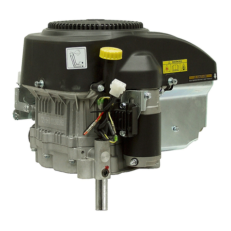
Toro GTS 120 User manual

2-CYCLE GTS 120 ENGINE SERVICE MANUAL
Table of Contents – Page 1 of 1
PREFACE
I. GENERAL INFORMATION
SAFETY INSTRUCTIONS
MAINTENANCE
MODEL AND SERIAL NUMBERS
TWO-CYCLE ENGINE THEORY AND OPERATION
CARBURETOR THEORY AND OPERATION
SPECIAL TOOLS LIST
II. MAINTENANCE
AIR CLEANER
SPARK PLUG
EXHAUST SYSTEM
DECARBONING CYLINDER HEAD
IGNITION TIMING (MODEL 47PZ2 ONLY)
IGNITION TIMING (DIAL INDICATOR)
CONTACT POINTS AND CONDENSER MODEL47PZ2 ONLY
IGNITION COIL
GOVERNOR
GOVERNOR OPERATION
FUEL TANK
CARBURETOR
STORAGE
III. TROUBLESHOOTING AND TEST PROCEDURES
PRELIMINARY TROUBLESHOOTING
ENGINE BRAKE AND IGNITION SWITCH
BBC APPLICATIONS
FUEL TANK
TESTING COMPRESSION
CRANKCASE
ENGINE TROUBLESHOOTING CHART
IV. ENGINE REMOVAL, DISASSEMBLY, ASSEMBLY AND REPAIR INSTRUCTIONS
ENGINE REMOVAL
ENGINE DISASSEMBLY AND REPAIR
RECOIL STARTER REPAIR
CARBURETOR REPAIR
ENGINE ASSEMBLY AND REPAIR
SERVICE DATA SPECIFICATIONS


PREFACE
This service manualwas written expressly forTORO Two-Cycle Rotary Mowers.
All
units with the modelnumber
47P22,47PD3,47PE4,
and
47PF5
engines
have beentaken intoconsideration.
The ToroCompany has made every
effort
tomakethis service manuala useful
tool for the serviceand maintenanceof your
TORO
Rotary Mower Engine.To
assure proper and effectiveperformance, you areurgedto readthis manual
carefully.
The purpose
of
this manualisto providethe Service Dealerwithworking
guidelinesof maintenance,troubleshooting,test,and overhaul procedures.
The ToroCompany reservesthe righttochangeproduct specifications or this
manualwithout notice.
The ToroCompany
Service
Department
COPYRIGHT ALL RIGHTS RESERVED
The
Toro
Company
1986
MINNEAPOLIS,
MN
55420
U.S.A.
i

TABLE
OF
CONTENTS
.
GENERAL INFORMATION
1-1
Safety Instructions
................................................................................
1-1
Modeland Serial Numbers
...................................
.,.
...................................
1-2
EngineSpecifications
.............................................................................
1-5
FastenerTorque Specifications
...................................................................
1-5
SpecialTools
......................................................................................
1-6
II.>
MAINTENANCE
..............................................................................
11-1
TOPIC PAGEE
1
....................................................................
Maintenance
.......................................................................................
1-2
Two-cycleEngineTheoryand Operation
..........................................................
1-2
CarburetorTheory andOperation
.................................................................
1-4
Air Cleaner
.......................................................................................
11-1
SparkPlug
.......................................................................................
11-1
Exhaust System
..................................................................................
11-1
DecarboningCylinder Head
......................................................................
11-2
IgnitionTiming(Model47PZ2 Only)
..............................................................
11-2
IgnitionTiming(DialIndicator)
11-3
Contact PointsandCondenser (Model47PZ2 Only)
..............................................
11-3
Ignition Coil (Model 47P22Only)
.................................................................
11-3
GovernorOperation
..............................................................................
11-5
....................................................................
Ignition Coil(Models47PD3.47PE4. 47PF5)
..................
..................................
11-4
Governor
..................................................................
......................
11-4
FuelTank
11-5
Carburetor
.......................................................................................
11-6
Storage
11-6
111
.
TROUBLESHOOTINGAND TEST PROCEDURES
111-1
Spark Intensity
..................................................................................
111-1
........................................................................................
...........................................................................................
..........................................
PreliminaryTroubleshooting
.....................................................................
111-1
Engine Brakeand IgnitionSwitch
................................................................
111-1
BBCApplications
................................................................................
111-2
FuelTank
.....................................................
..................................
111-2
TestingCompression
............................................................................
111-2
Crankcase
111-3
.......................................................................................
EngineTroubleshootingChart
...................................................................
111-4
IV
.
ENGINE REMOVAL, DISASSEMBLY, ASSEMBLY AND REPAIR INSTRUCTIONS
........
1v-1
Engine Disassembly and Repair
................................................................
1v-1
RecoilStarter Repair
............................................................................
1v-1
.................................................................................
Engine Removal
1v-1
CarburetorRepair
1v-2
ServiceData Specifications
......................................................................
1v-4
MaintenanceRecord
1v-6
MaintenanceRecord
1v-7
...............................................................................
............................................................................
............................................................................

SAFETY INSTRUCTIONS
Your rotary moweratthetimeof its manufacture,
meets the bladesafety requirementsof theCon-
sumer ProductSafety Commissions Safety Stan-
dard for Walk Behind Power Lawn Mowers.
A
representativesample was testedandverifiedby
an independent laboratory for compliance with
the B71.1-1980Specifications of the American
National Standards Institute. However, improper
use or maintenance by the operator orowner
can still result in injury. To reducethe potential
for injury follow these safetyinstructions.
6.Wear long pants and substantialshoes.
Do
notoperatethemowerwhilewearing
sandals, tennis shoes,sneakersorshorts.
Do not wear loose fitting clothingthat could
get caught in movingparts.
7.
If
long grass will becut, setthe height-of-cut
in the highest position. Aftermowing, rein-
spect the area and remove alldebris. Then
lower the height-of-cut and mow the grass
again.
8. Since gasoline ishighly flammable, handle it
carefully
This machine is equipped with abladebrake
whichisdesignedto stop the blade within
3
A. Use an approvedgasoline container.
B.
Donot
fill
thefuel tank when the engineis
seconds when the control lever is released.
Checkto besurethe control and brakefunction hot or running.
correctly before each useof the mower. Repair C. Do not smoke while handling gasoline.
D.
Fillthefuel tank outdoors and up to about
any defective or damaged safety components
beforeoperationiscommenced.To further one-half inchfromthe top of thetank, not
the filler neck.
reducethe possibility of injury, always stop the E. Wipeup any spilled gasoline.
enginebefore leaving the operator’s position.
While Operating
9. Cutting the grass with a rotary mower de-
Thissafetysymbolmeans
mands attention.Always maintain secure
WARNING
or
CAUTION
-
footing, balanceand control.
PERSONALSAFETY INSTRUCTION
-
10. Cut the grass during the daytimeor when
Read the instruction because
it
has to
there
is
adequate artificial light. Cutslopes
do
with safety. Failure to comply with
from side to side, but avoid slopeswhen the
theinstructionmayresult in personal
grass iswet.
If
possible, mowwhenthe grass
injury.
isdry for best results.
11.Keepface,hands and feetawayfromthe
BeforeOperating
mower housingand cutter blade while the
1.
Operateyour mower only after reading the engineis running. Stay behind the handle
Operators Manual.
A
replacement manualis
available by sending the completemodel 12. Duringoperation thegrass defector
or
com-
and serial number to:The Toro Company, plete baggingassemblymust beinstalledon
8111 Lyndale Avenue South, Minneapolis, themower.
Minnesota
55420.
Attn: Publications. 13. Stopthe engineand waitfor allmoving parts
2.
Never allow children to operate the mower to stop before removing the bag, bagging
or adults tooperate mower without assembly, oruncloggingthedischarge
properinstructions. chute.
If
the chute must be unclogged, pull
3. Becomefamiliar with the controls and know the hightension wire from the spark plugto
howto stop the enginequickly. preventthe possibility
of
accidental starting.
4.
Keep everyone,especiallychildren andpets, Use a stick to remove theobstruction.
away from the areaof operation. Remove 14.
If
a solid object is hit by the blade or
if
the
sticks,stones, wire and anyother debris that mower vibrates abnormally, stop theengine
might be picked up and thrownbythe blade. immediately. Disconnect the high tension
5.
TAMPERING WITH
OR
DEFEATING
A
wire from the spark plugtoprevent the
SAFETY DEVICE
OR
COMPONENT WHICH possibility of accidental starting.Then check
RESULTSINNONCONFORMANCE WITH
A
the mowerfor possible damage, bent blade,
an obstruction or loose parts.Repair the
-
SONAL INJURY. Eachtime before operating mower before using it again.
the mower, check for damage or abnormal 15. Stoptheenginebeforeadjustingthe
wear.
If
a safetydevice,shield,or decal
is
height-of-cut.
defective ordamaged, repair or replace it 16.
If
a gravel driveway, road orpathmust be
before operation iscommenced. crossed, stop the engine
so
loose sand and
until the engine andall moving parts stop.
SAFETY STANDARD, MAY RESULTINPER-
1-1

rocksare not thrown.
17.
Beforeleavingthe operator’sposition behind
the handle, stop the engine and wait for all
movingparts to stop. Do not walk infront of
the mower while the engine isrunning. Dis-
connectthe hightension wire from thespark
plug
if
the mower will be unattended.
18.
Do
nottouch any part oftheenginewhile it is
runningor shortly after it is stoppedbecause
the enginewillbe hot enoughtocausea
burn.
Muffler
is
extremely hot.Keep
children and pets away.
I
MAINTENANCE
19.
Beforethemoweris serviced oradjusted,
stopthe engine andremovethe key fromthe
switch. Disconnectthe high tension wire from
thespark plug toprevent the possibility of
accidental starting.
20.
Toassurethe mower is in safe operating
condition, keep all nuts, bolts andscrews
tight. Assurethe blade capscrew istightened
to the propertorque.
21.
If
major repairs are ever needed or
if
assis-
tanceis desired, contact an Authorized
TORO Service Dealer.
22.
If
the mower must be tipped when it is
servicedor adjusted,drain thegasoline from
the fuel tank.
23.
If
a guard,safety device orsafety decalis
damaged, replace the defective part(s) be-
fore operatingthe mower.
24.
To reduce potential fire hazards, assurethe
mower is free
of
excessive grease,grass,
leaves and accumulationsof dirt.
25.
The grass bag must always beingood con-
dition; therefore, check itbeforeeach useto
assure the bag is not torn
or
deteriorated.
Always replace a defective grass bag.
26.
Allow the engine to cool before storing the
mowerinany enclosure suchas a garageor
storage shed.
Do
not store the mower near
any open flameorwhere gasoline fumes
may be ignited by a spark.
27.
Do not overspeedthe enginebychanging
the governorsettings. Recommended speed
of the engine is
3000
rpm. To assure safety
andaccuracy, have anAuthorized TORO
Service Dealercheck the enginespeed with
atachometer.
28.
At the time of manufacturethe mower con-
formed to the safety standards in effect for
rotary mowers. To assure optimum perfor-
mance and continuedsafety certification of
the mower, use genuineTORO replacement
parts and accessories. Replacement parts
andaccessories madebyother manufac-
turers may result in nonconformance with
the safety standards.
MODEL AND SERIAL NUMBERS
The TOROTwo-cycleRotary Mowerhastwosets
of identification numbers.Thereis a model and
serial numberto identify the engine and a model
and serial number to identify the chassis. The
engine identification numbers are stamped into
the blower housing behindthe air cleaner.Model
47PF5 engines built for
1986
have the engine
identification numbersstamped inthe blower
housingabovethespark plug. Enginemodels
47PE4and 47PF5 haveserial numbersthat start
withthenumber
1,
2
or
3.The
number
1
indicates
a
zone start application. The number
2
indicates
BBC applicationandthenumber
3
indicates
commercial application.
The chassisidentification numbersarelocatedon
a decal on the back
of
themower housing, between
the rear wheels.
In any correspondence concerning the mower,
supply the model and serial numbers to assure
thatthecorrectinformationand replacementparts
are obtained. Genuine TORO replacement parts
may beordered throughyour
local
TORO Autho-
rizedService Dealer.
TWO-CYCLE ENGINE THEORY AND
OPERATION
Theory
Two-cycleengines have special advantages
which make their usemore practical in certain
applications. Two-cycle engines arelightweight
with an excellent power to weightratio and can
beoperated in any position. They are also
notably easy to maintainand service becauseof
their uncomplicateddesign.
The TOROTwo-cycleEngine usedontheTORO
Rotary Mowers is a third-port, loop scavenged
design. This design name describesthe path of
thefuel
/
air mixtureintothe crankcase and com-
bustion chamber, and the exhausting of spent
gases.
Ina loop-scavengeengine, a high pressurearea
is created in the crankcase by the downward
movement of the piston. Pressurizedfuel-air
mixture rushesinto the combustionchamber
through the intake ports and is directed toward
the cylinder head.Thisfresh mixturethenstrikes
the cylinder head and loops down forcingburnt
gases in the combustion chamber out through
1-2

the exhaust ports. The third port design engine
has the carburetor mounted on the side of the
cylinder. Thepassage from the carburetor into
the crankcase is called the third port.
All
ports
within the engine areopened and closedby the
piston skirt as the piston movesupand down
within the cylinder.
Operation
The piston closes all engine ports as it moves
toward thecombustion chamber(Figure1-1). The
movingpistoncreates ahighpressureinthecom-
bustion chamber and a partial vacuum in the
crankcase.
Intake Ports Closed
Co
Figure1-1
At
apointslightlybeforetopdead center(BTDC) of
thepistontravel, from the plug ignitesthe
fuel air mixture(Figure1-2).Also, atthis time, the
third portopensallowingthefreshfuel/air mixture
torush into thecrankcase to equalizethe partial
vacuum.
Intake Ports Closed
\
Figure 1-2
When the fuel is ignited by the sparkplug, the
expanding gases fromtheburningfuelin thecom-
bustionchamberforcethepistondownthecylinder,
closing thethird-portandincreasingthe pressure
inthe
crankcase.At
apointapproachingthebottom
ofthestroke,theexhaustportopensand theburnt
1-3
gases beginto beexpelled fromthe combustion
chamber(Figure1-3).
__-
--l_____m_
Intake Ports Closed
Exhaust Port
I
Third
PortClosed
~
Figure
1-3
At a point of piston travel slightly before bottom
dead center (BBDC)
the
fueltransfer ports,on the
sides of the cylinder walls, are uncovered and
thecompressedfuel/air mixtureinthe crankcase
-is allowed to enter the combustionchamber
wherethey help expel theburnt gases and
charge the chamber for the followingpiston
stroke (Figure1-4).
Intake Ports
Open
Exhaust
Change
__-__
Figure 1-4
CARBURETOR THEORY AND OPERATION
Theory
The carburetor receives fuel from the tank and
mixes
it
with air in therightproportionsto
provide a highly combustible mixture to the
engine.
As the piston moves up on the compression
stroke a partial vacuum is created within the
engine crankcase, causingthe greater atmos-
phericpressuretoforceairtoflowthroughthe
carburetor into the cylinder. The velocity of the
air increases as it flows through the carburetor
venturi and the air pressure is reducedat this
pointto less thanatmospheric pressure. The
differences of pressure in the venturi of the

carburetor causes atmospheric pressureto push
rawfuelfromthe
float
bowlintotheair
stream,where
it breaks up into a fine spray, or becomes atomized,
andmixes withthe airstream (Figure
1-5).
Float
Bowl
ToEngine
Figure
1-5
Operation
When startingtheengine,an extra richmixtureis
required.The chokeplateisclosedbytheopera-
tor to providean approximate
8:1
ratio of fuel to
air for this rich mixture. Closing the choke plate
further reducesthe air pressurearea inthe
venturi to increase the fuel drawn into the car-
buretor bore. Inthis condition fuel is drawnfrom
the float bowl through the pilot system ports as
well as the main discharge tube to achieve the
proper starting mixture(Figure
1-6).
Pilot
Jet
Pilot System
Pilot Air Fitting
COLD START
Figure
1-6
Fuelatomization becomes moreefficient,due to
heat, oncetheengine has reachednormal
operating temperature.
As
a result, theengine
doesnotrequirethe rich mixtureit did for
starting and the choke plate must be moved
to
the open position. The engine speed is now
regulated by the throttleplate.In no load condi-
tions a small portion of the fuel may be drawn
from the main discharge tube, however the pri-
mary fuel supply is drawn from the pilot circuit.
1-4
Air passingthrough the pilot jetfrom the pilotair
fitting draws fuel outof the pilot jet orificefrom
thefloatbowl.Thisfuelpre-mixeswiththe
incoming air, thenisdischargedintothe car-
buretor bore where the fuel becomes atomized
(Figure
1-7).
NO
LOAD
Figure
1-7
As
the throttle plate isopened to compensate for
loadsthe engine is being placedunder,the main
discharge tubebecomes the mainsourceof fuel.
Opening the throttle plate increases the flowof
air through the venturi andstrengthens the low
pressure area at the main discharge tube. Fuel
discharge increases at the main dischargetube
as
it
decreasesfrom thepilot system. Air
is
drawn from the air correction jet through holes
alongthe lengthof the maindischargetube.This
pre-mixes air with the fuel before it enters the
carburetor bore for more efficient atomizing of
:hefuel (Figure
1-8).
/pilot
System
Float
Bowl
UNDER LOAD
Figure
1-8

ENGINE SPECIFICATIONS
~---
Model
47P22
Type 2cycle, single cylinder piston
ported, aircooled
Rotation(viewedfrom output end) Counter-clockwise
Displacement 121cc (7.38cu.in)
~-
Bore 58 mm(2.28 in)
Stroke 46 mm(1.81in)
Crankshaft 24.9mm(.98in) forged steel
RatedOutput
3.5
Hp
@
3600RPM
Torque.73kg-m(5.28 ft-lb)
@
3000
RPM
CompressionRatio 6:1
Compression
Gas-OilRatio
50:
1
Gasoline UnleadedRegular
TTO
Oil 2cycle oil
FuelTank Capacity
Air Cleaner
Carburetor Mikuni
BV-15std.
mainjet #80
HighAltitude Jet
Governor MechanicalFlyweight
8.4kps/cm2 20psi)to
10.5 kps/cm (1
50
psi)
1.89
I
(2 qt)
Two stagefoam element
#77.5
--
-~
SparkArrester Muffler Optional(PN 81-0200)
47PD3
#76.3
#72.5
Starter Recoilonly
~-
SparkPlugNGK-BPMR6A NGK-
BPMR4A
IgnitionTiming 22" 2" BTDC
IgnitionTiming, PistonPosition 1.76-2.51mm (.069-.099in) BTDC
~-
Contact PointGap.35 mm (.014in)
IgnitionCoil AirGap .38-.50mm (.015-.020in)
Float Height Setting (BlackFloat)
*
N/A 11/16"
*The blackfloat may beusedonthese enginesas a replacement. Part number
81-0970.
.
N/A
*
N/A
FASTENER TORQUE SPECIFICATIONS
Adapter Plate HousingCapscrews(3/8-16UNC) 2.9-4.6 Kg-m(21
-33
ft-lb)
BladeCapscrew 6.2-8.3 Kg-m (45-60ft-lb)
FlywheelNut (M 10) 4.0-5.0 Kg-m(29-36ft-lb)
Muffler Nuts(M 8) 90-120Kg-Cm (100-140in-lb)
Air CleanerLock Nuts(M6) 60-90 Kg-Cm(70-1
05
in-lb)
Adapter Plate EngineCapscrews (M8) 90-120Kg-Cm (100-140in-lb)
Crankcase Capscrews (M 6) 80-95 Kg-Cm(70-110in-lb)
Shroud
&
MufflerCapscrews (M6) 40-70Kg-Cm(45-80in-lb)
Ignition Switch Mounting Capscrew(M6) 80-115Kg-Cm(90-1
30
in-lb)
Air CleanerMountingCapscrew (M
5)
17-26Kg-Cm(20-30in-lb)
RecoilStarterCupCapscrews(M6) 80-95Kg-Cm(70-110in-lb)
RecoilMountingCapscrews(M 6) 35-65Kg-Cm(40-75 in-lb)
RecoilCenter Capscrew(use thread lock compound) 80-95Kg-Cm(70-110in-lb)
Spark Plug(M 14) 70-1
05
Kg-Cm(80-120in-lb)
Throttle Plate Capscrews (M6) 80-95 Kg-Cm(70-110in-lb)
.-
.
-..-
__-
1-5

SPECIAL TOOLS LIST
ITEM
1
2
3
4
5
6
7
8.
9
10
11
12
13
14
15
16
17
18
19
20
21
22
DESCRIPTION
PART
NO.
Flywheel Puller..
..................................
41-7650
StarterCupWrench
................................
45-1390
SparkTester
......................................
41-7890
Continuity Light
...................................
36-4050
Tachometer..
..
.................................
42-2730
Ohmmeter(Multimeter).
Feeler Gauges
Micrometer.
Spark PlugGappingTool
CompressionGauge..
TimingTester..
....................................
41-7900
...........................
....................................
.......................................
..........................
.............................
Threebond#1104(Loctite#515).
.................
505-80
Loctite
#242
(Threebond#1342).
.................
505-76
Timing Dial Indicator..
Dial Indicator..
Cylinder GaugeSet..
Spark PlugSocket..
CoilGauge
.38-.50mm
(.015-.020 in)
Torque Wrench(ft-lb)
Torque Wrench(in-lb).
Magnetic
“V”
Blocks..
Dial IndicatorStand
.............................
....................................
..............................
...............................
...............
..............................
.............................
.............................
...............................

CAUTION: To reduce poten-
tial accidents, never perform
an adjustment or maintenance proce-
dure while the engine is running. Pull
the high tension wire
off
the spark plug
to prevent an accidental start.
AIR
CLEANER
The air cleaner must be maintained properly to
ensure foreign materials cannot damage the
engine
or
foulthecarburetor. The air cleaner
element must be cleanedafterevery
50
hoursof
engine operation,or morefrequently
if
theengine
isoperated industy
or
dirty conditions.
Lift the cover tabs securing the air cleaner cover
tothe housingandremovethecover(Figure2-1).
Clean the inside
of
the cover and housing if it
is
dirty.
Figure2-1
If the air cleaner element is dirty remove it from
the housing
for
cleaning.
DO
NOT ALLOW DIRT
TO ENTER BEHIND THE ELEMENTOR ENGINE
DAMAGE WILL RESULT. Washthe element in a
solution of liquid detergent and water. Squeeze
the element to remove the dirt. Do not twist the
element or the elementmaytear.Press the
element in adryraguntil itis completelydry.
Saturate the element with approximately five
teaspoonsof SAE
30
oil andsqueezetodistribute
the oilthoroughly.
Theelementmust be dampened with oil to
function properly.Replacetheelementandinstall
the cover. Assure that the cover snaps in place
and isseatedsecurelyontheaircleaner housing.
IMPORTANT: DO NOT OPERATE THE ENGINE
WITHOUTAN
AIR
CLEANERELEMENTOR
EXTREME ENGINE WEAR AND DAMAGE WILL
RESULT.
SPARK PLUG
Many timesan inspectionof the spark plug can
determinewhethertheengine isfunctioning
properly. A spark plugwhichisfunctioning
normallywill show slightelectrode wear with
brown
or
greyishtan deposits. Oilfouledand
black carbon fouled plugsare caused by a rich
carburetor mixture, weak spark, or improper
gasoline to oil mixture. Excessivelyworn elec-
trodes ora blisteredinsulator indicatespark plug
overheating. Look for incorrectignition timing,
cooling fins clogged withdebris,improper gaso-
line to oil mixtureand dirty carburetor, any of
which may cause this trouble.
IMPORTANT:
A
CRACKED,FOULED
OR
DIRTY
SPARKPLUGMUSTBEREPLACED.DONOT
TRODES.GRITMAYEVENTUALLYRELEASE
AGE.
The recommended sparkplusisanNGK-BPMRGA
or
NGK-BPMR4A (Champion RCJ8Y). See Page
1-5.
Theairgap betweentheelectrodes should beset
at
.8
mm
(.032in)
(Figure2-2). Since the air gap
increases gradually through use, the spark plug
should beremovedafterevery25 hours of opera-
tiontocheck itscondition.Cleanthe area around
the spark plug to prevent foreign materialfrom
falling into thecylinder.Install thespark plug with
the metal gasket and tighten to 70-105Kg-Cm
(80-120 in-lb).
SAND BLAST, SCRAPE OR CLEAN
THE
ELEC-
FROMTHEPLUGAND CAUSEENGINE DAM-
(.032
in)
EXHAUST SYSTEM
Oneimportant part of the maintenance for all
two-cycleengines is thecleaning
or
de-carboning
of the exhaustsystem.This is donetoassure the
unobstructed flowof exhaust gases and carbon
particles from the combustion chamber.
A
se-
verelycarbonedmuffler,spark arresterscreen or
exhaust portwillcausepoorstartingand
low
poweroutput.To de-carbon theexhaust system,
11-1

removethe muffler from the engine by removing theloosecarbon from the muffler usingcom-
the tworetainingnutsandthe throughbolt(Figure pressed air.Installthe mufflerusing a new gasket
2-3). and attach it with proper fasteners tightened to
the correcttorque. See page
1-5.
DECARBONING CYLINDER HEAD
Ifthe exhaust ports andmufflershow signs ofex-
cessivecarbon buildup,
it
may be necessary to
de-carbonthecylinderhead.Toaccomplishthisthe
entireengine must be disassembled to allow
access into the combustion chamber.(See Dis-
assembly Instructions PageIV-1.)Remove the
carbon deposits fromthe piston and thecylinder
chamber usinga wooden stick.TAKE CARE NOT
TOSCRATCHTHEPISTON
OR
CYLINDER
CHAMBER AND DO NOT USE A METAL TOOL TO
REMOVE THE DEPOSITS.
Figure2-3
Check thecylinder exhaust port.
If
necessary,
remove the carbondeposits from the port using
a woodenstick.Also clean thesmall hole nextto
theexhaust port.Thisholeactsas a compression
relief to lessen theforcerequiredto start the
engine.
If
plugged, the recoilstarter will be hard
to pull(Figure2-4).
POSITS, ROTATE THE CRANKSHAFT TO
CLOSETHEEXHAUSTPORTWITHTHEPIS-
TON.THISWILLPREVENTLOOSECARBON
DEPOSITSFROMFALLINGINTOTHECYLIN-
DER.TAKECARENOTTOSCRATCHTHE
PISTON AND DO NOT USE
A
METAL TOOLTO
REMOVE THE DEPOSITS.
IMPORTANT:WHENREMOVINGCARBONDE-
\
Beforeinstallingthe mufflercheckfor cracksand
leaks. Inspect theinletand outlet for carbon
buildup. Remove excessivedepositswith a
scraping tool and soak the muffler in solvent to
remove wet oil deposits. Allow to air dry or dry
with compressedair.Remove the muffler heat
shieldand tap the muffler bodywith a plastic
hammer
to
loosen the carbondeposits. Blow all
11-2
IGNITION
TIMING
(MODEL
47P22
ONLY)
To check the timing
it
isnecessaryto remove the
aircleaner toview theflywheel. (See Disassembly
Instructions.)The flywheel has a group of three
raised marks on itsouter edge. The center mark
correspondsto BTDCandtheothersrepresent
thetoleranceof plusor minus2O.Connect onelead
ofthe timing testertotheengine frame (ground).
(A
timing testermustbeused. An Ohmmeter orconti-
nuitylight will not indicate the positionof thecon-
tact points.) Disconnect the wire at the ignition
switch under the fueltank and connectthe other
testerleadto this wire(Figure2-5).Turn theengine
crankshaftinitsnormalrotation,counter-clockwise
as viewed fromthe outputend. Thecontact points
should open, asindicatedbythetimingtester, when
the pointer on thecrankcasehousingpointsto the
Centerofthe
three
marks on theflywheelcasting.
If
thetiming iswrong theflywheelmustberemoved
andthe contact pointsre-gappedor replaced.
Models 47PD3, 47PE4 and 47PF5 usesolid state
ignition systems and have their timing fixed at
BTDC.
Figure2-4
Figure
2-5

IGNITION TIMING(DIAL INDICATOR)
The ignitiontiming may bemoreaccurately
checkedusinga dial indicator. Removethe spark
plugwire and sparkplugandinsertthedialindica-
tor into the spark plug hole. Rotatetheengine
crankshaftuntilthedialindicatorregistersthepis-
tonattopdeadcenterand“zero”thedial. Connect
one leadof atiming tester to the engineframe.
(A
timingtester must beused.An Ohmmeteror con-
tinuity lightwill notindicatethepositionofthe
con-
tactpoints.) Disconnectthe wire at the ignition
switch under the fuel tank and connectthe other
tester leadto thiswire (Figure 2-6). Slowlyrotate
the crankshaft clockwise, as viewed fromthe out-
putend,untilthe tester signalsthe contact points
are opening.
If
thetestersignals between1.76 mm
(.069
in) and 2.51 mm
(.099
in)of piston travel, as
read on the dial indicator, the engine is properly
timed. Ifthetiming iswrong theflywheel must be
removed andthe contact points re-gapped.
Figure2-6
CONTACT POINTSAND CONDENSER
MODEL47P22ONLY
The contact points and condenser dowear out
through use and their performance level is
affected by dust, moisture andcorrosion. Inspec-
tion of these componentsrequiresremovalof the
flywheel.
(See Disassembly Instructions.) With theflywheel
removed, inspect forwearofthecam follower
and burningor pitting of the contact points.The
surfaceof the contact pointsshouldhaveagrey,
frosted appearance
if
wearing normally.
If
the
contact points are cratered orhave surface
buildupthey should becleanedor replaced.The
contacts can be cleaned with an electrical
sol-
vent andcontact pointsandpaper. Ensure thatall
dust and dirt
is
removed after sanding. Cratering
of the points indicates the condenser may be
faulty.Verify the condition ofthe condenser
through tests with anignition analyzer.
If
an
analyzer isnot available the condenser must be
consideredfaulty and should
be
replaced.When
installing newor reconditioned contact points
ensure thatthewiring isroutedthroughthechannel
in the crankcase housing and under the ignition
coil.FAILURETOROUTETHEWIRESPROPERLY
WHEEL
AND
CAUSE
A
SHORT CIRCUIT. Adjust
thecontactpointsto
.35
mm(.014 in) air gap,using
a feeler gauge, with the cam follower onthe high
pointof thetimingcam (Figure
2-7).
Checkthetim-
ing using either method previously described. It
may be necessary to readjust the contact point
gaptoobtain thetiming specification.
MAY ALLOW THE WIRING TO CONTACT THE FLY-
Contact Point
Assembly
Condenser
I
Cam
Follower
Figure
2-7
IGNITION COIL
Whenever the flywheel is exposed the ignition
coilconditionand air gapshouldbechecked.
Inspectthe ignitioncoil
for
acrackedcasing, loose
laminations,damagedwires and overheating.The
ignition coil air gap is
.38-50
mm(.015-.020 in).
A
non-metallicflexible gauge suchasshownin the
SpecialTools Section should beused. Toadjust,
rotate the flywheel magnetsaway from the igni-
tion coiland loosenthe two ignition coil retaining
capscrews. Insert the gaugebetweenthe coil
laminationsandtheflywheel (Figure2-8).Tighten
the retaining capscrewsto hold the adjustment.
Figure
2-8
11-3

The ignition coilcontains two separate windings
inside the coil casing (Figure 2-9). Use an Ohm-
meterto check theresistancelevelsof each wind-
ing. Tocheck theprimary winding,disconnectthe
ignitionswitchwire andconnectthe positivelead
of theOhmmeterto the ignition coillead.Connect
thenegative leadtotheengineframe (ground).
The
primary winding resistance is ohms
(Rxl
scale). To check the secondary winding, disconnect
the high tension wire at the spark plug.Connect
the positiveleadof theOhmmetertothe highten-
sionwire.Connectthe negativeleadtotheengine
frame (ground).The secondary coil resistance
should be 5800-7940ohms
(Rxl
000
scale). The
ignition coil must be replaced
if
the resistance
levels areincorrect.
Ignition Switch Wire High Tension Wire
\
ohms
Primary
Coil
Secondary
Coil
(R
x
1000
scale)
5800-7940
ohms
Ground
Model
47P22
Figure 2-9
The ignition coilused on models 47PD3, 47PE4,
and 47PF5consists of the main coil,hightension
wire andignition killwire (See Figure2-1
0).
Testingof thecoilmaybecompletedwitha
Graham
Lee ignition tester model number31-SMXH.In-
structionsfor testing are includedwith the tester.
High Tension
Wi
Figure 2-1
0
GOVERNOR
The governor linkage is factory preset to regu-
latetheenginespeed at
3000
150 RPM.
Check theadjustment of the governor
if
the
engine is suspectedof improperspeed. To gain
access to the governor linkage removal of the
air cleaner is recommended. (See Disassembly
Instructions.) Beforeadjusting the governor,
inspect the control linkage forbent, broken and
worn parts. Loosen the governorarm clamping
bolt and use ascrewdriver to spreadthe gover-
nor arm clamp (Figure 2-11).
Figure 2-11
Adjust the governor by holding the governor
lever tothe rightwhile turning the governorshaft
to the right. Hold theadjustment and tighten the
clamp bolt(Figure 2-12).
Figure 2-1
2
Connect the return spring to the center hole in
the governor spring bracket.The centerhole
should govern the engine speed at the recom-
mended
3000
RPM.The top hole will raise the
engine speed 150
RPM
and the bottomhole will
lower the engine speed 150RPM. Engine speed
can beverified using a tachometersuch aslisted
in theSpecial Tools Section. (Seepage
1-6).
II
-4

GOVERNOR
OPERATION
(Referto Figure 2-13.) Asload on the enginein-
creasestheenginespeedwillstartto
decrease.As
theengineslows downthe centrifugalforceofthe
flyweights (1) will decrease. The governor return
spring(4)willcausethegovernorcollar(2)tomove
indirection(A).
The
governorarm(3)willalso move
indirection(A)causingthethrottleto
open
untilthe
centrifugal force
of
the flyweights are in balance
withthegovernor returnspring.As the loadonthe
enginedecreasesthe enginewill speed upcaus-
ingtheflyweightstomove outforcingthegovernor
collarindirection(B).
The
collarwillact againstthe
governor arm moving it indirection (B) and also
moving the throttle in direction
(B).
The engine
speedwill drop until onceagainthe flyweight and
returnspringare inbalance (Figure 2-13).
1
Figure2-1
3
Models 47PD3,47PE4 and 47PF5are equipped
with variable throttles.The linkageisdescribedin
(Figure 2-14).
A
mountingboss wasadded tothe
castingof the enginetoaccommodatethe throttle
linkage assembly. The boss does not exist on
model47PZ2enginesthereforethevariablethrot-
tle linkagewill not retrofit. Model47PF5 engines
willincludeaweldstud onthegovernorlinkagefor
ease of reassembly (See Figure 2-1
5).
Governor
Arm
Governor
Spring
Figure2-14
Figure2-1
5
FUEL
TANK
!
CAUTION:
Thegasolinein
thefueltankisexplosive.
Alwaysdrain or
fill
tankoutdoors,
awayfromfireandflame.
Do
not
smoke when fuel vapors are present.
Fortheengineandcarburetortofunction properly
the fuel supply mustbeclean. Stale,dirty and im-
properlymixedfuelwillcausestartingandrunning
difficulties.To assure a clean fuel supply the fuel
tank may be removedandflushed with fresh fuel.
(See Disassembly Instruction.)
A
non-replaceable
sinteredbronzefuelfilter is insetintothefuel tank
outlet.Insome cases,the filter can be cleanedby
backflushingwith solvent or byblowinglow pres-
sure compressed air through the fitting on the
bottomof thefuel tank. Commercial engines have
areplaceable inlinefuel filterlocatedbetween the
fueltank
andcarburetor.The
replacementfuelfilter
isToroPart Number56-6360(Figure2-16).Period-
icallyinspectthevent in thefueltankcap. Remove
anyforeignmaterialswhichmayplugthe
vent.The
gasket inside the capmay be removedto permit
further cleaningof the vent area.
Fuel
Cap
(molded intolank).
Fuel
Filter
Inline
FuelFilter
Part
No.
56-6360
Figure2-16
11-5

CARBURETOR
The non-adjustable carburetorhas a numberof
small orifices which control the flowof fuel and
air to obtain the proper combustable mixtures.
If
stale or dirty fuelentersthe carburetor, deposits
canformcausing adverse changestothis
cornbustable mixture.To clean the carburetor it
must first be removedanddisassembled.(See
DisassemblyInstructions.)Soak allmetal partsin
carburetor cleaner to remove deposits. THE
BOWL SEAL, FLOAT
AND
NEEDLEVALVE
TORCLEANER
OR
DAMAGEMAYRESULT.
Replace any damaged or questionable compo-
nents before reassembly (Figure2-1 7).
SHOULDNOTBECLEANEDWITHCARBURE-
PilotJet
Float Pivot Pin Needle Valve
Bowl
Seal
Engine Model47P22
Bowl
Carburetor
Standard Main Jet
#80
Toro
Part
No.
81-1040
Optional High-altitude
Main
Jet
#77.5
Tor0
Part
No.
81 -1
050
Figure2-17
Carburetors used onmodels 47PD3,47PE4 and
47PF5 (seeFigure2-18), use a metalchokeshaft
with a plastic bushing,an atmospheric venttube
and analcohol resistantfloat.The floats used on
47PZ2 carburetorsshould bereplacedwitha 81-
0970
float.
This
float is black
and
isequippedwitha
metalhinge.Correctfloatheightis17.5 mm(11/16
in). The standard mainjet is a number 76.3 (part
number 81-1940). There is a lean, number 72.5,
mainjet (part number81-2340)availablefor high
altitudeconditions.
The standard mainjet on 47PZ2 carburetorsisa
number
80
(partnumber81-1 040) withahigh alti-
tude(77.5 jet part number 81-1
050)
option.
Models47PD3,47PE4and47PF5arealso
equipped with aheat deflector and insulator as
showninFigure2-18).Model 47PZ2wasbuiltwith-
out insulatorsor heat deflectors.This model may
be fitted witha heat shield kitnumber81 -221
0
to
prevent hot restart problems.
47PD3,47PE4,47PF5
Engine Model
Carburetor
Standard MainJet
Toro
Part
No.
81-1940
High Altitude Main Jet
Toro
Part
No.
81-2340
Figure
2-
18
STORAGE
Drainthe gasoline
from
the
fuel
tank.
Afterthegas-
olineisdrained,startthe engine andlet
it
rununtil
all fuelisexpended. Movethe recoilstartera num-
berof timestoassure
all
fuelisexpended.
All
gas-
olinemust beremovedtoprevent gumlikevarnish
deposits from formingin the fuelsystem. Pullthe
hightensionwire
off
thespark plug. Cleanthearea
around the plug toprevent dirt from entering the
cylinder when the plug isremoved. Removethe
plug from the cylinder head and pour two tea-
spoons of two-cycle oil into thespark plug hole.
Pull the recoil starter handle slowly to distribute
the oilinsideof thecylinder.Install thespark plug
andtightentothe recommendedtorque.DO NOT
INSTALLTHE HIGH TENSIONWIRE
ON
THE
SPARK PLUG.Pullthe recoilstarter slowly untila
positiveresistanceisfelt. This willensurethecom-
bustionchamberissealedby
the
pistontoprevent
any damagewhich might be causedby the envi-
ronment. Cleanthedirt andchafffromthe outside
of
thecylinder,cylinderheadfinsandblower hous-
ing. Theair cleaner assemblyshould beserviced
as mentioned earlier in thissection. For lawn
mower storageinstructionsrefertothe Operators
Manual.

111.
TROUBLESHOOTING AND TEST PROCEDURES
Generally all gasoline-powered products require
some form of service
or
repair during their life-
time. The amount of time and expense involved
in repairing a productcan be greatly impacted
by the amount of time required toinitially deter-
mine the cause of the difficulty. Therefore, it is
recommendedto make thesepreliminarychecks
beforeproceeding tosecondarytroubleshooting
procedures.
PRELIMINARY TROUBLESHOOTING
Ignition System
1. Check the ignition switch and wiring
2.
Ensure the sparkplug isthe correct type
3.
Check thespark plug for the correct gap,
damagedandexcessively carboned
or
burnt
electrodes
4.
Check the spark intensity.
1.
Check the choke position and controls
2.
Check the throttle (if
so
equipped)andgover-
3. Ensurethefuel is fresh, clean and of the
4.
Check the fuel filter.
1. Check for housing and element damage
2.
Check for dirty element
3.
Check for toomuch
or
toolittleoilin the
Fuel System
nor mechanism
proper gas-oil mixture
Air Cleaner
element
Compression
page
111-2)
1.
Check the cylinder compression. (Referto
Crankcase
1. Ensure the crankcase is sealed. (Refer to
page
I11-3)
Spark Intensity
The ignition system canbechecked
for
spark in-
tensity usingthesparktester listed in theSpecial
ToolsSection of this manual (Figure
3-1).
Figure
3-1
1. Pull
off
thespark plugconnector andremove
the sparkplug.
2.
Inspect the spark plug for wear, carbon
deposits and damage.(SeeMaintenance
Section) Replace theplug
if
damaged, burnt,
or
fouled.
3. Check for the correct spark plug gap and
adjust,
if
necessary, to
.8
mm
(.032
in)by
bending the outer electrode. Do not pry
against the inner electrode
or
the insulator
may bedamaged.
4.
Attach the spark tester as shown and verify
the tester gapis set at
4.2
mm (.166 in).
5.
Pull the starter and observeforspark. THE
SPARKMAYBEDIFFICULTTOSEE
IN
WELL LIGHTEDAREAS.
A
CAUTION:
Do
nottestfor
sparkwheregasolinehas
been spilledor inflammable vapors may
exist.
A
fire could result.
6.
If
no spark is viewed, refer tothe trouble-
shootingchart. (Page
111-4)
ENGINE
BRAKE
AND IGNITION SWITCH
As a safetymeasurethe engine is designed to
stop within three seconds after the control bar is
released. Releaseof the control bar grounds the
magneto through the ignition switch to prevent
ignitionandallows the spring activated brake
pad to engage the flywheel.
The engine brake andignitionswitch are con-
trolled by one common control cable activated
bythe control bar on the mower handle. To start
the engine the controlbar is raised and held
againstthe handle. This pulls the brake pad
away from the flywheel and simultaneously de-
pressesthe plunger on theignition switch.
THE ENGiNEBRAKESYSTEMSHOULD
BE
TION
OR
INJURY MAY RESULT.To troubleshoot
the engine brakeand ignition switch:
1. Removethe fuel tank for ease of inspection.
(See DisassemblyInstructions page IV-1).
2.
Ensure that the brakespring forcesthe brake
pad against the flywheel when the control
bar is inthe ‘STOP”positionandthat thepad
clearstheflywheel when the control bar is in
the ‘START” position.
MAINTAINED
IN
PROPERWORKINGCONDI-
111-1

3.
4.
Disconnect
the
wire leadingto the ignition
switch and connect acontinuity testertothe
switchwireandengine frame(Figure
3-2)
with
the control barin the
“STOP”
position there
should becontinuity through theswitch.With
the controlbar in the“START” position,there
should be
NO
continuitythrough the switch.
Adjust thecable
or
replacetheswitch which-
ever is necessary to assure that the switch
and brake assemblyarefunctioningproperly.
Figure
3-2
BBC
APPLICATIONS
EnginesequippedwithaBladeBrake Clutch(BBC)
mechanism, Models 47PD3,47PE4 and 47PF5
with serial numbers that start with
2.....,
are fitted
with an ignition killswitch that ismounted on the
throttle linkage. (SeeFigure
3-3.)
The ignitionwire
isconnectedto the killswitch terminal.
When the lift bailisreleasedthe BBC mechanism
willstop the blade andleavethe enginerunning.To
stoptheenginethe throttlecontrolisbroughttothe
stop positionwhich will bring thegovernor spring
lever in contact with the killswitch grounding the
ignitionand stoppingthe engine.
I
I
Spring
Lever
Kill
Switch
Bracket
Figure
3-3
FUEL TANK
If
the enginestalls or will notstartthere may bea
fuelrestriction orblockage.The fuelcap con-
tains aventwhich,
if
plugged, will prevent fuel
from entering the carburetor.
1.
2.
3.
Remove the fuel cap and inspect the vent.
Clean
if
necessary.
Visually inspect the bottom of the fuel tank
for dirt or other contaminants.
If
dirt, water
or
other contaminantsare
present the tank shouldbe flushed with a
smallamount of freshfuel. Thisismosteasily
accomplished whenthefueltank isremoved.
(See DisassemblyInstructionspage
IV-1).
a
CAUTION: The gasoline in the
fueltank
is
explosive.Always
drain
or
fill
tank outdoors, away from fire
andflame.
Do
notsmokewhenfuel
vapors are present.
4. Toensurethe fuel filter isnotplugged, remove
the fuel lines and check the fuel filterfor ease
offuelflow.Insomeinstances,thefiltermaybe
cleaned by back-flushingwith solvent or low
pressure compressed air.
NOTE:
The bronzesintered filter in the fueltank is
not replaceable,howeverthe remote mountedin-
line fuel filter found oncommercial engines maybe
replaced using Toro Part Number 56-6360. See
Figure
2-1
6.
TESTING COMPRESSION
A
compression test of theenginecanprovide
vital information on thegeneral condition of the
workingpartswithinthe engine. This test will
indicate a worncylinder, piston,
or
rings, and
generally determinewhether theengineisre-
pairable
or
if
it should bereplaced.
1.
Remove the spark plug and install a com-
pressiongaugeintothesparkplughole
(Figure3-4).
Figure3-4
111-2

2.
Pull the starter rope rapidlyseveral times
until the compression reading on the gauge
stabilizes.
3.
If
thecompression readingisbelow
6.5
kps-cm2
(92
psi),
cylinder,
pistonorringdamageshould
besuspected.
A
new engine should have
8.4
kps-cm2
(1
20
psi)
1
0.5
kps-cm2
(1
50
psi).
An engine withlow compression must bedis-
assembled and inspected for damage of the
internal components. (See Disassembly Instruc-
tions.)Check all components to the specifica-
tions listed in theServiceDataSection of this
manual. Replace all parts which fall outside of
these specifications. Theengine contains a cast
iron cylinder liner, which is not replaceable.
Special factory processesare required to install
this liner.
CRANKCASE
The engine relies on a tightly sealed crankcase
in order tofunction properly. The downward
movementof the piston causes the crankcaseto
be pressurized. This pressure is required to
expell the exhaustgasesfrom the combustion
chamber and to supply a freshfuel mixture for
the compression stroke. The upward movement
of the piston on the compression stroke creates
a vacuum to draw fresh fuel into the crankcase.
In both instances a tightly sealed crankcase is
the keyto efficient performance. The mostlikely
places of leakageare at the governor shaft seal,
crankshaft seals and at the seam of the crank-
case halves. The simplest means
of
detecting a
crankcase leak isto check for wet,oily deposits
around the seal areas.
111-3

ENGINE TROUBLESHOOTING CHART
The possiblecauses have beenarrangedwith
The following troubleshooting chart lists the the most easily inspected items to be checked
symptoms,causes and remedies of common listed first. Utilizing the chart inthis manner
Will
engine malfunctions. Once the symptom lessen the amount
Of
time required torepair the
beendetermined, systematically eliminate the engineandlimitthepossibility
Of
incorrectly
possiblecauses until the actualcause is found. diagnosing
the
cause of
the
difficulty.
SYMPTOMS
Installcorrect spark plug, page
1-5
Reset air gap .8mm (.032")
Replace sparkplug
Replace sparkplug
Empty carb
&
tank refillw/fresh
Empty carb&tank refillw/fresh mi)
Clean or replace cap
__-
Check linesfor restriction
Clean
or
replacefilter
Squeeze excessoil
from
filter
Reseal crankcase andreplaceseals
Readjust See page
11-4
__-
Readjust refer
to
page 111-2
Replaceignitionswitch
Cleanall exhaust ports
Clean
or
replace See page
11-1
Check linkageandcable adjustment
Check linkageandgovernor adj.
Replaceneedle
Replace cracked bowlfloat
Repairor replacestarter
Repairor replace
Replaceflywheel
____-._-
_-
Replaceignition coil
d replaceworn parts
Diagnoseandreplacebroken parts
111-4
This manual suits for next models
4
Table of contents
Other Toro Engine manuals
Toro
Toro AC-1 User manual
Toro
Toro Power Plus P216V User manual

Toro
Toro 138-2139 User manual
Toro
Toro GTS 200 User manual

Toro
Toro 139-5637 User manual

Toro
Toro Z Master 500 Series User manual
Toro
Toro V User manual

Toro
Toro LC175FDS User manual
Toro
Toro Prior LC1P65FA User manual
Toro
Toro 139-5636 User manual
Popular Engine manuals by other brands

Lombardini
Lombardini 25 LD 425-2 Use and maintenance

Lenze
Lenze g500-S Mounting and switch-on instructions
Graco
Graco SaniForce A Series Instructions - parts

Siemens
Siemens SIMOTICS DC 1GH6 operating instructions

Ingersoll-Rand
Ingersoll-Rand 4IRQ2N Operation & maintenance manual
Bukh
Bukh DV36/48 Workshop manual

