Toro 139-5636 User manual

FormNo.3440-983RevA
EngineConversionKit
SubaruPoweredWalk-BehindGreensmaster®1000Mower
ModelNo.139-5636
InstallationInstructions
Thisengineconversionkitisonlyformachineswith
followingmodelandserialnumbers:
ModelNumberSerialNumber
04038315000001through315000500
04039315000001through316999999
04054315000001through999999999
04055315000001through999999999
04056315000001through999999999
Lightkit,Model04063(xed-headtractionunits)is
compatiblewiththiskit.
Note:Olderlightkitsarenotcompatiblewiththiskit.
Introduction
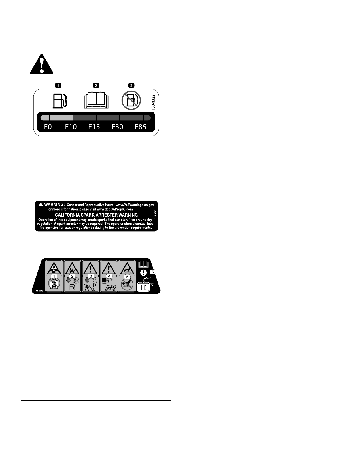
ItisaviolationofCaliforniaPublicResourceCode
Section4442or4443touseoroperatetheengineon
anyforest-covered,brush-covered,orgrass-covered
landunlesstheengineisequippedwithaspark
arrester,asdenedinSection4442,maintainedin
effectiveworkingorderortheengineisconstructed,
equipped,andmaintainedforthepreventionofre.
Ifyourequireasparkarrester,contactyourAuthorized
ServiceDealer.
Important:Theseinstallationinstructions
containengineoperationandmaintenance
informationthatsupersedestheengineoperation
andmaintenanceproceduresinyourmachine
Operator’sManual.
Beforeoperatingormaintainingthemachineor
engine,alwaysrefertotheoperatingandsafety
instructionsinyourOperator’sManual.
Savetheseinstructions.
Important:Theenginewarrantyisprovided
bytheenginemanufacturer.Pleaserefertothe
enginemanufacturer'swarrantyandemissions
systemwarrantyincludedintheliteraturepacket.
Thatwarrantyappliesonlytotheengine.Itdoes
notexpandorotherwisealteranyexpressor
impliedwarrantytermsorwarrantyperiodthat
mayapplytotheproductintowhichtheengine
isinstalled.
WARNING
CALIFORNIA
Proposition65Warning
Theengineexhaustfromthisproduct
containschemicalsknowntotheStateof
Californiatocausecancer,birthdefects,
orotherreproductiveharm.
Contents
Introduction...............................................................1
Safety.......................................................................2
SafetyandInstructionalDecals..........................2
Installation................................................................3
1PreparingtheMachine.....................................3
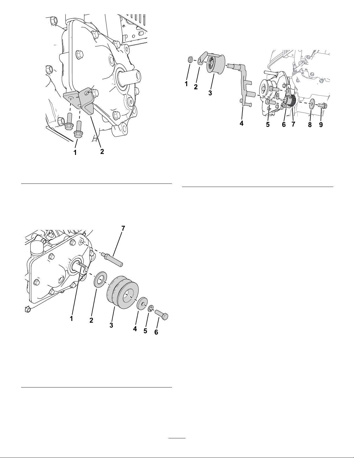
2RemovingtheExistingEngine.........................3
3InstallingtheNewEngine.................................3
4LubricatingandAdjustingtheMachine.............6
ProductOverview.....................................................7
Controls.............................................................7
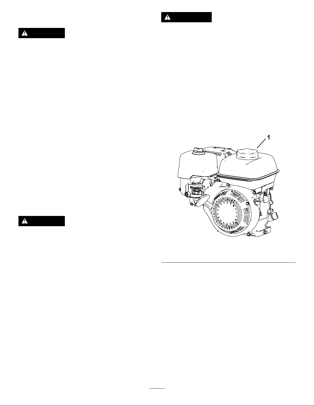
Operation..................................................................7
FuelSpecications.............................................7
UsingStabilizer/Conditioner...............................7
FillingtheFuelTank............................................8
OpeningandClosingtheFuel-Shutoff
Valve...............................................................9
Maintenance.............................................................9
RecommendedMaintenanceSchedule(s).............9
PreparingtheMachineforMaintenance............10
ServicingtheEngineOil....................................10
ServicingtheAirCleaner..................................12
ServicingtheSparkPlug...................................13
©2020—TheToro®Company
8111LyndaleAvenueSouth
Bloomington,MN55420
Registeratwww.Toro.com.OriginalInstructions(EN)
PrintedintheUSA
AllRightsReserved*3440-983*A

Safety
SafetyandInstructionalDecals
Safetydecalsandinstructionsareeasilyvisibletotheoperatorandarelocatednearanyarea
ofpotentialdanger.Replaceanydecalthatisdamagedormissing.
decal130-8322
130-8322
1.Useonlyfuelwithan
alcoholcontentbyvolume
under10%.
3.Donotusefuelwithan
alcoholcontentbyvolume
greaterthan10%.
2.ReadtheOperator's
Manualformore
informationonfuel.
decal133-8062
133-8062
decal138-2138
138-2138
1.Poisonousfumesor
toxicgases,asphyxiation
hazard—donotrunthe
engineinanenclosed
space.
4.Warning—disconnectthe
sparkplugwirebefore
performingmaintenance.
2.Explosionhazard—shut
offtheenginebefore
addingfuel;nore,open
ames,orsmokingwhen
addingfuel.
5.Hotsurfacehazard—do
nottouchthehotsurface.
3.Warning—shutoffthe
engineandclosethe
fuelshutoffvalvebefore
leavingthemachine.
6.Attention—readthe
Operator’sManualfor
informationaboutlling
thefueltank.
2

Installation
1
PreparingtheMachine
NoPartsRequired
Procedure
Preparethemachine;refertoPreparingtheMachine
forMaintenance(page10).
2
RemovingtheExisting
Engine
NoPartsRequired
Procedure
Important:Foradditionalengine-removal
instructionsandillustrations,refertothe
Greensmaster1000ServiceManual.
Important:Retainallremovedpartsforreuse
unlessotherwisenoted.
1.Removeanddiscardtheoldbellcrankcover.
2.RemoveanddiscardtheV-beltsfromthedriver
pulley.
3.Removethewireharnessfromtheengineand
thecontrol-consoleconnections.
Note:Discardthewireharness.
4.Removetheinterlockmodulefromtheengine.
5.Removethebrakeandtractionlevergrips,and
consolecover.
6.Disconnectthethrottlecablefromtheengine.
7.Disconnecttheclutchcablefromtheclutch
assemblyontheengineandtheconsole.
Note:Discardtheclutchcable.
8.Removetheoldengine.
Retaintheengine-mountingboltsandnuts.
9.Removetheengine-mountingbracketandretain
theengine-mountingbracketandbolts.
10.Cleantheframeandcheckfordamageorwear.
3
InstallingtheNewEngine
Partsneededforthisprocedure:
1Engine
1Wireharnessplate
1Wireharness
1Clutch-cablebracket
1Clutchcable
1Squarekey
1Washer(3/8x1-3/8inch)
1Bolt(3/8x3/4inch)
1Drivepulley
1Lockwasher
1Bolt(5/16x1inch)
2Bolt(7/16x1inch)
2Bolt(1/4x3/4inch)
1Bellcrankcover
1Idlerpulleyassembly
1Beltguide
1Hexnut
4Flatwasher(3/8x1-1/8inch)
1Flatwasher(5/16inch)
1Flatwasher(M20)
1Clutchlever
1Torquespring
1Clutchbracket
1Tractionpivotshaft
2V-belt
1R-clamp
1Throttlecable,158.3cm(62-3/8inches)
1Throttlecable,172.2cm(67-13/16inches)
InstallingtheEngineComponents
1.Installtheclutchplatewith2bolts(1/4x3/4
inch)asshowninFigure1.
3

g312396
Figure1
1.Clutchplate2.Bolt(1/4x3/4inch)
2.Installthesquarekeyontotheoutputshaft
(Figure2).
Note:Applyanti-seizecompoundtothekey
andoutputshaftbeforeinstalling.
g312393
Figure2
1.Squarekey5.Lockwasher
2.Washer(M20)6.Bolt(5/16x1inch)
3.Drivepulley7.Tractionpivotshaft
4.Washer(5/16inch)
3.Installthenewwasher(M20),drivepulley,
washer(5/16inch),lockwasher,andbolt(5/16
x1inch)asshowninFigure2.
4.Installthetractionpivotshafttothegearbox
(Figure2).
5.Installtheclutchbrackettothegearboxwith2
bolts(7/16x1inch)asshowninFigure3.
g312392
Figure3
1.Hexnut6.Clutchbracket
2.Beltguide7.Torquespring
3.Idlerpulleyassembly8.Washer(3/8x1-3/8inch)
4.Clutchlever9.Bolt(3/8x3/4inch)
5.Bolt(7/16x1inch)
6.Installtheclutchlevertotheclutchbracket
(Figure3).
7.Installthetorquespringtotheclutchbracket
withawasher(3/8x1-3/8inch)andabolt(3/8x
3/4inch)asshowninFigure3.
8.Installtheidlerpulleyassemblytotheclutch
leverwithabeltguideandahexnut(Figure3).
InstallingtheWireHarnessand
Cables
1.Attachthewire-harnessbrackettothefueltank
usingthe2existingangenutsthatsecurethe
tanktotheengine.
2.Installtheinterlockmoduletothewire-harness
bracketwiththewire-harnessclip.
3.Installtheengine-mountingbrackettothe
machinewiththepreviously-removedboltsand
4washers(3/8x1-1/8inch)asshowninFigure
4.
Looselyinstalltherearleftenginebolt(shownin
Figure4).
Note:Tomakeinstallingtheenginetotheframe
easier,tightentheother3bolts90%oftheway.
4

g312414
Figure4
1.Enginebolt(previously
removed)
4.Enginenut(previously
removed)
2.Engine-mounting-bracket
bolt(previouslyremoved)
5.Rearleftenginebolt
3.Washer(3/8x1-1/8inch)
4.Mounttheengineontotheengine-mounting
bracketusingthepreviously-removedboltsand
nuts(Figure4).
Note:T omakeinstallingtheenginetothe
frameeasier,tightenthebolts90%oftheway.
5.Installtheclutchcabletotheclutchplate(Figure
5).
g312403
Figure5
1.Clutchplate3.Clutch-cablespringend
2.Clutchcable4.Clutchlever
6.Installthespringendoftheclutchcabletothe
clutchlever(Figure5).
7.Installthethrottlecabletothemachine,referto
themachineServiceManual(Figure8).
•Usethethrottlecablethatis172.2cm
(67-13/16inches)longforaModel04056
tractionunit;refertoFigure6.
g327886
Figure6
1.Throttlecable2.172.2cm(67-13/16
inches)
•Usethethrottlecablethatis158.3cm
(62-3/8inches)longforallmodels,butnotfor
aModel04056tractionunit;refertoFigure7.
g327886
Figure7
1.Throttlecable2.158.3cm(62-3/8inches)
Note:Observethethrottle-cableroutingas
showninFigure8.Routethecabletotheleft
sideoftheengineandbetweentheair-cleaner
coverandfueltank.
5

g312415
Figure8
1.Clutchcable3.Wireharness
2.Throttlecable4.Interlockmodule
8.Removetherearleftboltfromtheengine
base(Figure4)andusethebolttosecurethe
R-clampandthrottlecabletotheenginebase.
9.InstallandadjusttheV-belts;refertoyour
Operator’sManual.
10.Tightenalloftheenginemountingand
engine-mountingbracketbolts(Figure4).
11.Connectthewireharnesstotheinterlock
moduleandroutetheharnessuptheleftsideof
thehandle(Figure8).
12.Plugthewireharnessintotheappropriate
consoleswitches.
Note:Connectthewireharnesstothehour
meter(ifequipped).
13.Usethewire-harnesspinstosecurethewire
harnessintoplaceundertheconsolecover.
14.Mountthegreengroundwireusingthecowling
boltunderthefueltank,andconnecttheredwire
tothesinglewireontheengine.Connectthe
remaining2harnesswires(blackandyellow)to
theenginewireharnesswith2wireconnections.
Note:Applyskin-overgreasetotheboltand
groundlugterminal.
15.Clipthewireharnesstothemountingbracket.
16.Installthenewbellcrankcoverwiththe
previously-removedhardware.
4
LubricatingandAdjusting
theMachine
NoPartsRequired
Procedure
Important:Theenginegearboxdoesnot
requiremaintenance,asitislledwitha
high-performance,long-life,syntheticsemi-uid
grease.
1.Adjusttheclutchcable;refertoyourOperator’s
Manual.
2.Adjustthethrottlecable;refertoyourOperator’s
Manual.
3.Lubricatethemachineaccordingtothe
instructionsinyourOperator’sManual.
4.Filltheenginecrankcasewithoilaccordingto
theinstructionsinyourOperator’sManual.
5.Adjusttheenginespeedtothefollowing
specications:
Highidle(noload)3450±100rpm
Lowidle(noload)1900±100rpm
6

ProductOverview
g265059
Figure9
1.Chokelever3.Recoilstarterhandle
2.Fuel-shutoffvalve
Controls
ChokeControl
Thechokecontrolislocatedonthesideoftheengine
(Figure9);youuseittohelpstartacoldengine
Note:Donotstartorrunawarmenginewiththe
chokeintheCLOSEDposition.
•Movethechokeleverallthewaytotheleft
(awayfromstarterhandle)tosetthechoketothe
CLOSEDposition.
•Movethechokeleverallthewaytotheright
(towardstarterhandle)tosetthechoketothe
OPENposition.
Fuel-ShutoffValve
Thefuel-shutoffvalveislocatedonthesideofthe
enginebelowthechokecontrol(Figure9).
Note:Closethefuel-shutoffvalvewhenthemachine
isnotusedforafewdays,duringtransporttoand
fromthejobsite,orwhenthemachineisparked
insideabuilding;refertoOpeningandClosingthe
Fuel-ShutoffValve(page9).
Operation
FuelSpecications
Fueltankcapacity:2.0L(0.59USgallons)
Recommendedfuel:Unleadedgasolinewithan
octaneratingof87orhigher((R+M)/2ratingmethod)
Ethanol:Gasolinewithupto10%ethanol(gasohol)
or15%MTBE(methyltertiarybutylether)byvolume
isacceptable.EthanolandMTBEarenotthesame.
Gasolinewith15%ethanol(E15)byvolumeisnot
approvedforuse.
•Neverusegasolinethatcontainsmorethan
10%ethanolbyvolume,suchasE15(contains
15%ethanol),E20(contains20%ethanol),orE85
(containsupto85%ethanol).
•Donotusegasolinecontainingmethanol.
•Donotstorefueleitherinthefueltankorfuel
containersoverthewinterunlessafuelstabilizer
isused.
•Donotaddoiltogasoline.
•Forbestresults,useonlyclean,fresh(lessthan
30daysold)fuel.
•Usingunapprovedgasolinemaycause
performanceproblemsand/orenginedamage,
whichmaynotbecoveredunderthewarranty
Using
Stabilizer/Conditioner
Important:Donotusefueladditivescontaining
methanolorethanol.
Addthecorrectamountoffuelstabilizer/conditioner
tothegasoline.
Note:Afuelstabilizer/conditionerismosteffective
whenmixedwithfreshgasoline.T ominimizethe
chanceofvarnishdepositsinthefuelsystem,usefuel
stabilizeratalltimes.
7

FillingtheFuelTank
DANGER
Incertainconditions,fuelisextremely
ammableandhighlyexplosive.Areor
explosionfromfuelcanburnyouandothers
andcandamageproperty.
•Fillthefueltankoutdoors,inanopenarea,
whentheengineiscold.Wipeupanyfuel
thatspills.
•Neverllthefueltankinsideanenclosed
trailer.
•Donotllthefueltankcompletelyfull.
Addfueltothefueltankuntilthelevelis6
to13mm(1/4to1/2inch)belowthebottom
ofthellerneck.Thisemptyspaceinthe
tankallowsfueltoexpand.
•Neversmokewhenhandlingfuel,andstay
awayfromanopenameorwherefuel
fumesmaybeignitedbyaspark.
•Storefuelinanapprovedcontainerand
keepitoutofthereachofchildren.Never
buymorethana30-daysupplyoffuel.
•Donotoperatewithoutentireexhaust
systeminplaceandinproperworking
condition.
DANGER
Incertainconditionsduringfueling,static
electricitycanbereleased,causingaspark
whichcanignitethefuelvapors.Areor
explosionfromfuelcanburnyouandothers
andcandamageproperty.
•Alwaysplacefuelcontainersontheground
awayfromyourvehiclebeforelling.
•Donotllfuelcontainersinsideavehicle
oronatruckortrailerbedbecauseinterior
carpetsorplastictruck-bedlinersmay
insulatethecontainerandslowthelossof
anystaticcharge.
•Whenpractical,removeequipmentfrom
thetruckortrailerandfuelitonthe
ground.Ifthisisnotpossible,thenfuel
suchequipmentwithaportablecontainer
ratherthanfromafuel-dispensernozzle.
•Ifyoumustuseafuel-dispensernozzle,
keepthenozzleincontactwiththerimof
thefueltankorcontaineropeningatall
timesuntilfuelingiscomplete.
WARNING
Fuelisharmfulorfatalifswallowed.
Long-termexposuretovaporscancause
seriousinjuryandillness.
•Avoidprolongedbreathingofvapors.
•Keepyourfaceawayfromthenozzleand
fueltankorconditionerbottleopening.
•Avoidcontactwithskin;washoffspills
withsoapandwater.
1.Parkthemachineonalevelsurfaceandshut
offtheengine.
2.Allowtheenginetocool.
3.Cleanaroundthefuel-tankcapandremoveit
(Figure10).
g265976
Figure10
1.Fuel-tankcap
4.Fillthetankwithfueluntilthelevelisjustinside
themeshlterbasket.
Donotllintothellerneckofthetank.
Important:Donotllthetankmoreabove
thellermeshbecausethefuelneedsroom
toexpand.
5.Installthefuel-tankcapsecurely.
6.Wipeupanyspilledfuel.
8

OpeningandClosingthe
Fuel-ShutoffValve
Controlfuelowtotheenginewiththefuel-shutoff
valveasfollows:
•T oopenthefuelvalve,turnthefuel-shutoffvalve
handletowardtherecoilstarterhandle(Figure11).
•T oshutthefuelvalve,turnthefuel-shutoffvalve
handleawayfromtherecoilstarterhandle(Figure
11).
g265993
Figure11
1.Turnthefuelvalveleverto
theONposition
2.FuelvalveleverintheOFF
position
Maintenance
Important:Refertoyourengineowner’smanual
foradditionalmaintenanceprocedures.
Important:Theenginegearbox(Figure12)does
notrequiremaintenance,asitislledwitha
high-performance,long-lifesyntheticsemi-uid
grease.
g312416
Figure12
1.Gearbox
RecommendedMaintenanceSchedule(s)
MaintenanceService
IntervalMaintenanceProcedure
Aftertherst20hours•Changetheengineoil.
Beforeeachuseordaily•Checktheengine-oillevel.
•Inspecttheair-lterelements.
Every50hours•Cleantheair-lterelements.
Every100hours•Changetheengineoil.
•Inspectandadjustthesparkplug;replaceitifnecessary.
Every300hours•Replacethepaperlterelement(Morefrequentlyindustyoperatingconditions).
•Replacethesparkplug.
9

PreparingtheMachinefor
Maintenance
WARNING
Whileyouaremaintainingoradjustingthe
machine,someonecouldstarttheengine.
Accidentallystartingtheenginecould
seriouslyinjureyouorotherbystanders.
Removethekeyfromtheignition,engage
parkingbrake,andpullthewire(s)offthe
sparkplug(s)beforeyoudoanymaintenance.
Alsopushthewire(s)asidesoitdoesnot
accidentallycontactthesparkplug(s).
Performthefollowingbeforeservicing,cleaning,or
makinganyadjustmentstothemachine.
1.Parkthemachineonalevelsurface.
2.Shutofftheengineandremovethekeyfromthe
machine(ifequipped).
3.Engagetheparkingbrake.
4.Waitforallmovingpartstostopandallowthe
enginetocoolbeforeservicingorstoring.
5.Disconnectthespark-plugwire(Figure13).
g265998
Figure13
1.Spark-plugwire
ServicingtheEngineOil
Fillthecrankcasewithapproximately0.56L(19
oz)oftheproperviscosityoilbeforestarting.The
engineusesahigh-qualityoilthathastheAmerican
PetroleumInstitute(API)serviceclassicationofSJor
higher.Selecttheproperoilviscosity(weight)based
ontheambienttemperature.Figure14illustratesthe
temperature/viscosityrecommendations.
g013375
Figure14
Note:Multi-gradeoils(5W-20,10W-30and10W-40)
increaseoilconsumption.Checktheengine-oillevel
morefrequentlywhenyouusetheseoils.
CheckingtheEngine-OilLevel
ServiceInterval:Beforeeachuseordaily
Theidealtimetochecktheengine-oilleveliswhenthe
engineiscoolorbeforeyouhavestartedtheengine
fortheday.Ifyouhavealreadyrantheengine,allow
theoiltodrainbackdowntothesumpforatleast10
minutesbeforeyouchecktheengine-oillevel.
1.Shutofftheengineandwaitforallmoving
partstostop;refertoPreparingtheMachinefor
Maintenance(page10).
2.Positionthemachinesothattheengineislevel,
andcleantheareaaroundtheoil-lltube(Figure
15).
10

g266053
Figure15
1.Dipstick2.Drainplugandwasher
3.Removethedipstickbyrotatingit
counterclockwise.
4.Removethedipstickandwipetheendclean.
5.Insertthedipstickfullyintotheoil-lltube,but
donotthreaditin.
6.Removethedipstickandchecktheengine-oil
level(Figure16).
g019686
Figure16
1.Fillertube4.Lowerlimit
2.Dipstick5.Drainplug
3.Upperlimit
7.Iftheengine-oillevelisincorrect,addordrainoil
tocorrectthelevel;refertoChangingtheEngine
Oil(page11).
ChangingtheEngineOil
ServiceInterval:Aftertherst20hours
Every100hours
WARNING
Oilmaybehotaftertheenginehasbeenrun,
andcontactwithhotoilcancausesevere
personalinjury.
Avoidcontactingthehotengineoilwhenyou
drainit.
1.Shutofftheengineandwaitforallmoving
partstostop;refertoPreparingtheMachinefor
Maintenance(page10).
2.Raisetheengineoffthegroundandplaceapan
underthedrainplugtocatchtheoil.
3.Removethedrainplug(Figure15).
4.Whentheoilhasdrainedcompletely,lowerthe
enginetotheground,replacethedrainplugand
washer,andtorquetheplugto18N⋅m(13ft-lb).
Note:Disposeoftheusedoilatacertied
recyclingcenter.
5.Removethedipstick,andslowlypouroilintothe
oil-llholeuntiltheoilisatthecorrectlevel.
6.Ensurethattheoilisatthecorrectlevelonthe
dipstick;refertoCheckingtheEngine-OilLevel
(page10).
7.Replaceandsecurethedipstick.
8.Wipeupanyspilledoil.
9.Connectthewiretothesparkplug.
11

ServicingtheAirCleaner
ServiceInterval:Beforeeachuseordaily
Every50hours
Every300hours/Yearly(whichevercomesrst)
Important:Donotoperatetheenginewithout
theairlterassembly;extremeenginedamage
willoccur.
1.Shutofftheengineandwaitforallmoving
partstostop;refertoPreparingtheMachinefor
Maintenance(page10).
2.Removethewingnutsecuringtheair-cleaner
cover(Figure17).
3.Removetheair-cleanercover.
Note:Ensurethatnodirtordebrisfromthe
air-cleanercoverfallintothebase.
4.Removethefoamandpaperelementsfromthe
base.
5.Removethefoamelementfromthepaper
element.
6.Inspectthefoamandpaperelements;replace
themiftheyaredamagedorexcessivelydirty.
g265999
Figure17
1.Wingnut4.Paperlterelement
2.Air-cleanercover5.Gasketandairduct
3.Foamelement
7.Cleanthepaperelementbytappingitgentlyto
removethedirt.
Note:Donottrytobrushdirtoffthepaper
element;brushingforcesthedirtintothebers.
Replacetheelementiftappingitfailstoremove
thedirt.
8.Cleanthefoamelementinwarm,soapywater
orinanonammablesolvent.
Note:Donotusegasolinetocleanthefoam
elementbecauseitcouldcreateariskofreor
explosion.
9.Rinseanddrythefoamelementthoroughly.
10.Wipedirtfromthebaseandthecoverwitha
moistrag.
Note:Ensurethatdirtanddebrisdonotenter
theairductleadingtothecarburetor.
11.Installtheair-cleanerelementsandensurethat
theyareproperlypositioned.Installthelower
wingnut.
12.Installthecoverandinstalltheupperwingnut
tosecureit.
12

ServicingtheSparkPlug
ServiceInterval:Every100hours
Every300hours
UseanNGKBPR6ESsparkplugorequivalent.
1.Shutofftheengineandwaitforallmoving
partstostop;refertoPreparingtheMachinefor
Maintenance(page10).
2.Cleanaroundthesparkplug.
3.Removethesparkplugfromthecylinderhead.
Important:Replaceacracked,fouled,or
dirtysparkplug.Donotsandblast,scrape,
orcleantheelectrodesbecauseengine
damagecouldresultfromgritenteringthe
cylinder.
4.Setthegapontheplugto0.7to0.8mm(0.028
to0.031inch)
g000533
Figure18
1.Center-electrodeinsulator3.Airgap
2.Sideelectrode
5.Carefullyinstallthesparkplugbyhand(toavoid
crossthreading)untilitishandtight.
6.Tightenthesparkpluganadditional1/2turnif
itisnew;otherwise,tightenitanadditional1/8
to1/4turn.
Important:Aloosesparkplugcanbecome
veryhotandcandamagetheengine;
overtighteningasparkplugmaydamagethe
threadsinthecylinderhead.
7.Connectthewiretothesparkplug.
13

Notes:

Notes:

CaliforniaProposition65WarningInformation
Whatisthiswarning?
Youmayseeaproductforsalethathasawarninglabellikethefollowing:
WARNING:CancerandReproductiveHarm—www.p65Warnings.ca.gov.
WhatisProp65?
Prop65appliestoanycompanyoperatinginCalifornia,sellingproductsinCalifornia,ormanufacturingproductsthatmaybesoldinorbroughtinto
California.ItmandatesthattheGovernorofCaliforniamaintainandpublishalistofchemicalsknowntocausecancer,birthdefects,and/orother
reproductiveharm.Thelist,whichisupdatedannually,includeshundredsofchemicalsfoundinmanyeverydayitems.ThepurposeofProp65isto
informthepublicaboutexposuretothesechemicals.
Prop65doesnotbanthesaleofproductscontainingthesechemicalsbutinsteadrequireswarningsonanyproduct,productpackaging,orliteraturewith
theproduct.Moreover,aProp65warningdoesnotmeanthataproductisinviolationofanyproductsafetystandardsorrequirements.Infact,the
CaliforniagovernmenthasclariedthataProp65warning“isnotthesameasaregulatorydecisionthataproductis‘safe’or‘unsafe.’”Manyofthese
chemicalshavebeenusedineverydayproductsforyearswithoutdocumentedharm.Formoreinformation,gotohttps://oag.ca.gov/prop65/faqs-view-all.
AProp65warningmeansthatacompanyhaseither(1)evaluatedtheexposureandhasconcludedthatitexceedsthe“nosignicantrisklevel”;or(2)
haschosentoprovideawarningbasedonitsunderstandingaboutthepresenceofalistedchemicalwithoutattemptingtoevaluatetheexposure.
Doesthislawapplyeverywhere?
Prop65warningsarerequiredunderCalifornialawonly.ThesewarningsareseenthroughoutCaliforniainawiderangeofsettings,includingbutnot
limitedtorestaurants,grocerystores,hotels,schools,andhospitals,andonawidevarietyofproducts.Additionally,someonlineandmailorder
retailersprovideProp65warningsontheirwebsitesorincatalogs.
HowdotheCaliforniawarningscomparetofederallimits?
Prop65standardsareoftenmorestringentthanfederalandinternationalstandards.TherearevarioussubstancesthatrequireaProp65warning
atlevelsthatarefarlowerthanfederalactionlimits.Forexample,theProp65standardforwarningsforleadis0.5μg/day,whichiswellbelow
thefederalandinternationalstandards.
Whydon’tallsimilarproductscarrythewarning?
•ProductssoldinCaliforniarequireProp65labellingwhilesimilarproductssoldelsewheredonot.
•AcompanyinvolvedinaProp65lawsuitreachingasettlementmayberequiredtouseProp65warningsforitsproducts,butothercompanies
makingsimilarproductsmayhavenosuchrequirement.
•TheenforcementofProp65isinconsistent.
•CompaniesmayelectnottoprovidewarningsbecausetheyconcludethattheyarenotrequiredtodosounderProp65;alackofwarningsfora
productdoesnotmeanthattheproductisfreeoflistedchemicalsatsimilarlevels.
WhydoesToroincludethiswarning?
Torohaschosentoprovideconsumerswithasmuchinformationaspossiblesothattheycanmakeinformeddecisionsabouttheproductstheybuyand
use.T oroprovideswarningsincertaincasesbasedonitsknowledgeofthepresenceofoneormorelistedchemicalswithoutevaluatingthelevelof
exposure,asnotallthelistedchemicalsprovideexposurelimitrequirements.WhiletheexposurefromT oroproductsmaybenegligibleorwellwithinthe
“nosignicantrisk”range,outofanabundanceofcaution,T orohaselectedtoprovidetheProp65warnings.Moreover,ifTorodoesnotprovidethese
warnings,itcouldbesuedbytheStateofCaliforniaorbyprivatepartiesseekingtoenforceProp65andsubjecttosubstantialpenalties.
RevA
Table of contents
Other Toro Engine manuals

Toro
Toro LC175FDS User manual

Toro
Toro 138-2139 User manual

Toro
Toro LC1P92F User manual

Toro
Toro GTS 200 User manual

Toro
Toro GREENSMASTER 3100 User manual

Toro
Toro 139-5637 User manual

Toro
Toro Prior LC1P65FA User manual

Toro
Toro Z Master 500 Series User manual

Toro
Toro LC1P65FC User manual

Toro
Toro GTS 150 User manual