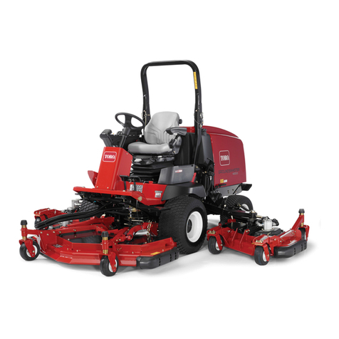
Toro 4530 User manual

FormNo.3385-965RevA
Greensmaster®3320TriFlex™
TractionUnit
ModelNo.04530—SerialNo.314004001andUp
g014597
Registeratwww.Toro.com.
OriginalInstructions(EN)*3385-965*A

ThisproductcomplieswithallrelevantEuropeandirectives;
fordetails,pleaseseetheseparateproductspecicDeclaration
ofConformity(DOC)sheet.
WARNING
CALIFORNIA
Proposition65Warning
Thisproductcontainsachemicalorchemicals
knowntotheStateofCaliforniatocausecancer,
birthdefects,orreproductiveharm.
Theengineexhaustfromthisproduct
containschemicalsknowntotheStateof
Californiatocausecancer,birthdefects,
orotherreproductiveharm.
Important:Thisengineisnotequippedwithaspark
arrestermufer.ItisaviolationofCaliforniaPublic
ResourceCodeSection4442touseoroperatetheengine
onanyforest-covered,brush-covered,orgrass-covered
land.Otherstatesorfederalareasmayhavesimilarlaws.
Introduction
Thismachineisaride-on,reel-bladelawnmowerintended
tobeusedbyprofessional,hiredoperatorsincommercial
applications.Itisprimarilydesignedforcuttinggrasson
well-maintainedlawnsinparks,golfcourses,sportselds,
andoncommercialgrounds.Itisnotdesignedforcutting
brush,mowinggrassandothergrowthalongsidehighways,
orforagriculturaluses.
Readthisinformationcarefullytolearnhowtooperateand
maintainyourproductproperlyandtoavoidinjuryand
productdamage.Youareresponsibleforoperatingthe
productproperlyandsafely.
YoumaycontactTorodirectlyatwww.Toro.comforproduct
andaccessoryinformation,helpndingadealer,ortoregister
yourproduct.
Wheneveryouneedservice,genuineToroparts,oradditional
information,contactanAuthorizedServiceDealerorToro
CustomerServiceandhavethemodelandserialnumbersof
yourproductready.Figure1identiesthelocationofthe
modelandserialnumbersontheproduct.Writethenumbers
inthespaceprovided.
g014685
1
Figure1
1.Modelandserialnumberlocation
ModelNo.
SerialNo.
Thismanualidentiespotentialhazardsandhassafety
messagesidentiedbythesafetyalertsymbol(Figure2),
whichsignalsahazardthatmaycauseseriousinjuryordeath
ifyoudonotfollowtherecommendedprecautions.
Figure2
1.Safetyalertsymbol
Thismanualuses2wordstohighlightinformation.
Importantcallsattentiontospecialmechanicalinformation
andNoteemphasizesgeneralinformationworthyofspecial
attention.
©2014—TheToro®Company
8111LyndaleAvenueSouth
Bloomington,MN554202
Contactusatwww.Toro.com.
PrintedintheUSA
AllRightsReserved

Contents
Introduction..................................................................2
Safety...........................................................................4
SafeOperatingPractices...........................................4
ToroMowerSafety..................................................6
SoundPowerLevel..................................................7
SoundPressureLevel...............................................7
VibrationLevel......................................................7
SafetyandInstructionalDecals.................................8
Setup...........................................................................11
1InstallingtheRollBar...........................................12
2InstallingtheSeat.................................................12
3InstallingtheSteeringWheel..................................13
4ActivatingandChargingtheBattery........................13
5InstallingtheOptionalOilCooler...........................14
6InstallingtheGrassBasketHooks..........................15
7InstallingtheCuttingUnits...................................15
8AddingRearWeight.............................................17
9InstallingEUDecals.............................................17
ProductOverview.........................................................18
Controls...............................................................18
Specications........................................................25
Attachments/Accessories........................................25
Operation....................................................................26
ThinkSafetyFirst...................................................26
CheckingtheEngineOil..........................................26
FillingtheFuelTank...............................................26
CheckingtheHydraulicFluidLevel...........................27
CheckingtheReel-to-BedknifeContact.....................28
CheckingtheTirePressure......................................28
CheckingtheTorqueoftheWheelNuts.....................28
Breaking-intheMachine..........................................28
StartingtheEngine.................................................29
CheckingtheSafetyInterlockSystem........................29
InstallingandRemovingtheCuttingUnits.................30
TrainingPeriod......................................................32
Mowing................................................................32
TransportingtheMachine........................................33
InspectingandCleaningAfterMowing......................33
TowingtheMachine...............................................33
Maintenance.................................................................34
RecommendedMaintenanceSchedule(s)......................34
DailyMaintenanceChecklist....................................35
Lubrication...............................................................36
GreasingtheMachine.............................................36
EngineMaintenance..................................................36
ServicingtheAirCleaner.........................................36
ChangingtheEngineOilandFilter...........................37
ReplacingtheSparkPlugs........................................37
FuelSystemMaintenance...........................................38
ReplacingtheFuelFilter..........................................38
InspectingtheFuelLinesandConnections.................38
ElectricalSystemMaintenance....................................38
ServicingtheBattery...............................................38
ServicingtheFuses.................................................39
DriveSystemMaintenance.........................................39
AdjustingtheTransmissionforNeutral.....................39
AdjustingtheTransportSpeed.................................40
AdjustingtheMowingSpeed....................................40
BrakeMaintenance....................................................41
AdjustingtheBrakes...............................................41
HydraulicSystemMaintenance....................................41
ChangingtheHydraulicOilandFilter........................41
CheckingtheHydraulicLinesandHoses....................42
CuttingUnitMaintenance...........................................42
BacklappingtheReels.............................................42
Storage........................................................................43
3

Safety
ThismachinemeetsorexceedsCENstandardEN
836:1997,ISOstandard5395:1990,andANSIB71.4-2012
specicationsineffectatthetimeofproductionwhen54
kg(119lb)ofweightisaddedtotherearwheel.
Note:Theadditionofattachmentsmadebyother
manufacturersthatdonotmeetAmericanNationalStandards
Institutecerticationwillcausenoncomplianceofthis
machine.
Improperuseormaintenancebytheoperatororowner
canresultininjury.Toreducethepotentialforinjury,
complywiththesesafetyinstructionsandalwayspay
attentiontothesafetyalertsymbol(Figure2),which
meansCaution,Warning,orDanger—personalsafety
instruction.Failuretocomplywiththeinstructionmay
resultinpersonalinjuryordeath.
SafeOperatingPractices
ThefollowinginstructionsareadaptedfromCENstandard
EN836:1997,ISOstandard5395:1990,andANSI
B71.4-2012.
Training
•ReadtheOperator’sManualandothertrainingmaterial
carefully.Befamiliarwiththecontrols,safetysigns,and
theproperuseoftheequipment.
•Iftheoperatorormechaniccannotreadthelanguage
ofthismanual,itistheowner’sresponsibilitytoexplain
thismaterialtothem.
•Neverallowchildrenorpeopleunfamiliarwiththese
instructionstouseorservicethemower.Local
regulationsmayrestricttheageoftheoperator.
•Nevermowwhilepeople,especiallychildren,orpetsare
nearby.
•Keepinmindthattheoperatororuserisresponsiblefor
accidentsorhazardsoccurringtootherpeopleortheir
property.
•Donotcarrypassengers.
•Alldriversandmechanicsshouldseekandobtain
professionalandpracticalinstruction.Theowneris
responsiblefortrainingtheusers.Suchinstructionshould
emphasize:
–theneedforcareandconcentrationwhenworking
withride-onmachines;
–controlofaride-onmachineslidingonaslopewill
notberegainedbytheapplicationofthebrake.The
mainreasonsforlossofcontrolare:
◊insufcientwheelgrip;
◊beingdriventoofast;
◊inadequatebraking;
◊thetypeofmachineisunsuitableforthetask;
◊lackofawarenessoftheeffectofground
conditions,especiallyslopes.
◊Theowner/usercanpreventandisresponsible
foraccidentsorinjuriesoccurringtopeople,or
damagetoproperty.
Preparation
•Whilemowing,alwayswearsubstantialfootwear,long
trousers,hardhat,safetyglasses,andhearingprotection.
Longhair,looseclothing,orjewelrymaygettangled
inmovingparts.Donotoperatetheequipmentwhen
barefootorwearingopensandals.
•Thoroughlyinspecttheareawheretheequipmentisto
beusedandremoveallobjectswhichmaybethrownby
themachine.
•Replacefaultysilencers/mufers.
•Evaluatetheterraintodeterminewhataccessoriesand
attachmentsareneededtoproperlyandsafelyperform
thejob.Onlyuseaccessoriesandattachmentsapproved
bythemanufacturer.
•Checkthatoperator’spresencecontrols,safetyswitches
andshieldsareattachedandfunctioningproperly.Donot
operateunlesstheyarefunctioningproperly.
Operation
•Donotoperatetheengineinaconnedspacewhere
dangerouscarbonmonoxidefumescancollect.
•Mowonlyindaylightoringoodarticiallight.
•Beforeattemptingtostarttheengine,disengageallblade
attachmentclutches,shiftintoneutral,andengagethe
parkingbrake.
•Rememberthereisnosuchthingasasafeslope.Travel
ongrassslopesrequiresparticularcare.Toguardagainst
overturning:
–donotstoporstartsuddenlywhengoingupor
downhill;
–machinespeedsshouldbekeptlowonslopesand
duringtightturns;
–stayalertforhumpsandhollowsandotherhidden
hazards;
–nevermowacrossthefaceoftheslope,unlessthe
mowerisdesignedforthispurpose.
•Stayalertforholesintheterrainandotherhiddenhazards.
•Watchoutfortrafcwhencrossingornearroadways.
•Stopthebladesfromrotatingbeforecrossingsurfaces
otherthangrass.
•Whenusinganyattachments,neverdirectdischargeof
materialtowardbystandersnorallowanyonenearthe
machinewhileinoperation.
•Neveroperatethemachinewithdamagedguards,shields,
orwithoutsafetyprotectivedevicesinplace.Besureall
4

interlocksareattached,adjustedproperly,andfunctioning
properly.
•Donotchangetheenginegovernorsettingsoroverspeed
theengine.Operatingtheengineatexcessivespeedmay
increasethehazardofpersonalinjury.
•Beforeleavingtheoperator’sposition:
–stoponlevelground;
–disengagethepowertake-offandlowerthe
attachments;
–changeintoneutralandsettheparkingbrake;
–stoptheengineandremovethekey.
•Disengagedrivetoattachmentswhentransportingornot
inuse.
•Stoptheengineanddisengagedrivetoattachment:
–beforerefuelling;
–beforeremovingthegrasscatcher/catchers;
–beforemakingheightadjustmentunlessadjustment
canbemadefromtheoperator’sposition.
–beforeclearingblockages;
–beforechecking,cleaningorworkingonthemower;
–afterstrikingaforeignobjectorifanabnormal
vibrationoccurs.Inspectthemowerfordamage
andmakerepairsbeforerestartingandoperatingthe
equipment.
•Reducethethrottlesettingbeforestoppingtheengine
and,iftheengineisprovidedwithafuelshut-offvalve,
turnthefueloffattheconclusionofmowing.
•Keephandsandfeetawayfromthecuttingunits.
•Lookbehindanddownbeforebackinguptobesureof
aclearpath.
•Slowdownandusecautionwhenmakingturnsand
crossingroadsandsidewalks.Stopthereelswhennot
mowing.
•Donotoperatethemowerundertheinuenceofalcohol
ordrugs.
•Lightningcancausesevereinjuryordeath.Iflightning
isseenorthunderisheardinthearea,donotoperate
themachine;seekshelter.
•Usecarewhenloadingorunloadingthemachineintoa
trailerortruck.
•Usecarewhenapproachingblindcorners,shrubs,trees,
orotherobjectsthatmayobscurevision.
RolloverProtectionSystem(ROPS)-
UseandMaintenance
•TheROPSisanintegralandeffectivesafetydevice.Keep
afoldingROPSintheraisedandlockedpositionanduse
theseatbeltwhenoperatingthemachine.
•LowerafoldingROPStemporarilyonlywhenabsolutely
necessary.Donotweartheseatbeltwhenfoldeddown.
•Beawarethereisnorolloverprotectionwhenafolded
ROPSisinthedownposition.
•Becertainthattheseatbeltcanbereleasedquicklyin
theeventofanemergency.
•Checktheareatobemowedandneverfolddowna
foldingROPSinareaswherethereareslopes,dropoffs
orwater.
•Checkcarefullyforoverheadclearances(i.e.branches,
doorways,electricalwires)beforedrivingunderany
objectsanddonotcontactthem.
•KeeptheROPSinsafeoperatingconditionby
periodicallythoroughlyinspectingfordamageand
keepingallmountingfastenerstight.
•ReplaceadamagedROPS.Donotrepairorrevise.
•DonotremovetheROPS.
•AnyalterationstoaROPSmustbeapprovedbythe
manufacturer.
SafeHandlingofFuels
•Toavoidpersonalinjuryorpropertydamage,use
extremecareinhandlinggasoline.Gasolineisextremely
ammableandthevaporsareexplosive.
•Extinguishallcigarettes,cigars,pipes,andothersources
ofignition.
•Useonlyanapprovedfuelcontainer.
•Neverremovefuelcaporaddfuelwiththeengine
running.
•Allowenginetocoolbeforerefueling.
•Neverrefuelthemachineindoors.
•Neverstorethemachineorfuelcontainerwherethereis
anopename,spark,orpilotlightsuchasonawater
heateroronotherappliances.
•Neverllcontainersinsideavehicleoronatruckor
trailerbedwithaplasticliner.Alwaysplacecontainerson
thegroundawayfromyourvehiclebeforelling.
•Removeequipmentfromthetruckortrailerandrefuelit
ontheground.Ifthisisnotpossible,thenrefuelsuch
equipmentwithaportablecontainer,ratherthanfroma
fueldispensernozzle.
•Keepthenozzleincontactwiththerimofthefueltank
orcontaineropeningatalltimesuntilfuelingiscomplete.
•Donotuseanozzlelockopendevice.
•Iffuelisspilledonclothing,changeclothingimmediately.
•Neveroverllfueltank.Replacefuelcapandtighten
securely.
MaintenanceandStorage
•Keepallnuts,boltsandscrewstighttobesurethe
equipmentisinsafeworkingcondition.
•Neverstoretheequipmentwithfuelinthetankinsidea
buildingwherefumesmayreachanopenameorspark.
5

•Allowtheenginetocoolbeforestoringinanyenclosure.
•Toreducetheriskofrehazard,keeptheengine,
silencer/mufer,batterycompartment,andfuelstorage
areafreeofgrass,leaves,orexcessivegrease.
•Replacewornordamagedpartsforsafety.
•Checkthegrasscatcherfrequentlyforwearor
deterioration.
•Keepallpartsingoodworkingconditionandallhardware
andhydraulicttingstightened.Replaceallwornor
damagedpartsanddecals.
•Ifthefueltankhastobedrained,dothisoutdoors.
•Becarefulduringadjustmentofthemachinetoprevent
entrapmentofthengersbetweenmovingbladesand
xedpartsofthemachine.
•Onmulti-reelmachines,takecareasrotatingonereelcan
causeotherreelstorotate.
•Disengagedrives,lowerthecuttingunits,setparking
brake,stopengineandremovekey.Waitforallmovement
tostopbeforeadjusting,cleaningorrepairing.
•Cleangrassanddebrisfromcuttingunits,drives,mufers,
andenginetohelppreventres.Cleanupoilorfuel
spillage.
•Usejackstandstosupportcomponentswhenrequired.
•Carefullyreleasepressurefromcomponentswithstored
energy.
•Disconnectbatterybeforemakinganyrepairs.Disconnect
thenegativeterminalrstandthepositivelast.Reconnect
positiverstandnegativelast.
•Usecarewhencheckingthereels.Wrapthereelsorwear
gloves,andusecautionwhenservicingthem.
•Keephandsandfeetawayfrommovingparts.Ifpossible,
donotmakeadjustmentswiththeenginerunning.
•Chargebatteriesinanopenwellventilatedarea,away
fromsparkandames.Unplugchargerbeforeconnecting
ordisconnectingfrombattery.Wearprotectiveclothing
anduseinsulatedtools.
•Neverstorethemachineorfuelcontainerwherethereis
anopename,spark,orpilotlightsuchasonawater
heateroronotherappliances.
ToroMowerSafety
ThefollowinglistcontainssafetyinformationspecictoToro
productsorothersafetyinformationthatyoumustknowthat
isnotincludedintheANSIstandards.
Thisproductiscapableofamputatinghandsandfeetand
throwingobjects.Alwaysfollowallsafetyinstructionsto
avoidseriousinjuryordeath.
Useofthisproductforpurposesotherthanitsintendeduse
couldprovedangeroustouserandbystanders.
Operation
•Knowhowtostoptheenginequickly.
•Alwayswearsubstantialshoes.Donotoperatethe
machinewhilewearingsandals,tennisshoes,orsneakers.
Wearingsafetyshoesandlongpantsisadvisableand
requiredbysomelocalordinancesandinsurance
regulations.
•Handlefuelcarefully.Wipeupanyspills.
•Checkthesafetyinterlockswitchesdailyforproper
operation.Ifaswitchhasfailed,replacetheswitchbefore
operatingthemachine.
•Beforeattemptingtostarttheengine,sitontheseat,pull
ontheraise/lowermowcontroltoensurethatthecutting
unitsaredisengaged,ensurethatthetractionpedalisin
neutral,andengagetheparkingbrake.
•Usingthemachinedemandsattention.Topreventloss
ofcontrol:
–Donotdriveclosetosandtraps,ditches,creeks,or
otherhazards.
–Reducespeedwhenmakingsharpturns.Avoid
suddenstopsandstarts.
–Thismachineisnotdesignedorequippedforon-road
useandisa“slow-movingvehicle.”Ifyoumustcross
ortravelonapublicroad,youshouldbeawareofand
complywithlocalregulations,suchasrequiredlights,
slowmovingvehiclesigns,andreectors.
–Watchoutfortrafcwhennearorcrossingroads.
Alwaysyieldtheright-of-way.
–Applytheservicebrakeswhengoingdownhillto
keepforwardspeedslowandtomaintaincontrolof
themachine.
•Shuttheengineoffbeforeemptyingthebaskets.
•Raisethecuttingunitswhendrivingfromoneworkarea
toanother.
•Donottouchtheengine,mufer,orexhaustpipewhile
theengineisrunningorsoonafterithasstoppedbecause
theseareascouldbehotenoughtocauseburns.
•Stayclearoftherotatingscreenatthesideoftheengine
topreventdirectcontactwithyourbodyorclothing.
•Ifacuttingunitstrikesasolidobjectorvibrates
abnormally,stopimmediately,turntheengineoff,waitfor
allmotiontostop,andinspectthemachinefordamage.
Adamagedreelorbedknifemustberepairedorreplaced
beforeoperationiscontinued.
•Beforegettingoffoftheseat,movethefunctionalcontrol
levertoneutral(N),raisethecuttingunitsandwaitfor
thereelstostopspinning.Settheparkingbrake.Stopthe
engineandremovethekeyfromtheignitionswitch.
•Traverseslopescarefully.Donotstartorstopsuddenly
whentravelinguphillordownhill.
•Theoperatormustbeskilledandtrainedinhowtodrive
onhillsides.Failuretousecautiononslopesorhillsmay
causelossofcontrolandcausethemachinetotiporroll,
possiblyresultinginpersonalinjuryordeath.
6
•Iftheenginestallsorlosesheadwayandcannotmakeit
tothetopofaslope,donotturnthemachinearound.
Alwaysbackslowly,straightdowntheslope.
•Whenapersonorpetappearsunexpectedlyinornear
themowingarea,stopmowing.Carelessoperation,
combinedwithterrainangles,ricochets,orimproperly
positionedguardscanleadtothrownobjectinjuries.Do
notresumemowinguntiltheareaiscleared.
•Wheneverthemachineisleftunattended,makesurethe
cuttingunitsarefullyraised,thereelsarenotspinning,
thekeyisremovedfromtheignitionswitch,andthe
parkingbrakeisset.
•AlwaysusetheseatbeltwiththeROPSwhenoperating
themachine.
•Donotoperatethismachineonslopesexceeding15
degrees.
MaintenanceandStorage
•Makesureallhydrauliclineconnectorsaretightandall
hydraulichosesandlinesareingoodconditionbefore
applyingpressuretothesystem.
•Keepyourbodyandhandsawayfrompinholeleaksor
nozzlesthatejecthydraulicuidunderhighpressure.
Usepaperorcardboard,notyourhands,tosearchfor
leaks.Hydraulicuidescapingunderpressurecanhave
sufcientforcetopenetratetheskinandcauseserious
injury.
•Beforedisconnectingorperforminganyworkonthe
hydraulicsystem,allpressureinthesystemmustbe
relievedbystoppingtheengineandloweringthecutting
unitsandattachmentstotheground.
•Checkallfuellinesfortightnessandwearonaregular
basis.Tightenorrepairthemasneeded.
•Iftheenginemustberunningtoperformamaintenance
adjustment,keephands,feet,clothing,andanypartsof
thebodyawayfromthecuttingunits,attachments,and
anymovingparts,especiallythescreenatthesideofthe
engine.Keepeveryoneaway.
•Donotoverspeedtheenginebychanginggovernor
settings.Toensuresafetyandaccuracy,havean
AuthorizedToroDistributorcheckthemaximumengine
speedwithatachometer..
•Theenginemustbeshutoffbeforecheckingtheoilor
addingoiltothecrankcase.
•Ifmajorrepairsareeverneededorifassistanceisdesired,
contactanAuthorizedToroDistributor.
•Toassureoptimumperformanceandcontinuedsafety
certicationofthemachine,useonlygenuineToro
replacementpartsandaccessories.Replacementparts
andaccessoriesmadebyothermanufacturerscouldbe
dangerous,andsuchusecouldvoidtheproductwarranty.
•Disconnectthecuttingunitsfromthepowersupply,
usingthecuttingunitpowerdisconnectcouplers,before
performinganyworkonthecuttingunits.
SoundPowerLevel
Thisunithasaguaranteedsoundpowerlevelof97dBA,
whichincludesanUncertaintyValue(K)of1dBA.
Soundpowerlevelwasdeterminedaccordingtothe
proceduresoutlinedinISO11094.
SoundPressureLevel
Thisunithasasoundpressurelevelattheoperator’searof81
dBA,whichincludesanUncertaintyValue(K)of1dBA.
Soundpressurelevelwasdeterminedaccordingtothe
proceduresoutlinedinEN836.
VibrationLevel
Hand-Arm
Measuredvibrationlevelforrighthand=0.20m/s2
Measuredvibrationlevelforlefthand=0.31m/s2
UncertaintyValue(K)=0.15m/s2
Measuredvaluesweredeterminedaccordingtotheprocedures
outlinedinEN836.
WholeBody
Measuredvibrationlevel=0.14m/s2
UncertaintyValue(K)=0.07m/s2
Measuredvaluesweredeterminedaccordingtotheprocedures
outlinedinEN836.
7

SafetyandInstructionalDecals
Safetydecalsandinstructionsareeasilyvisibletotheoperatorandarelocatednearanyareaofpotential
danger.Replaceanydecalthatisdamagedorlost.
119-9345
115-8156
1.Reelheight3.8Bladecuttingunit5.14Bladecuttingunit7.Fast
2.5Bladecuttingunit4.11Bladecuttingunit6.Reelspeed8.Slow
8

121–6670
1.Engagethereels.2.Disengagethereels.
117–2718
119-9346
1.Presspedaltounlock2.ReadtheOperator's
Manualformore
information.
121–5169
1.Slow4.Raisethe
reels
7.Reel—backlapping 10.Fast—use
for
transport
2.Continuous
variable
setting
5.Reel
position
setting
8.Neutral—use
for
backlapping
11.Functional
control
lever
3.Fast6.Lower
and
engage
thereels
9.Slow—use
for
mowing
121–5171
1.Choke3.Enginerun
2.Engine—start4.Engine—stop
121–5172
1.Off3.On
2.Headlights
BatterySymbols
Someorallofthesesymbolsareonyourbattery
1.Explosionhazard6.Keepbystandersasafe
distancefromthebattery.
2.Nore,opename,or
smoking.
7.Weareyeprotection;
explosivegasescan
causeblindnessandother
injuries
3.Causticliquid/chemical
burnhazard
8.Batteryacidcancause
blindnessorsevereburns.
4.Weareyeprotection9.Flusheyesimmediately
withwaterandgetmedical
helpfast.
5.ReadtheOperator's
Manual.
10.Containslead;donot
discard.
9

121–2641
1.Warning—readthe
Operator’sManual,do
notoperatethismachine
unlessyouaretrained.
4.Tippinghazard—slow
machinebeforeturning,
donotturnathighspeeds.
2.Thrownobject
hazard—keepbystanders
asafedistancefromthe
machine.
5.Warning—locktheparking
brake,stoptheengine
andremovetheignition
keybeforeleavingthe
machine.
3.Cutting/dismemberment
hazardofhandorfoot,
mowerblade—stayaway
frommovingparts;keep
allguardsandshieldsin
place.
121–2640
1.Warning—readthe
Operator’sManual,do
notoperatethismachine
unlessyouaretrained.
4.Tippinghazard—donot
driveacrossslopesgreater
than15degreesordown
slopesgreaterthan15
degrees.
2.Thrownobject
hazard—keepbystanders
asafedistancefromthe
machine
5.Warning—locktheparking
brake,stoptheengine
andremovetheignition
keybeforeleavingthe
machine.
3.Cutting/dismemberment
hazardofhandorfoot,
mowerblade—stayaway
frommovingparts;keep
allguardsandshieldsin
place.
10

Setup
LooseParts
Usethechartbelowtoverifythatallpartshavebeenshipped.
ProcedureDescriptionQty.Use
Rollbar1
Bolt(1/2x3-3/4inches)4
1Flange-nut(1/2inch)4
Installtherollbar.
Seat1
2Seatwiringharness1Installtheseattothebase.
Steeringwheel1
Locknut(1-1/2inches)1
Washer1
3Steeringwheelcap1
Installthesteeringwheel.
4Nopartsrequired–Activateandchargethebattery.
5Nopartsrequired–Installtheoptionaloilcooler.
Grassbaskethook6
6Flangebolts12Installthegrassbaskethooks.
Gaugebar1
Cuttingunit(model04613,04614,or
04615)3
Cuttingunitupperweight3
Hexheadscrews6
7
GrassBasket3
Installthecuttingunits
Weightkit,119-7129(for2-wheeldrive
units)1
8Weightkit,120-5750(forunitswiththe
3-wheeldrivekitinstalled)1
Addrearweight.
9Warningdecal121–26401InstallEUdecals,ifrequired.
MediaandAdditionalParts
DescriptionQty.Use
Operator'sManual(machine)1
EngineOperator'sManual(engine)1Readbeforeoperatingthemachine.
PartsCatalog1Saveforfuturepartsordering.
OperatorTrainingMaterials1Viewbeforeoperatingthemachine.
Pre-deliveryInspectionSheet1
Noiseratingcerticate1
Certicateofcompliance1
Saveforfuturereference.
Ignitionkeys2Starttheengine.
11

1
InstallingtheRollBar
Partsneededforthisprocedure:
1Rollbar
4Bolt(1/2x3-3/4inches)
4Flange-nut(1/2inch)
Procedure
1.Removethetopcratesupportfromthecrate.
2.Removetherollbarfromthecrate.
3.Installtherollbarintothepocketsoneachsideof
themachine,using4bolts(1/2x3-3/4inches)and4
ange-nuts(1/2inch)(Figure3)
g014601
1
2
3
Figure3
1.Rollbar3.Flange-nut(1/2inch)
2.Bolt(1/2x3-3/4inches)
4.Torquethefastenersto136to149N-m(100to110
ft-lb).
2
InstallingtheSeat
Partsneededforthisprocedure:
1Seat
1Seatwiringharness
Procedure
Note:Mounttheseatinthefrontsetofmountingholesto
gainanadditional7.6cm(3inches)intheforwardadjustment,
orintherearmountingholesforanadditional7.6cm(3
inches)intherearwardadjustment.
1.Removeanddiscardthelagboltssecuringtheseat
slidesandcuttheshippingstraps.
2.Removethe4bolts(5/16x3/4inch)andwashers
fromtheshippingbracketanddiscardthebracket.
3.Securetheseattotheseatbasewith4boltsandwashers
removedpreviously(Figure4).
g016317
1
2
3
4
5
Figure4
1.Seat4.Bolt(5/16x3/4inch)
2.Seatbase5.Installtheseatusingthese
holes.
3.Washer
12

4.Locatetheopenconnectoronthemainwiringharness
totherightoftheseatandconnectittothewiring
harnessthatcamewiththeseat.
5.Routetheseatwiringharnessaroundtheseatslides,
ensuringthatitwillnotbepinchedwhentheseat
moves,andconnectittotheportonthebottomof
theseat.
3
InstallingtheSteeringWheel
Partsneededforthisprocedure:
1Steeringwheel
1Locknut(1-1/2inches)
1Washer
1Steeringwheelcap
Procedure
1.Slidethesteeringwheelontothesteeringshaft(Figure
5).
Figure5
1.Steeringwheel3.Jamnut
2.Washer4.Cap
2.Slidethewasherontothesteeringshaft(Figure5).
3.Securethesteeringwheeltotheshaftwithajamnut
andtightenitto27to35N-m(20to26ft-lb)(Figure5).
4.Installthecaptothesteeringwheelandsecureitwitha
screw(Figure5).
4
ActivatingandChargingthe
Battery
NoPartsRequired
Procedure
Useonlyelectrolyte(1.265specicgravity)tollbattery
initially.
1.Removethefastenersandbatteryclampandliftout
thebattery.
Important:Donotaddelectrolytewhilethe
batteryisinthemachine.Youcouldspillit,
causingcorrosion.
2.Cleanthetopofthebatteryandremovetheventcaps
(Figure6).
Figure6
3.Carefullylleachcellwithelectrolyteuntiltheplates
arecoveredwithabout6mm(1/4inch)ofuid(Figure
7).
Figure7
1.Electrolyte
13

4.Allowapproximately20to30minutesforthe
electrolytetosoakintotheplates.Fillasnecessaryto
bringtheelectrolytetowithinabout6mm(1/4inch)
ofthebottomofthellwell(Figure7).
WARNING
Chargingthebatteryproducesgassesthatcan
explode.
Neversmokenearthebatteryandkeepsparks
andamesawayfrombattery.
5.Connecta2to4ampbatterychargertothebattery
posts.Chargethebatteryfor2hoursat4ampsorfor
4hoursat2ampsuntilthespecicgravityis1.250or
higherandthetemperatureisatleast16°C(60°F)
withallcellsgassingfreely.
6.Whenthebatteryischarged,disconnectthecharger
fromtheelectricaloutletandbatteryposts.
Note:Afterthebatteryhasbeenactivated,add
onlydistilledwatertoreplacenormalloss,although
maintenance-freebatteriesshouldnotrequirewater
undernormaloperatingconditions.
WARNING
CALIFORNIA
Proposition65Warning
Batteryposts,terminals,andrelated
accessoriescontainleadandleadcompounds,
chemicalsknowntotheStateofCalifornia
tocausecancerandreproductiveharm.
Washhandsafterhandling.
WARNING
Batteryterminalsormetaltoolscouldshort
againstmetaltractorcomponentscausing
sparks.Sparkscancausethebatterygassesto
explode,resultinginpersonalinjury.
•Whenremovingorinstallingthebattery,
donotallowthebatteryterminalstotouch
anymetalpartsofthetractor.
•Donotallowmetaltoolstoshortbetween
thebatteryterminalsandmetalpartsof
thetractor.
WARNING
Failuretocorrectlyactivatethebatterymay
resultinbatterygassingand/orpremature
batteryfailure.
7.Placethebatteryonthebatterytrayandsecureitwith
thebatteryclampandfastenersremovedpreviously
(Figure8).
1 2
g016293
34
5
6
7
Figure8
Gasolinemodelshown,yourmodelmayvary.
1.Batteryclamp5.Negative(-)batterycable
2.Battery6.Batteryclamphook
3.Positive(+)batterycable7.Batterytray
4.Batteryclampwingnut
8.Installthepositivecable(red)tothepositive(+)
terminalandthenthenegativecable(black)tothe
negative(–)terminalofthebatteryandsecurethem
withtheboltsandnuts(Figure8).Slidetherubber
bootoverthepositiveterminaltopreventapossible
shortfromoccurring.
WARNING
Incorrectbatterycableroutingcoulddamagethe
tractorandcablescausingsparks.Sparkscancause
thebatterygassestoexplode,resultinginpersonal
injury.
•Alwaysdisconnectthenegative(black)battery
cablebeforedisconnectingthepositive(red)
cable.
•Alwaysconnectthepositive(red)batterycable
beforeconnectingthenegative(black)cable.
14

5
InstallingtheOptionalOil
Cooler
NoPartsRequired
Procedure
Ifyouareoperatingthemachineinhotclimates,wherethe
ambienttemperatureisabove29°C(85°F),orusingitfor
heavy-dutyuse(mowingotherthangreens,suchasfairways
orverticutting),installaHydraulicOilCoolerKit,PartNo.
119-1691,tothemachine.
6
InstallingtheGrassBasket
Hooks
Partsneededforthisprocedure:
6Grassbaskethook
12Flangebolts
Procedure
Installthe6grassbaskethooksontotheendsofthe
suspensionarmbarsusing12angebolts(Figure9).
Figure9
1.Flangebolt3.Suspensionarmbar
2.Grassbaskethook
7
InstallingtheCuttingUnits
Partsneededforthisprocedure:
1Gaugebar
3Cuttingunit(model04613,04614,or04615)
3Cuttingunitupperweight
6Hexheadscrews
3GrassBasket
Procedure
Note:Whensharpening,settingtheheight-of-cut,or
performingothermaintenanceproceduresonthecutting
units,storethecuttingunitreelmotorsinthestoragelocation
onthefrontofthesuspensionarmstopreventdamageto
them.
Important:Donotraisethesuspensiontothetransport
positionwhenthereelmotorsareintheholdersinthe
machineframe.Damagetothemotorsorhosescould
result.
Important:Wheneverthecuttingunithastobetipped
toexposebedknife/reel,propuprearofcuttingunitto
makesurenutsonbackendofbedbaradjustingscrews
arenotrestingonworksurface(Figure10).
g014596 1
2
2
Figure10
1.Prop(notprovided)2.Bedknifeadjustingscrew
nut(2)
Note:Allcuttingunitsareshippedwiththecounterweight
mountedtotherightendandthemotormountanddrive
couplermountedtotheleftendofthecuttingunit.
1.Disconnectthecuttingunitpowerdisconnectcouplers;
refertoCuttingUnitPowerDisconnect(page25).
15

CAUTION
Ifyoudonotdisconnectthepowertothe
cuttingunits,someonecouldaccidentally
startthecuttingunit,causingseriousinjury
tohandsandfeet.
Alwaysseparatethecuttingunitpower
disconnectcouplersbeforeworkingonthe
cuttingunits.
2.Applygreasetotheinsidediameterofthedrivecoupler.
3.Thecuttingunitisshippedwithoutafrontroller.
Obtainaroller(ModelNo.04625,04626or04627)
fromyourlocalToroDistributor.Installtheroller
usingtheloosepartssuppliedwiththecuttingunitand
installationinstructionsincludedwiththeroller.
4.Removethe2boltssecuringtheweighttothesideof
thecuttingunit(Figure11).
1
2
g016294
3
Figure11
1.Cuttinguntilweight(ip
over)
3.Hexheadscrews
2.Upperweight
5.Rotatetheweight180degreessothattheopenscrew
holesthatwereontheundersideoftheweightarenow
ontop.Installtheweighttothecuttingunitusingthe
boltsremovedpreviously.
6.Installanupperweighttothecuttingunitweightusing
2hexheadscrews(Figure11).
7.Ifinstallingthecentercuttingunit,liftuponthefoot
restandswingitup,allowingaccesstothecenter
cuttingunitposition(Figure12).
CAUTION
Thefootrestcanpinchngersifitfallsinto
theclosedposition.
Keepyourngersclearoftheareawherethe
footrestseatswhileitisopen.
g014602
1
2
Figure12
1.Footrest—closed2.Footrest—open
8.Positionthecuttingunitunderthesuspensionarm.
9.Withthelatchesonthesuspension-armbarpointing
up(i.e.,open)(Figure13),pushthesuspensionarm
downsothatthebartsoverthebaracrossthetopof
thecuttingunit(Figure14).
g014609
1
2
3
Figure13
1.Latch—closedposition3.Latch—openposition
2.Suspension-armbar
16

g01461 1
1
2
Figure14
1.Suspension-armbar2.Cutting-unitbar
10.Closethelatchesdownandaroundthecutting-unitbar
andlocktheminplace(Figure13).
Note:A“click”canbeheardandfeltwhenthelatches
areproperlylockedinplace.
11.Coatthesplineshaftofthecuttingunitmotorwith
cleangrease(Figure15).
12.Insertthemotorintotheleftsideofthecuttingunit
(asviewedfromtheoperator'sposition)andpullthe
motorretainingbaronthecuttingunittowardthe
motoruntilyouhearanaudible“click”frombothsides
ofthemotor(Figure15).
Figure15
1.Reelmotor3.Cavity
2.Splineshaft4.Motorretainingbar
13.Mountagrassbasketontothebaskethooksonthe
suspensionarm.
14.Repeatthisprocedurefortheothercuttingunits.
15.Connectthecuttingunitpowerdisconnectcouplers;
refertoCuttingUnitPowerDisconnect(page25).
8
AddingRearWeight
Partsneededforthisprocedure:
1Weightkit,119-7129(for2-wheeldriveunits)
1Weightkit,120-5750(forunitswiththe3-wheeldrive
kitinstalled)
Procedure
ThisunitcomplieswiththeANSIB71.4-2004andEN836
Standardswhenequippedwithweightkit119-7129(2-wheel
driveunits)or120-5750(3-wheeldriveunits).
17

9
InstallingEUDecals
Partsneededforthisprocedure:
1Warningdecal121–2640
Procedure
IfthismachinewillbeusedintheEU,afxthewarningdecal
121–2640overwarningdecal121–2641.
ProductOverview
g014674
1
2
3
45
67
8
Figure16
1.Engine5.Steeringwheel
2.Rollbar6.Tractionpedal
3.Controlpanel7.Footrest
4.Seat8.Cuttingunits
Controls
TractionPedal
Thetractionpedal(Figure17)hasthreefunctions:tomake
themachinemoveforward,tomoveitbackward,andtostop
themachine.Pressthetopofthepedaltomoveforward
andthebottomofthepedaltomovebackwardortoassist
instoppingwhenmovingforward.Also,allowthepedal
tomovetotheNeutralpositiontostopthemachine.For
operatorcomfort,donotresttheheelofyourfootonreverse
whenoperatingforward(Figure18).
18

g014603
1
2
3
Figure17
1.Tractionpedal—forward3.Steeringarmlockingpedal
2.Tactionpedal—reverse
Figure18
SteeringArmLockingPedal
Pressthepedal(Figure17)andraiseorlowerthesteering
armforoperatorcomfort,then,releasethepedaltolockthe
arminplace.
Note:Movethesteeringarmfullyforwardbeforelifting
theseat.
ThrottleControl
Thethrottlecontrol(Figure19)givestheoperatortheability
tocontrolthespeedoftheengine.Movingthethrottle
controltowardtheFastpositionincreasestheenginerpm;
movingthethrottlecontroltowardSlowwilldecreasethe
enginerpm.Groundspeedsareasfollows:
•3.2to8km/h(2to5mph)forwardmowingspeed
•16km/h(10mph)maximumtransportspeed
•4.0km/h(2.5mph)reversespeed
Note:Theenginecannotbestoppedbytheuseofthe
throttlecontrol.
G017945
1
3
2
4
5
6
Figure19
1.Ignitionswitch4.Raise/LowerMowControl
2.Choke5.Throttlecontrol
3.Functionalcontrollever6.InfoCenter
Choke
Tostartacoldengine,closethecarburetorchokebypulling
thechokecontrol(Figure19)outtotheClosedposition.
Aftertheenginestarts,regulatethechoketokeeptheengine
runningsmoothly.Assoonaspossible,openthechokeby
pushingitintotheOpenposition.Awarmenginerequires
littleornochoking.
Raise/LowerMowControl
Movingthecontrol(Figure19)forwardduringoperation
lowersthecuttingunitsandstartsthereels.Pullbackonthe
controltostopthereelsandraisethecuttingunits.During
operationthereelscanbestoppedbypullingbackonthe
controlmomentarilyandreleasingit.Thisfeatureisknownas
Tap-offandisadjustableintheInfoCenter.Restartthereels
bymovingthecontrolforward.
FunctionalControlLever
Thefunctionalcontrollever(Figure19)providestwotraction
selectionsplusaNeutralposition.Itispermissibletoshift
frommowtotransportortransporttomow(nottoneutral)
whilethemachineisinmotion.Nodamagewillresult.
•RearPosition—neutralandbacklapping
•MiddlePosition—usedformowingoperation
•FrontPosition—usedfortransportoperation
19

IgnitionSwitch
Insertthekeyintotheswitch(Figure19)andturnitclockwise
asfaraspossibletotheStartpositiontostarttheengine.
Releasethekeyassoonastheenginestarts;thekeywillmove
totheOnposition.TurnthekeycounterclockwisetotheOff
positiontostoptheengine.
BacklapSwitch
Thebacklapswitchislocatedundertheplasticcoverto
theleftoftheseat.Usethebacklapswitch(Figure20)in
conjunctionwiththeraise/lowermowcontrolleverandthe
reelspeedcontrolforbacklappingthereels.
G017943
2
2
7.5
7.5
7.5
7.5
7.5
7.5
10
10
15
15
C2
C2
1
2
Figure20
1.Backlapswitch—backlap
position
2.Backlapswitch—mow
position
UsingtheInfoCenterLCDDisplay
TheInfoCenterLCDdisplayshowsinformationaboutyour
machinesuchasthegeneratorstatus,thespeed,andvarious
diagnosticsandotherinformationaboutthemachineandthe
batterypack.Figure21andFigure22illustratethesplash
screenandmaininformationscreenoftheInfoCenter.You
canswitchbetweenthesplashscreenandmaininformation
screenatanytimebypressinganyoftheInfoCenterbuttons
andthenselectingtheappropriatedirectionalarrow.
1
G017973
2
34
5
6
7
8
9
TORO
13.2
10,000.0
STOP
n/min
52.2V
Figure21
1.Batteryvoltage6.Hourmeter
2.Powerlight/faultindicator7.Rightbutton
3.EngineRPM/status8.Downbutton
4.Faultlog9.Menuaccess/backbutton
5.Generatorvoltage/status
10,000.0
n/min
52.2V
1200
1600
n/min
G017974
2
1
Figure22
1.Functionalcontrolstatus2.PTOspeed
•Enginerpm/status—indicatestheenginerpm.
•Faultlog—indicatesthatthereisacurrentfaultlogto
review.
•Generatorvoltage/status—indicatesthegenerator
voltage.
20
Other manuals for 4530
2
This manual suits for next models
1
Table of contents
Other Toro Lawn Mower manuals

Toro
Toro Reelmaster 450-D User manual

Toro
Toro TimeMaster 21199 User manual

Toro
Toro 74262CP User manual

Toro
Toro Groundsmaster 4300-D User manual

Toro
Toro TIMECUTTER HD 75201 User manual

Toro
Toro 20052 User manual

Toro
Toro Carefree 21040 User manual

Toro
Toro Groundsmaster 228-D User manual

Toro
Toro reelmaster 5410 series User manual

Toro
Toro GrandStand 74568TE User manual