Toro F60 User manual

FormNo.3433-291RevB
F60FlailMower
Groundsmaster3300SeriesAll-WheelDrive
TractionUnit
ModelNo.02835—SerialNo.400000000andUp
Registeratwww.Toro.com.
OriginalInstructions(EN)*3433-291*B

ThisproductcomplieswithallrelevantEuropean
directives.Fordetails,pleaseseetheDeclarationof
Incorporation(DOI)atthebackofthispublication.
WARNING
CALIFORNIA
Proposition65Warning
Useofthisproductmaycauseexposure
tochemicalsknowntotheStateof
Californiatocausecancer,birthdefects,
orotherreproductiveharm.
Introduction
Thisail-bladelawncuttingdeckismountedto
aride-onmachineandisintendedtobeused
byprofessional,hiredoperatorsincommercial
applications.Itisprimarilydesignedforcuttinggrass
onwell-maintainedlawnsinparks,sportselds,
andoncommercialgrounds.Usingthisproductfor
purposesotherthanitsintendedusecouldprove
dangeroustoyouandbystanders.
Readthisinformationcarefullytolearnhowtooperate
andmaintainyourproductproperlyandtoavoid
injuryandproductdamage.Youareresponsiblefor
operatingtheproductproperlyandsafely.
Visitwww.Toro.comforproductsafetyandoperation
trainingmaterials,accessoryinformation,helpnding
adealer,ortoregisteryourproduct.
Wheneveryouneedservice,genuineT oroparts,or
additionalinformation,contactanAuthorizedService
DealerorT oroCustomerServiceandhavethemodel
andserialnumbersofyourproductready.Figure1
identiesthelocationofthemodelandserialnumbers
ontheproduct.Writethenumbersinthespace
provided.
Important:Withyourmobiledevice,youcan
scantheQRcode(ifequipped)ontheserial
numberplatetoaccesswarranty,parts,andother
productinformation.
g317664
Figure1
1.Modelandserialnumberlocation
ModelNo.
SerialNo.
Thismanualidentiespotentialhazardsandhas
safetymessagesidentiedbythesafety-alertsymbol
(Figure2),whichsignalsahazardthatmaycause
seriousinjuryordeathifyoudonotfollowthe
recommendedprecautions.
g000502
Figure2
Safety-alertsymbol
Thismanualuses2wordstohighlightinformation.
Importantcallsattentiontospecialmechanical
informationandNoteemphasizesgeneralinformation
worthyofspecialattention.
©2020—TheToro®Company
8111LyndaleAvenueSouth
Bloomington,MN554202
Contactusatwww.Toro.com.
PrintedintheUSA
AllRightsReserved

Contents
Safety.......................................................................3
GeneralSafety...................................................3
CuttingUnitSafety..............................................4
BladeSafety.......................................................4
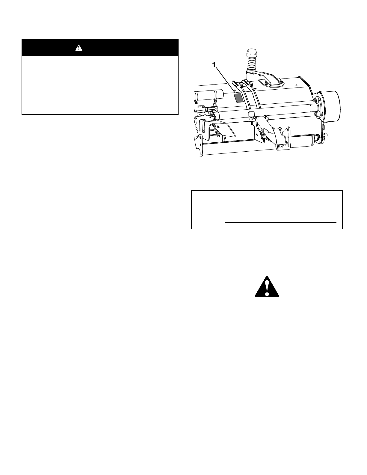
SafetyandInstructionalDecals..........................4
Setup........................................................................6
1PreparingtheMachine.....................................6
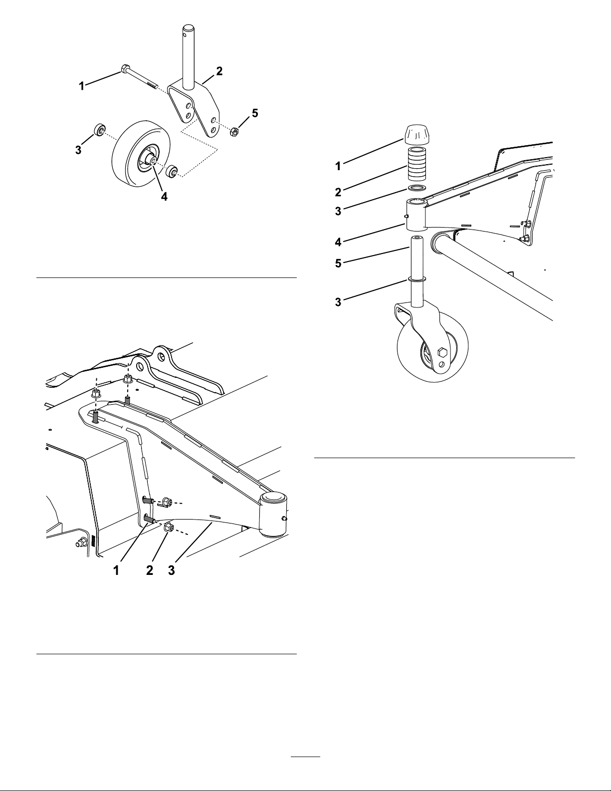
2AssemblingtheCasterArmsandCasters
totheCuttingUnit...........................................7
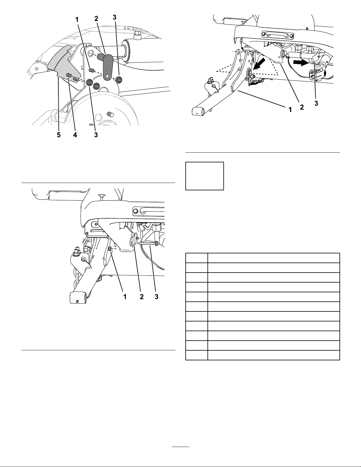
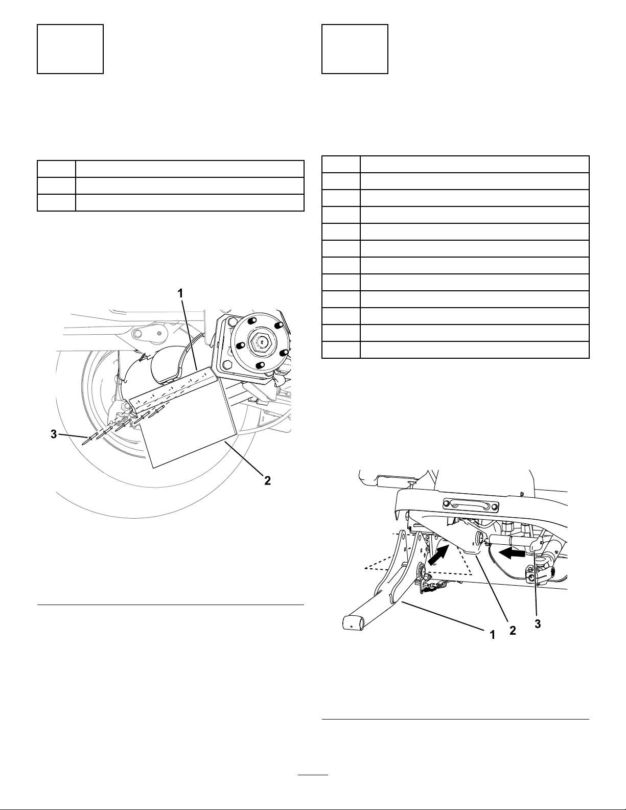
3InstallingtheDebrisGuardtotheFront
Axle.................................................................9
4InstallingtheCuttingUnittothe
Machine..........................................................9
5InstallingthePTOGuard.................................11
6AdjustingtheSensorBracket..........................11
7AdjustingtheWeightTransfer.........................11
8CheckingtheGearboxOil..............................12
9CheckingtheCasterTirePressure.................12
10GreasingtheMachine..................................12
ProductOverview...................................................12
Specications..................................................12
Attachments/Accessories.................................12
Operation................................................................13
CuttingUnitGeneralInformation.......................13
AdjustingtheHeightofCut...............................13
InspectingtheBlades.......................................14
OperatingTips.................................................15
Maintenance...........................................................16
RecommendedMaintenanceSchedule(s)...........16
DailyMaintenanceChecklist.............................17
LubricatingtheCuttingUnit...............................18
CheckingtheLubricantintheGearbox..............19
ChangingtheLubricantintheGearbox.............19
CheckingtheBeltTension................................20
CheckingtheBeltDriveandTaperLock
Hardware......................................................21
RemovingtheCuttingUnitfromthe
Machine........................................................21
ServicingtheBushingsintheCaster
Arms.............................................................22
ServicingtheCasterWheelsand
Bearings........................................................22
CheckingtheBladeBolts..................................23
CheckingtheFrontFlaps..................................23
ClearingaBlockedRotor..................................23
CheckingtheCasterTirePressure...................23
CheckingforRotorVibration.............................23
CheckingtheRotorBearings............................24
SharpeningtheBlades.....................................24
ReplacingtheBlades........................................25
CleaningUndertheCuttingUnit........................25
Storage...................................................................26
Safety
Thismachinehasbeendesignedinaccordancewith
ANSIB71.4andMSD.
GeneralSafety
Thisproductiscapableofamputatinghandsandfeet.
Alwaysfollowallsafetyinstructionstoavoidserious
personalinjury.
•Readandunderstandthecontentsofthis
Operator’sManualbeforestartingthemachine.
•Useyourfullattentionwhileoperatingthe
machine.Donotengageinanyactivitythat
causesdistractions;otherwise,injuryorproperty
damagemayoccur.
•Donotputyourhandsorfeetnearmoving
componentsofthemachine.
•Donotoperatethemachinewithoutallguards
andothersafetyprotectivedevicesinplaceand
functioningproperlyonthemachine.
•Keepclearofanydischargeopening.
•Keepbystandersandchildrenoutoftheoperating
area.Neverallowchildrentooperatethemachine.
•Beforeyouleavetheoperator’sposition,dothe
following:
–Parkthemachineonalevelsurface.
–Lowerthecuttingunit(s).
–Disengagethedrives.
–Engagetheparkingbrake(ifequipped).
–Shutofftheengineandremovethekey.
–Waitforallmovementtostop.
Improperlyusingormaintainingthismachinecan
resultininjury.Toreducethepotentialforinjury,
complywiththesesafetyinstructionsandalways
payattentiontothesafety-alertsymbol,which
meansCaution,Warning,orDanger—personalsafety
instruction.Failuretocomplywiththeseinstructions
mayresultinpersonalinjuryordeath.
3

CuttingUnitSafety
•Thecuttingunitisonlyacompletemachinewhen
installedonatractionunit.Readthetraction
unitOperator’sManualcarefullyforcomplete
instructionsonthesafeuseofthemachine.
•Stopthemachine,removethekey(ifequipped),
lowerthecuttingunit,andwaitforallmovementto
stopbeforeinspectingtheattachmentafterstriking
anobjectorifthereisanabnormalvibrationin
themachine.Makeallnecessaryrepairsbefore
resumingoperation.
•Keepallpartsingoodworkingconditionandall
hardwaretightened.Replaceallwornordamaged
decals.
•Useonlyaccessories,attachments,and
replacementpartsapprovedbyToro.
BladeSafety
Awornordamagedbladecanbreak,andapieceof
thebladecouldbethrowntowardyouorbystanders,
resultinginseriouspersonalinjuryordeath.
•Inspectthebladesperiodicallyforwearordamage.
•Usecarewhencheckingtheblades.Wrapthe
bladesorweargloves,andusecautionwhen
servicingtheblades.Onlyreplaceorsharpenthe
blades.
SafetyandInstructionalDecals
Safetydecalsandinstructionsareeasilyvisibletotheoperatorandarelocatednearanyarea
ofpotentialdanger.Replaceanydecalthatisdamagedormissing.
decal134-3688
134-3688
1.Heightofcut3.Mountingholelocations
2.Donotusethelowermountinghole.
decal117-4979
117-4979
1.Entanglementhazard,belt—keepawayfrommovingparts;
keepallguardsandshieldsinplace.
decal58-6520
58-6520
1.Grease
4

decal111-9648
111-9648
1.Warning—readtheOperator'sManual;torquethenutsto
45N∙m(33ft-lb).
decal120-6604
120-6604
1.Thrownobjecthazard—keepbystandersawayfromthe
machine.
2.Cutting/dismembermenthazardofhand,mower
blade—stayawayfrommovingparts;keepallguardsand
shieldsinplace.
3.Cutting/dismembermenthazardoffoot,mowerblade—stay
awayfrommovingparts;keepallguardsandshieldsin
place.
decal93-9084
93-9084
1.Liftpoint/Tie-downpoint
decal133-8061
133-8061
decal93-6697
93-6697
1.ReadtheOperator's
Manual.
2.AddSAE80w-90(API
GL-5)oilevery50hours.
decal139-6303
139-6303
1.Entanglementhazard—readtheOperator’sManual;stay
awayfrommovingparts;keepallguardsandshieldsin
place.
5

Setup
1
PreparingtheMachine
NoPartsRequired
Procedure
Note:Retainallremovedpartsunlessotherwise
noted.
1.Parkthemachineonalevelsurface,disengage
thePTO,movetheliftarmstothelowest
position,engagetheparkingbrake,shutoffthe
engine,andremovethekey.
2.Waitforallmovementtostopandallowthe
machinetocoolbeforeadjusting,cleaning,
storing,orrepairingit.
3.Ifacuttingunitisequipped,removethecutting
unitfromthemachineliftarms;refertoyour
cuttingunitOperator’sManual.
4.MarkbothhalvesofthePTOshaftwithastraight
linetonotethecorrectorientation,andremove
thefronthalfofthePTOshaft(Figure3).
Note:Supportbothendsoftheshaftand
ensurethatyoudonotdamagethesplinesor
yoke.
g320370
Figure4
1.RearhalfofPTOshaft3.Slideoutthefronthalfof
thePTOshaft
2.Drawastraightlineacross
bothhalvesofthePTO
shafttomarkthecorrect
orientationforassembly.
5.Drilltheexistingholesoutto15/32inchas
showninFigure4.
Important:Theseholesmustbedrilledto
15/32inch;donotuseametricbitasthesize
willnotbeequivalent.
Note:Ensurethatthedrillholesarestraightand
thatnoswarfordebrisfromdrillingispresent
whenyouassemblethehalvesoftheshaft.
g320373
Figure5
1.Drilltheseholesto15/32inch
6.Alignthehalvesoftheshaftusingthemark
madeinstep4andslidefronthalfintotherear
half.
Important:Ensurethatthehalvesof
theshaftareassembledwiththecorrect
orientation;anincorrectlyassembledPTO
shaftmaynotbebalanced,causingvibration
ordamage.
7.Ifliftarmsareinstalledonthetractionunit,
removetheliftarmsasfollows:
A.Raisethefrontofthemachineandremove
thefrontwheelsfromthemachine;referto
yourtractionunitOperator’sManual.
B.Removethe2carriageboltsand2nuts(3/8
inch)thatsecurethesensorbrackettothe
rightliftarm(Figure6).
Note:Manuallyrotatetheliftarmupto
alignitwiththecylinder-rodend.
Note:Ensurethatthesensorbracketdoes
notinterferewiththesensor.
C.Removethe2bolts(3/8x1-1/4inches),2
nuts(3/8inch),and2smallpinsthatsecure
theliftarmstothecylinders(Figure6).
D.Removethenutandboltssecuringthelarge
pinstotheliftarmsasshowninFigure7.
E.Removetheliftarmsandlargepinsfrom
themachineframeFigure8.
6

g300498
Figure6
1.Bolt(3/8x1-1/4inches)4.Carriagebolt
2.Smallpin5.Sensorbracket
3.Nut(3/8inch)
g295767
Figure7
Rightsideshown
1.Nut3.Bolt
2.Largepin
g295790
Figure8
1.Liftarm3.Largepin
2.Machineframe
2
AssemblingtheCaster
ArmsandCasterstothe
CuttingUnit
Partsneededforthisprocedure:
2Castorfork
2Castorbolt
4Bearing
2Bearingspacer
2Largelocknut
2Casterarm
12Carriagebolt(M10)
12Locknut(M10)
2Tensioningcap
14HoCspacers
4Shim
Procedure
1.Assemblethecasterwheelstothecastorfork
asshowninFigure9.
Note:Useonlytheupperaxleshafthole;do
notadjustthepositionofthecasterwheel.
7

g319436
Figure9
1.Castorbolt4.Bearingspacer
2.Castorfork5.Largelocknut
3.Bearing
2.Assembleeachcasterarmtothecuttingunit
with6carriagebolts(M10)and6locknuts(M10)
asshowninFigure10;torquethelocknutsto47
to57N∙m(34to42ft-lb).
g314698
Figure10
Leftsideshown
1.Carriagebolt3.Casterarm
2.Locknut
3.Assemblethecasterstothecuttingunitwitha
shimonbothsidesofthecastershafthubas
showninFigure11.
Note:Youcanadjusttheheight-of-cutsetting
bychangingtheamountofspacersoneither
sideofthecastershafthub;refertoAdjusting
theHeightofCut(page13).
g319438
Figure11
1.Tensioningcap4.Castershafthub
2.HoCspacers5.Casterwheelshaft
3.Shim
4.Ensurethatthedeckislevel;movethedeckto
alevelsurfaceandplacealevelhorizontally
acrossthetopofthedeck.
5.Ifthedeckisnotlevel,positiontheshimsonthe
castershaftaccordinglyuntilitislevel.
8

3
InstallingtheDebrisGuard
totheFrontAxle
Partsneededforthisprocedure:
1Debrisguard
1Bracket
5Rivet
Procedure
Use5rivetstoinstallthebracketanddebrisguardto
thefrontaxle(Figure12).
g312858
Figure12
Leftsideshown
1.Bracket3.Rivet
2.Debrisguard
4
InstallingtheCuttingUnit
totheMachine
Partsneededforthisprocedure:
2Liftarm
2Largepin
2Longbolt(3/8x2-3/4inches)
6Nut(3/8inch)
2Smallpin
2Bolt(3/8x1-1/4inches)
1Sensorbracket
2Carriagebolt(3/8x1-1/4inches)
2PTOBolt(3/8x2inches)
2PTOLocknut(3/8inch)
2Liftarmpin
2Lynchpins
Procedure
1.Raisethefrontofthemachineandremove
thefronttiresfromthemachine;refertoyour
tractionunitOperator’sManual.
2.Installtheliftarmsandlargepinstothemachine
frameFigure13.
g317790
Figure13
Rightsideshown
1.Liftarm3.Largepin
2.Machineframe
3.Securethelargepintotheliftarmusingapair
ofnutsandboltsasshowninFigure14.
9

g317791
Figure14
1.Nut3.Bolt
2.Largepin
4.Secureeachcylinder-rodendtotheeachlift
armswithasmallpins,bolts(3/8x1-1/4inches),
andnut(3/8inch)asshowninFigure15.
Note:Manuallyrotatetheliftarmtoalignitwith
thecylinder-rodend.
5.Securethesensorbrackettotherightliftarm
using2carriageboltsand2nuts(3/8inch)as
showninFigure15.
Note:Ensurethatthesensorbracketdoesnot
interferewiththesensor;referto6Adjustingthe
SensorBracket(page11)ifnecessary.
g300498
Figure15
1.Bolt(3/8x1-1/4inches)4.Carriagebolt
2.Smallpin5.Sensorbracket
3.Nut(3/8inch)
6.Alignthecuttingunitinfrontofthemachine
frameandPTOshaft.
7.InstallthePTOshaftyoketothecuttingunit
gearboxshaftasshowninFigure16.
8.Torquetheboltsto47N∙m(35ft-lb).
Important:ThePTOshaftyokeboltsmust
betightenedtothespeciedtorque.Failure
toproperlytorquetheboltsresultsin
prematurefailureofcriticalparts.
g295791
Figure16
1.Nut2.Bolt
9.Securetheailtotheliftarmsusingtheliftarm
pinsandlynchpins(Figure30).
10

5
InstallingthePTOGuard
Partsneededforthisprocedure:
1PTOguardassembly
2Screw(3/8x3/4inch)
2Washers
Procedure
InstallthePTOguardassemblytothetopofthe
gearboxasshowninFigure17.
g319441
Figure17
1.Screw(3/8x3/4inch)3.Washer
2.PTOguardassembly
6
AdjustingtheSensor
Bracket
NoPartsRequired
Procedure
1.Thesensorandthesensorplateshouldhave
a3.3to3.8mm(0.13to0.15in)clearance
betweenthem.
2.Ifnecessary,loosenthelocknutsthatsecure
theswitchtotheswitchbracketandadjustitso
thatthecorrectclearanceexistsbetweenthe
sensorandthesensorplate.
3.Tightenthesensorlocknutsfrom19to21N·m
(14to16ft-lb).
7
AdjustingtheWeight
Transfer
NoPartsRequired
Procedure
Adjusttheweighttransferoftheattachment;referto
thetractionunitOperator’sManual.
11

8
CheckingtheGearboxOil
NoPartsRequired
Procedure
Ensurethatthegearboxhasthecorrectamountofoil;
refertoCheckingtheLubricantintheGearbox(page
19).
9
CheckingtheCasterTire
Pressure
NoPartsRequired
Procedure
Ensurethatthecastertiresarelledto2to3.5bar(30
to50psi);refertoCheckingtheCasterTirePressure
(page23).
10
GreasingtheMachine
NoPartsRequired
Procedure
Greasethemachinebeforetherstoperation;refer
toLubricatingtheCuttingUnit(page18).Failureto
properlygreasethemachinewillresultinpremature
failureofcriticalparts.
ProductOverview
Specications
Note:Specicationsanddesignaresubjectto
changewithoutnotice.
Width
ofCut1.52m(60inches)
Height
ofCut
Adjustablefrom19to102mm(3/4to4inches)in13
mm(1/2inch)increments
Net
Weight260kg(573lb)
Attachments/Accessories
AselectionofT oroapprovedattachmentsand
accessoriesisavailableforusewiththemachine
toenhanceandexpanditscapabilities.Contact
yourAuthorizedServiceDealerorauthorizedToro
distributororgotowww.T oro.comforalistofall
approvedattachmentsandaccessories.
Toensureoptimumperformanceandcontinuedsafety
certicationofthemachine,useonlygenuineT oro
replacementpartsandaccessories.Replacement
partsandaccessoriesmadebyothermanufacturers
couldbedangerous,andsuchusecouldvoidthe
productwarranty.
12

Operation
CuttingUnitGeneral
Information
Keeptheailbladessharpandingoodconditionto
ensuregoodcuttingperformance,minimumpower
consumption,andgoodqualityofcut.
Thecuttingunitoatstofollowgroundcontours.
Operatethecuttingunitatfullenginespeed.Adjust
theforwardspeedtosuitthegrassconditionsandto
notoverloadthecuttingunit.Thelowertheforward
speed,thebetterthequalityofcutandafter-cut
appearance.
AdjustingtheHeightofCut
Note:Theheightofcutisdeterminedbythe
rearrollerandthefrontcasters.Bladewear,tire
pressure,andbent/damagedcasterarmscanaffect
theheight-of-cutsetting.
g292389
Figure18
Somepartsnotshownforclarity.
1.Heightofcut3.Height-of-cutadjuster
plate
2.Spacer
1.Positionthemachineonalevelsurface,raise
thecuttingunitandsupportitwithjackstands,
shutofftheengine,settheparkingbrake,and
removethekeyfromtheignitionswitch.
2.Refertotheheight-of-cutsettingtableondecal
134-3688(Figure19)forcommonheight-of-cut
settings.
g292390
Figure19
1.Height-of-cutadjuster
platemountingpositions
2.Casterforkheight-of-cut
spacers
3.Tomakesignicantheight-of-cutadjustments,
adjustthepositionoftheheight-of-cutadjuster
plate.Removethenuts,spacers,andbolts
securingtheplate(Figure20).
4.Installtheboltsinthelocationsspeciedin
Figure19forthedesiredheightofcut;torque
thenutsto60N∙m(44ft-lb).
g319475
Figure20
1.Mountinghole"H”5.Mountinghole“A”
2.Mountinghole“L”6.Nut
3.Mountinghole“C”7.Bolt
4.Mountinghole“B”
5.Tomakeprecisionheight-of-cutadjustments,
removetheheight-of-cutcapsfromthefront
castershaftsandadjusttheamountofspacers
oneithersideofthecastershafthub(Figure19).
Note:Spacersplacedabovethecastershaft
hubdecreasetheheightofcut,spacersplaced
belowthehubincreasetheheightofcut.
6.Installtheheight-of-cuttensioningcaps.
13

InspectingtheBlades
ServiceInterval:Every50hours—Inspecttheblades
fordamageandexcessivewear.
Every50hours—Ensurethateachbladeboltis
torquedto45N∙m(33.2ft-lb).
Important:Intheeventthatasinglebladeis
damaged,boththatbladeandthebladeopposite
toitshouldberemovedandreplacedasapairto
maintainbalance.
1.Parkthemachineonalevelsurface,raisethe
cuttingunit,engagetheparkingbrake,shutoff
theengine,andremovethekeyfromtheignition
switch.
2.Supporttheraisedcuttingunitusingjackstands.
3.Inspecteachbladefordamagepayingparticular
attentiontothefasteners,cuttingedge,and
installationhole(Figure21).Replaceall
damagedbladesandfasteners.
g034632
Figure21
1.Cuttingedge2.Installationhole
4.Inspecteachbladeforexcessivewearusingthe
wearline(Figure22).Whenabladeisworn
downtothewearline,replacetheblade.
g034634
Figure22
1.Wearline
5.Ensurethateachbladeboltistorquedto45N∙m
(33.2ft-lb).
6.Gripeachbladeandensurethatthereisnot
morethanatotalof3mm(1/8inch)offree
movementineitherdirectionfromtherotor.If
thereismorethanatotalof3mm(1/8inch)of
freemovement,replacetheblade.
7.Checkeachpairofoppositebladesforaweight
differencebetweenthem.
Note:Eachpairofoppositebladesshouldnot
haveaweightdifferenceofmorethan10g(0.4
oz).
DANGER
Awornordamagedbladecanbreak,anda
pieceofthebladecouldbethrowntowardyou
orbystanders,resultinginseriouspersonal
injuryordeath.
•Inspectthebladesperiodicallyforwearor
damage.
•Replaceawornordamagedblade.
14

OperatingTips
FastThrottleSetting/Ground
Speed
Tomaintainenoughpowerforthemachineandthe
cuttingunitwhilemowing,operatetheengineatthe
fastthrottlepositionandadjustyourgroundspeedfor
theconditions.Decreasethegroundspeedasthe
loadonthecuttingunitincreases.Increasetheground
speedastheloadonthecuttingunitdecreases.
MowingDirection
Alternatemowingdirectiontoavoidmakingrutsin
theturfovertime.Thisalsohelpsdisperseclippings
whichenhancesdecompositionandfertilization.
CuttingSpeed
Toimprovecutquality,useaslowergroundspeed.
AvoidCuttingTooLow
Ifthecuttingwidthofthecuttingunitiswiderthanthe
moweryoupreviouslyused,raisethecuttingheightto
ensurethatuneventurfisnotcuttooshort.
SelecttheProperHeight-of-Cut
SettingtoSuitConditions
Removeapproximately1inch(25mm)orno
morethan1/3ofthegrassbladewhencutting.In
exceptionallylushanddensegrass,youmayhave
toslowdowntheforwardspeedand/orraisethe
height-of-cuttothenexthighersetting.
LongGrass
Ifthegrassiseverallowedtogrowslightlylongerthan
normal,orifitcontainsahighdegreeofmoisture,
raisethecuttingheighthigherthantheusualsetting
andcutthegrass.Then,cutthegrassagainusing
thelower,normalsetting.
KeeptheCuttingUnitClean
Cleanclippingsanddirtfromtheundersideofthe
cuttingunitaftereachuse.Ifgrassanddirtbuildup
insidethecuttingunit,cuttingqualitywilleventually
becomeunsatisfactory.
Toreducetheriskofrehazard,keeptheengine,
mufer,batterycompartment,parkingbrake,cutting
unit,andfuelstoragecompartmentfreeofgrass,
leaves,orexcessivegrease.Cleanupanyspilledoil
orfuel.
BladeMaintenance
•Maintainsharpbladesthroughoutthecutting
season;asharpbladecutscleanlywithouttearing
orshreddingthegrassblades.Tearingand
shreddingturnsgrassbrownattheedges,which
slowsgrowthandincreasesthechanceofdisease.
•Checkthebladesdailyforsharpnessandfor
anywearordamage.Sharpenthebladesas
necessary.
•Ifabladeisdamagedorworn,replaceit
immediatelywithagenuineTororeplacement
blade.RefertoReplacingtheBlades(page25).
15

Maintenance
RecommendedMaintenanceSchedule(s)
MaintenanceService
IntervalMaintenanceProcedure
Aftertherst2hours•Tightenthecasterwheelnuts.
Aftertherst10hours•Tightenthecasterwheelnuts.
Beforeeachuseordaily
•Checktheheight-of-cutsetting.
•Inspecttheailrotorsandbladesfordamage,cracks,andloosefasteners.Replace
anydamagedorcrackedparts.
•Greasethecuttingunit(greasethemimmediatelyaftereverywashingregardlessof
theintervallisted).
•Checkthefrontaps.
•Checkforanyunusualvibrationoftherotor.
•Cleanthecuttingunit.
Every50hours
•Inspectthebladesfordamageandexcessivewear.
•Ensurethateachbladeboltistorquedto45N∙m(33.2ft-lb).
•Checkthegearboxlubricant.
•Tightenthecasterwheelnuts.
•Checkthebladebolts.
•Ensurethatthecastertiresareatthecorrecttirepressure.
•Checkforexcessiveplayintherotorbearings.
Every250hours
•Checkthebelttension.
•Ensurethatthebeltdriveandtaper-lockbushingsetscrewsaretightenedtothe
correcttorque.
Every400hours•Changethegearboxlubricant.
Yearly•Replacetheblades.
16

CAUTION
Ifyouleavethekeyintheignitionswitch,someonecouldaccidentlystarttheengineand
seriouslyinjureyouorotherbystanders.
Removethekeyfromtheignitionbeforeyoudoanymaintenance.
DailyMaintenanceChecklist
Duplicatethispageforroutineuse.
Fortheweekof: MaintenanceCheckItem
Mon.Tues.Wed.Thurs.Fri.Sat.Sun.
Checktheconditionofthe
blades.
Lubricateallthegrease
ttings.1
Touch-updamagedpaint.
1.Immediatelyaftereverywashing,regardlessoftheintervallisted.
NotationforAreasofConcern
Inspectionperformedby:
ItemDateInformation
17

CheckingtheLubricantin
theGearbox
ServiceInterval:Every50hours
Thegearboxisdesignedtooperateoneither
petroleumorsyntheticSAE80W–90gearlube.
Althoughthegearboxisshippedwithlubricantfrom
thefactory,checkthelevelbeforeoperatingthecutting
unit.Thegearboxcapacityis0.33L(11.15oz).
1.Parkthemachineonalevelsurface,lowerthe
cuttingunit,engagetheparkingbrake,shutoff
theengine,andremovethekey.
2.Removethebreatherplugfromthetopof
thegearbox(Figure24)andensurethatthe
lubricantisbetweenthellmarksonthelower
partofthebreatherplug.Ifthelubricantlevel
islow,addenoughlubricantuntilthelevelis
betweenthemarks.
g313145
Figure24
1.Oillevelllmarksonbreatherplug
3.Installthebreatherplugandtorqueitto9N∙m
(84in-lb).
ChangingtheLubricantin
theGearbox
ServiceInterval:Every400hours
1.Parkthemachineonalevelsurface,lowerthe
cuttingunit,engagetheparkingbrake,shutoff
theengine,andremovethekey.
2.Placeapanbeneaththedrainplugonthe
gearbox(Figure25).
3.Removethedrainplugonthelowerleftsideof
thegearboxanddraintheuid(Figure25).
g313477
Figure25
1.Drainplug
4.Installthedrainplugandtorqueto20to27N∙m
(15to20ft-lb).
5.Removethebreatherplugfromthetopofthe
gearbox.
6.Fillthegearboxwiththecorrectgearlube,
checkingperiodicallythatthelubricantis
betweenthelowerllmarksonthebreather
plug;refertoCheckingtheLubricantinthe
Gearbox(page19).
7.Whenthelubricantisbetweenthelowerll
marksonthebreatherplug,installthebreather
plugandtorqueitto9N∙m(84in-lb).
19

CheckingtheBeltTension
ServiceInterval:Every250hours
1.Parkthemachineonalevelsurface,lowerthe
cuttingunit,engagetheparkingbrake,shutoff
theengine,andremovethekey.
2.Loosenthe4captiveboltsthatsecurethetop
andbottomofthebeltcovertothemachine
(Figure26).
g319558
Figure26
1.Beltcovercaptivebolts
g320055
Figure27
1.Idlerpulleynut2.Idlerpulleypostnut
3.Loosen,butdonotremove,theidlerpulleynut
(Figure27).
Note:T oloosentheidlerpulleynut,youwill
needtoholdtheboltthatsecuresitinplaceon
theinsideofthedeck.
4.Adjustthenutontheidlerpulleyposttotension
thebelt(Figure27).
5.Pushdownonthebelttocheckthetensionas
follows(Figure28):
•Foranewbelt,youshouldbeabletopush
thebeltdown5mm(1/5inch)using6.0to
6.5kg(13.2to14.3lb)offorce.
•Forausedbelt,youshouldbeabletopush
thebeltdown5mm(1/5inch)using5.1to
5.6kg(11.2to12.3lb)offorce.
g313475
Figure28
1.Beltwithoutforce2.Beltdeected5mm(0.2
inches)
Note:Useasinglebarreltensionmeterto
measurethetension.
6.Adjustthenutontheidlerpulleypostas
necessarytotightenorloosenthebelt.
7.Rotatetherotormanuallyacoupleofturnsand
checkthebelttensionagain;ifthetensionis
incorrect,checkandadjustuntilitiscorrect.
8.Tightentheidlerpulleynut;torqueto47to57
N∙m(34to42ft-lb).
9.Installthebeltcover(Figure26).
20
This manual suits for next models
1
Table of contents
Other Toro Lawn Mower manuals

Toro
Toro 74142TE User manual

Toro
Toro Z Master 74941CP User manual

Toro
Toro REELMASTER 5010 Series User manual

Toro
Toro 72071 Manual

Toro
Toro 71242 User manual

Toro
Toro 20323 User manual

Toro
Toro Groundsmaster 4500-D User manual

Toro
Toro TimeMaster Series User manual

Toro
Toro 22192 User manual

Toro
Toro 3318 User manual

Toro
Toro 30530 User manual

Toro
Toro 30292 User manual

Toro
Toro TimeCutter MR4275T User manual

Toro
Toro Super Recycler 20797 User manual

Toro
Toro 74570 User manual

Toro
Toro Titan 75303 User manual

Toro
Toro 30845 User manual

Toro
Toro Recycler 22284 User manual

Toro
Toro groundsmaster 455-D User manual

Toro
Toro Super Recycler 20792 User manual