Toro Super Recycler 20792 User manual

Form No. 3356-758 Rev A
53cm Super Recycler® Lawn Mower
Model No. 20792 —Serial No. 270000001 and Up
Operator's Manual
Introduction
R ead this infor mation carefully to lear n ho w to operate and
maintain y our product properly and to a v oid injur y and
product damag e . Y ou are responsible for operating the
product properly and safely .
Y ou ma y contact T oro directly at www .T oro .com for
product and accessor y infor mation, help finding a dealer ,
or to register y our product.
W henev er y ou need ser vice , g en uine T oro par ts , or
additional infor mation, contact an A uthorized Ser vice
Dealer or T oro Customer Ser vice and ha v e the model and
serial n umbers of y our product ready . Figure 1 identifies the
location of the model and serial n umbers on the product.
Figure 1
1. Model and serial number plate
W rite the product model and serial n umbers in the space
belo w:
Model No.
Serial No.
T his man ual identifies potential hazards and has safety
messag es identified b y the safety aler t symbol ( Figure 2 ),
whic h signals a hazard that ma y cause serious injur y or
death if y ou do not follo w the recommended precautions .
Figure 2
1. Safety alert symbol
T his man ual uses 2 w ords to highlight infor mation.
Impor tant calls attention to special mec hanical infor mation
and Note emphasizes g eneral infor mation w or th y of special
attention.
T his spark ignition system complies with Canadian
ICES-002
F or models with stated engine horse po w er , the g ross
horse po w er of the engine w as laborator y rated b y the engine
man ufacturer in accordance with SAE J1940. As configured
to meet safety , emission, and operating requirements , the
actual engine horse po w er on this class of la wn mo w er will
be significantly lo w er .
Safety
Impr oper l y using or maintaining this mo w er can r esult
in injur y . T o r educe the potential f or injur y , compl y
with these safety instr uctions.
T oro designed and tested this mo w er for reasonably safe
ser vice; ho w ev er , failure to comply with the follo wing
instr uctions ma y result in personal injur y .
T o ensur e maximum safety , best perf or mance, and
to gain kno wledge of the pr oduct, it is essential that
y ou and an y other operator of the mo w er r ead and
under stand the contents of this man ual bef or e the
engine is ev er star ted. P ay par ticular attention to the
safety aler t symbol ( Figur e 2 ) which means Caution,
W ar ning , or Danger—“per sonal safety instr uction.”
R ead and under stand the instr uction because it has to
do with safety . F ailur e to compl y with the instr uction
may r esult in per sonal injur y .
General Lawn Mower Safety
T he follo wing instr uctions ha v e been adapted from the ISO
standard 5395.
T his cutting mac hine is capable of amputating hands and
feet and thro wing objects . F ailure to obser v e the follo wing
safety instr uctions could result in serious injur y or death.
Training
•R ead the instr uctions carefully . Be familiar with the
controls and the proper use of the equipment.
•Nev er allo w c hildren or people unfamiliar with these
instr uctions to use the mo w er . Local regulations can
restrict the ag e of the operator .
© 2006—The Toro® Company8111 Lyndale Avenue SouthBloomington, MN 55420
Register at www.Toro.com. Original Instructions (EN)Printed in the USA.All Rights Reserved

•K ee p in mind that the operator or user is responsible
for accidents or hazards occur ring to other people or
their proper ty .
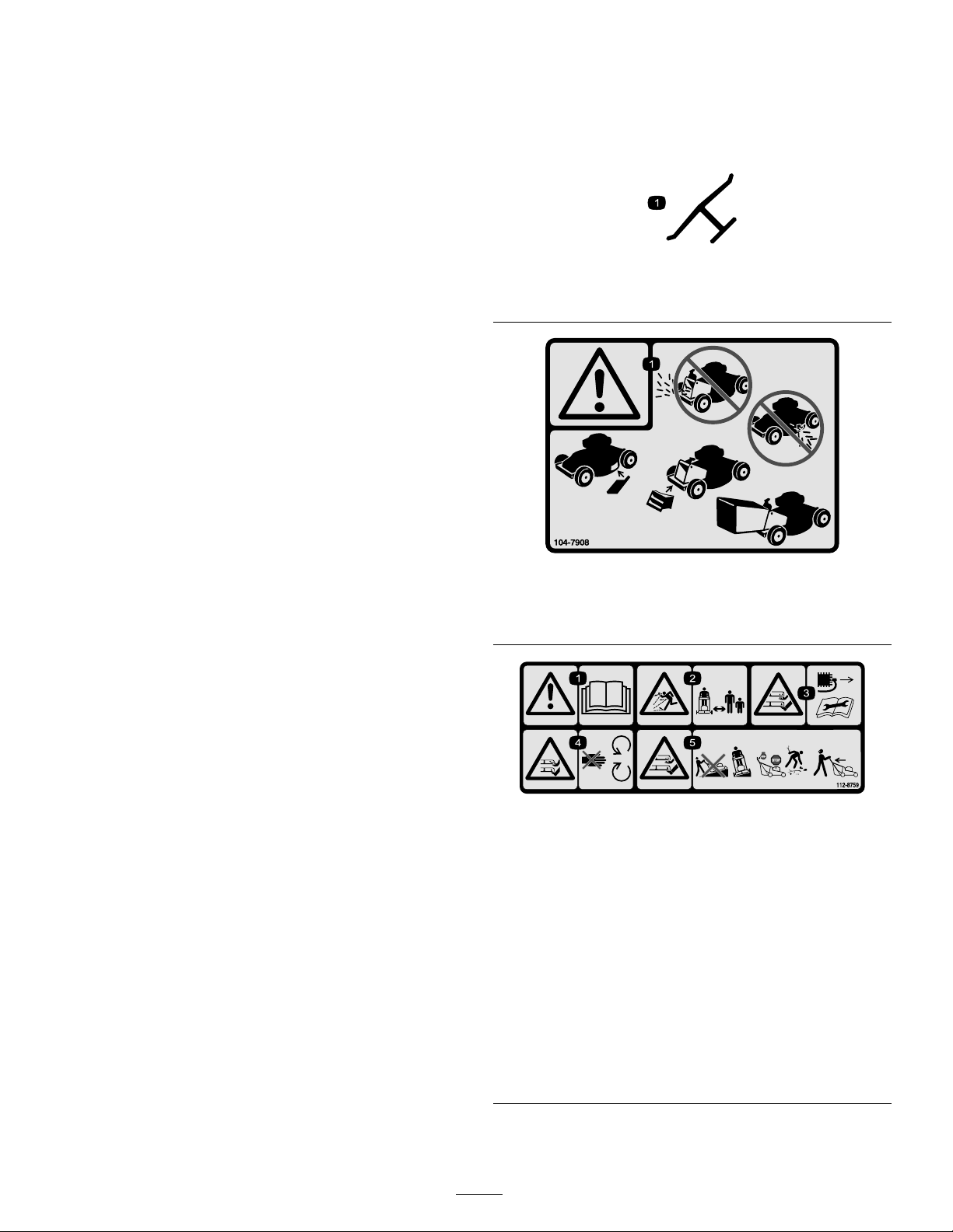
•Understand explanations for all pictog rams used on the
mo w er or in the instr uctions .
Gasoline
W ARNING -Gasoline is highly flammable . T ak e the
follo wing precautions .
•Store fuel in containers specifically designed for this
pur pose .
•R efuel outdoors only and do not smok e while refueling .
•Add fuel before star ting the engine . Nev er remo v e the
cap of the fuel tank or ad g asoline while the engine is
r unning or when the engine is hot.
•If g asoline is spilled, do not attempt to star t the engine
but mo v e the mo w er a w a y from the area of spillag e
and a v oid creating any source of ignition until g asoline
v apors ha v e dissipated.
•R e place all fuel tank and container caps securely .
Preparation
•W hile mo wing, alw a ys w ear substantial footw ear and
long trousers . Do not operate the equipment when
barefoot or w earing open sandals .
•T horoughly inspect the area where the equipment is to
be used and remo v e all stones , stic ks , wires , bones and
other foreign objects .
•Before using, alw a ys visually inspect to see that guards ,
and safety devices , suc h as deflectors and/or g rass
catc hers , are in place and w orking cor rectly .
•Before using, alw a ys visually inspect to see that the
blades , blade bolts and cutter assembly are not w or n or
damag ed. R e place w or n or damag ed blades and bolts
in sets to preser v e balance .
Starting
•Diseng ag e all blade and dri v e clutc hes and shift into
neutral before star ting the engine .
•Do not tilt mo w er when star ting the engine or switc hing
on the motor , unless the mo w er has to be tilted for
star ting . In this case , do not tilt it more than absolutely
necessar y and lift only the par t, whic h is a w a y from the
operator .
•Star t the engine or switc h on the motor carefully
according to instr uctions and with feet w ell a w a y from
the blade(s) and not in front of the disc harg e c hute .
Operation
•Nev er mo w while people , especially c hildren, or pets
are nearb y .
•Mo w only in da ylight or in g ood ar tificial light.
•Sta y aler t for holes in the ter rain and other hidden
hazards .
•Do not put hands or feet near or under rotating par ts .
K ee p clear of the disc harg e opening at all times .
•Nev er pic k up or car r y a la wn mo w er while the engine
is r unning .
•Use extreme caution when rev ersing or pulling a
pedestrian controlled la wn mo w er to w ards y ou.
•W alk, nev er r un.
•Slopes:
– Do not mo w ex cessi v ely stee p slopes .
– Ex ercise extreme caution when on slopes .
– Mo w across the face of slopes , nev er up and
do wn and ex ercise extreme caution when c hanging
direction on slopes .
– Alw a ys be sure of y our footing on slopes .
•Use lo w throttle settings when eng aging the
traction-clutc h, especially in high g ears . R educe speed
on slopes and in shar p tur ns to prev ent o v er tur ning or
loss of control.
•Stop the blade if the la wn mo w er has to be tilted for
transpor tation when crossing surfaces other than g rass
and when transpor ting the la wn mo w er to and from
the area to be mo w ed.
•Do not operate the engine in a confined space where
dang erous carbon mono xide fumes can collect.
•Stop the engine
– whenev er y ou lea v e the la wn mo w er .
– before refueling .
– before remo ving the g rass catc her .
– before making height adjustment unless adjustment
can be made from the operator’ s position.
•Stop the engine and disconnect the spark-plug wire .
– before clearing bloc kag es or unclog ging c hute .
– before c hec king, cleaning or w orking on the la wn
mo w er .
– after striking a foreign object, inspect the la wn
mo w er for damag e and mak e re pairs before
restar ting and operating the la wn mo w er .
– if la wn mo w er star ts to vibrate abnor mally (c hec k
immediately).
•W atc h out for traffic when crossing or near roadw a ys .
Maintenance and Storage
•K ee p all n uts , bolts and screws tight to be sure the
equipment is in safe w orking condition.
•Do not use pressure cleaning equipment on mac hine .
2

•Nev er store the equipment with g asoline in the tank
and inside a building where fumes can reac h an open
flame or spark.
•Allo w the engine to cool before storing in any enclosure .
•T o reduce the fire hazard, k ee p the engine , silencer ,
batter y compar tment and g asoline storag e area free of
g rass , lea v es , or ex cessi v e g rease .
•Chec k g rass catc her components and the disc harg e
guard frequently and re place with man ufacturer’ s
recommended par ts , when necessar y .
•R e place w or n or damag ed par ts for safety .
•R e place faulty silencers .
•If the fuel tank has to be drained, do this out-doors .
•Do not c hang e the engine g o v er nor settings or
o v erspeed the engine . Operating an engine at ex cessi v e
speed can increase the hazard of personal injur y .
•On m ultibladed la wn mo w ers , tak e care as rotating one
blade ma y cause others to rotate .
•Be careful during adjustment of the la wn mo w er to
prev ent entrapment of the fing ers betw een mo ving
blades and fix ed par ts of the la wn mo w er .
•T o ensur e the best perf or mance and safety ,
purchase onl y gen uine T or o r eplacement par ts
and accessories. Do not use will fit par ts and
accessories; they may cause a safety hazard.
Sound Pressure
T his unit has an equi v alent contin uous A-w eighted sound
pressure lev el at the operator ear of 89 dB A, based on
measurements of identical mac hines per EN 11094 and
EN 836.
Sound Power
T his unit has an equi v alent contin uous A-w eighted sound
po w er lev el of 98 dB A, based on measurements of identical
mac hines per EN 11094.
Vibration, Hand/arm
T his unit does not ex ceed a hand/ar m vibration lev el of
4.7 m/s
2
, based on measurements of identical mac hines
per EN 1033.
Safety and Instructional Decals
Important: Safety and instr uction decals ar e located
near ar eas of potential danger . R eplace dama ged
decals.
Manufacturer’s Mark
1. Indicates the blade is identied as a part from the original machinemanufacturer.
104-7908
1. Warning—do not operate the mower without the rear dischargeplug or bag in place; do not operate the mower without the sidedischarge cover or deector in place.
112-8759
1. Warning—read the Operator’sManual.
4. Cutting/dismemberment
hazard of hand or foot,mower blade—stay away frommoving parts.2. Thrown object hazard—keepbystanders a safe distancefrom the machine.
5. Cutting/dismemberment
hazard of hand or foot,mower blade—do not operateup and down slopes; operateside to side on slopes; stopthe engine before leaving theoperating position; and lookbehind you when backing.3. Cutting/dismemberment
hazard of hand or foot,mower blade—remove thewire from the spark plug, andread the instructions beforeservicing or performingmaintenance.
3

112-8760
1. Thrown object hazard—stay a safe distance from the machine.2. Cutting/dismemberment of hand or foot—stay away from movingparts.
112-8867
1. Lock 2. Unlock
Setup
Important: R emo v e and discard the pr otecti v e
plastic sheet that co v er s the engine.
1. Assembling and Unfoldingthe Handle
Assembling and unf olding the handle impr oper l y
can dama ge the ca bles, causing an unsafe operating
condition.
•Do not dama ge the ca bles when assembling and
unf olding the handle. Ensur e that y ou do not get
the ca bles caught betw een the handle halv es and
that they r un to the inside of the handles.
•If a ca ble is dama ged, contact an Authoriz ed
Ser vice Dealer .
1. R emo v e the upper handle knobs and bolts from the
upper handle ends .
2. Carefully mo v e the upper handle forw ard and place the
ends o v er the lo w er handle so they are in line and nest
tog ether; ( Figure 3 ).
Figure 3
3. Install the bolts and upper handle knobs with the knobs
on the outside of the handle , tightening the knobs as
tight as y ou can ( Figure 4 ).
Figure 4
4. R otate the handle rearw ard ( Figure 5 ).
4

Figure 5
5. Attac h the handle brac k ets ( Figure 6 ) to the lo w er
handle sides .
Figure 6
1. Handle bracket (2)
2. Filling the Engine with Oil
Y our mo w er does not come with oil in the engine .
1. R emo v e the dipstic k ( Figure 7 ).
Figure 7
2. Slo wl y pour oil into the oil fill tube until the oil lev el
reac hes the Full line on the dipstic k ( Figure 7 ). Do not
o v erfill. (Max. fill: 20 oz. (0.59 l), type: SAE 30W
deterg ent oil with an API ser vice classification of SF ,
SG , SH, SJ , SL, or higher .)
3. Install the dipstic k securely .
Important: Change the engine oil after the fir st 5
operating hour s ; change it y ear l y ther eafter . R efer
to Changing the Engine Oil.
5

Product Overview
Figure 8
1. Upper handle
8. Primer2. Recoil start handle 9. Spark plug3. Handle knob (4) 10. Cutting height lever (4)4. Lower rope guide
11. Washout port (not shown)5. Fuel tank cap 12. Oil ll/Dipstick6. Side discharge 13. Blade control bar7. Air lter
Figure 9
1. Grass bag
3. Rear discharge plug (installed)2. Side discharge chute
Operation
Filling the Fuel Tank
Gasoline is extr emel y flamma ble and explosi v e. A
fir e or explosion fr om gasoline can bur n y ou and
other s.
•T o pr ev ent a static charge fr om igniting the
gasoline, place the container and/or mo w er
dir ectl y on the g r ound bef or e filling , not in a
v ehicle or on an object.
•Fill the tank outdoor s when the engine is cold.
W ipe up spills.
•Do not handle gasoline when smoking or ar ound
an open flame or spar ks.
•Stor e gasoline in an appr o v ed fuel container , out
of the r each of childr en.
Fill the fuel tank with fresh unleaded regular g asoline from
a major name-brand ser vice station ( Figure 10 ).
Important: T o r educe star ting pr oblems, add fuel
sta biliz er to the fuel all season, mixing it with gasoline
less than 30 days old.
Figure 10
6

Checking the Engine Oil Level1. R emo v e the dipstic k, wipe it clean, and fully install the
dipstic k ( Figure 11 ).
Figure 11
2. R emo v e the dipstic k and c hec k the oil lev el ( Figure 11 ).
If the oil lev el is belo w the Add mark on the dipstic k,
slo wl y pour oil into the oil fill tube to raise the oil lev el
to the Full mark on the dipstic k. Do not o v erfill. (Max.
fill: 20 oz. (0.59 l), type: SAE 30W deterg ent oil with
an API ser vice classification of SF , SG , SH, SJ , SL, or
higher .)
3. Install the dipstic k.
Adjusting the Cutting Height
Adjusting the cutting height may bring y ou into
contact with the mo ving blade, causing serious
injur y .
•Stop the engine and w ait f or all mo ving par ts to
stop .
•Do not put y our finger s under the housing when
adjusting the cutting height.
If the engine has been r unning , the muf fler will be
hot and can sev er el y bur n y ou. K eep a w ay fr om the
hot muf fler .
Adjust the cutting height as desired. Set all four wheels to
the same height.
Note: T o raise the mo w er , mo v e all 4 cutting height lev ers
forw ard; to lo w er the mo w er , mo v e them all rearw ard
( Figure 12 ).
Figure 12
Adjusting the Handle Height
Y ou ma y raise or lo w er the handle to a position comfor table
for y ou.
1. R emo v e the lo w er handle knobs that attac h the handle
brac k ets to the lo w er handle ends ( Figure 13 ).
Figure 13
2. Inser t the bolt through the hole in eac h of the handle
brac k ets that sets the handle to the desired position
( Figure 14 ).
Figure 14
1. Highest position
3. Lowest position2. Middle position (eitherhole)
3. Install the lo w er handle knobs and tighten the knobs as
tight as y ou can b y hand ( Figure 15 ).
7

Figure 15
Starting the Engine1. Fir mly push in the primer 3 times with y our thumb ,
holding the primer in for a second before releasing it
eac h time ( Figure 16 ).
Figure 16
Note: If the air temperature is belo w 55°F (13°C),
fir mly push the primer in 5 times .
2. Hold the blade control bar ag ainst the handle ( Figure
17 ).
Figure 17
3. Pull the recoil star ter ( Figure 18 ).
Figure 18
4. If the mo w er does not star t in 1 or 2 pulls , press the
primer button 1 or 2 times and tr y star ting it ag ain.
Note: If the mo w er still does not star t, contact an
A uthorized Ser vice Dealer .
Using the Self-propel Drive
T o operate the self-propel dri v e , simply w alk with y our
hands on the upper handle and y our elbo ws at y our sides ,
and the mo w er will automatically k ee p pace with y ou.
Figure 19
Stopping the Engine1. R elease the blade control bar ( Figure 20 ).
Figure 20
2. W hen the engine stops , remo v e the ignition k ey when
y ou lea v e the mo w er .
Important: W hen y ou r elease the blade contr ol
bar , both the engine and blade should stop within
3 seconds. If they do not stop pr oper l y , stop
using y our mo w er immediatel y and contact an
Authoriz ed Ser vice Dealer .
8

Recycling the Clippings
Y our mo w er comes from the factor y ready to recycle the
g rass and leaf clippings bac k into the la wn.
If the g rass bag is on the mo w er , remo v e it (refer to
R emo ving the Grass Bag) before recycling the clippings . If
the side disc harg e c hute is on the mo w er , remo v e it and
loc k the side disc harg e door (refer to R emo ving the Side
Disc harg e Chute) before recycling the clippings .
Important: Ensur e that the r ear discharge plug is in
place bef or e y ou r ecy cle the clippings ( Figur e 21 ).
Figure 21
Bagging the Clippings
Use the g rass bag when y ou w ant to collect g rass and leaf
clippings from the la wn.
A w or n g rass ba g could allo w small stones and
other similar de bris to be thr o wn in the operator’ s or
bystander’ s dir ection and r esult in serious per sonal
injur y or death to the operator or bystander s.
Check the g rass ba g fr equentl y . If it is dama ged,
install a new T or o r eplacement ba g .
If the side disc harg e c hute is on the mo w er , remo v e it and
loc k the side disc harg e door (refer to R emo ving the Side
Disc harg e Chute) before bag ging the clippings .
T he blade is shar p; contacting the blade can r esult
in serious per sonal injur y .
Stop the engine and w ait f or all mo ving par ts to stop
bef or e lea ving the operating position.
Installing the Grass Bag
1. Raise and hold up the rear door ( Figure 22 ).
Figure 22
2. R emo v e the rear disc harg e plug ( Figure 22 ).
3. R oute the star ter rope around the lo w er rope guide
( Figure 23 ).
Figure 23
Note: T he lo w er rope guide releases the star ter rope
when y ou pull the recoil star t handle .
4. Install the bag onto the door rod ( Figure 24 ).
9

Figure 24
5. Lo w er the rear door ( Figure 25 ).
Figure 25
Removing the Grass Bag
T o remo v e the bag, rev erse the ste ps abo v e .
Side-discharging the Clippings
Use the side disc harg e for cutting v er y tall g rass .
If the bag is on the mo w er , remo v e it and inser t the rear
disc harg e plug (refer to R emo ving the Grass Bag) before
side-disc harging the clippings .
Important: Ensur e that the r ear discharge plug is in
place bef or e y ou r ecy cle the clippings ( Figur e 26 ).
Figure 26
T he blade is shar p; contacting the blade can r esult
in serious per sonal injur y .
Stop the engine and w ait f or all mo ving par ts to stop
bef or e lea ving the operating position.
Installing the Side Discharge Chute
1. Unloc k the side disc harg e door ( Figure 27 ).
Figure 27
2. Lift open the side disc harg e door ( Figure 28 ).
Figure 28
3. Install the side disc harg e c hute and close the door onto
the c hute ( Figure 29 ).
Figure 29
10

Removing the Side Discharge Chute
T o remo v e the side disc harg e c hute , rev erse the ste ps abo v e .
Important: Lock the side discharge door after y ou
close it ( Figur e 30 ).
Figure 30
Operating Tips
General Mowing Tips
•Clear the area of stic ks , stones , wire , branc hes , and
other debris that the blade could hit.
•A v oid striking solid objects with the blade . Nev er
deliberately mo w o v er any object.
•If the mo w er strik es an object or star ts to vibrate ,
immediately stop the engine , disconnect the wire from
the spark plug, and examine the mo w er for damag e .
•F or best perfor mance , install a new blade before the
cutting season begins .
•R e place the blade when necessar y with a T oro
re placement blade .
Cutting Grass
•Cut only about a third of the g rass blade at a time . Do
not cut belo w the 2-inc h (51 mm) setting unless the
g rass is sparse or it is late fall when g rass g ro wth begins
to slo w do wn. R efer to Adjusting the Cutting Height.
•W hen cutting g rass o v er 6 inc hes (15 cm) tall, mo w
at the highest cutting height setting and w alk slo w er;
then mo w ag ain at a lo w er setting for the best la wn
appearance . If the g rass is too long, the mo w er ma y
plug and cause the engine to stall.
•Mo w only dr y g rass or lea v es . W et g rass and lea v es tend
to clump on the yard and can cause the mo w er to plug
or the engine to stall.
W et g rass or lea v es can cause serious injur y if
y ou slip and contact the blade. Mo w onl y in dr y
conditions.
•Alter nate the mo wing direction. T his helps disperse the
clippings o v er the la wn for ev en fer tilization.
•If the finished la wn appearance is unsatisfactor y , tr y one
or more of the follo wing:
– R e place the blade or ha v e it shar pened.
– W alk at a slo w er pace while mo wing .
– Raise the cutting height on y our mo w er .
– Cut the g rass more frequently .
– Ov erlap cutting sw aths instead of cutting a full
sw ath with eac h pass .
– Set the cutting height on the front wheels one notc h
lo w er than the rear wheels . F or example , set the
front wheels at 2-1/4 inc hes (60 mm) and the rear
wheels at 2-3/4 inc hes (70 mm).
Cutting Leaves
•After cutting the la wn, ensure that half of the la wn
sho ws through the cut leaf co v er . Y ou ma y need to
mak e more than one pass o v er the lea v es .
•If there are more than 5 inc hes (13 cm) of lea v es on the
la wn, set the front cutting height one or tw o notc hes
higher than the rear cutting height.
•Slo w do wn y our mo wing speed if the mo w er does not
cut the lea v es finely enough.
11

Maintenance
Note: Deter mine the left and right sides of the mac hine from the nor mal operating position.
Recommended Maintenance Schedule(s)
Maintenance ServiceInterval
Maintenance Procedure
After the rst 5 operating
hours
• Change the engine oil.
Before each use or daily
• Check the engine oil level.• Ensure that the engine stops within 3 seconds after releasing the blade controlbar.
• Clean grass clippings and dirt from under the mower.
Every 25 hours
• Lubricate the rear wheel gears.• Replace the blade or have it sharpened (more frequently if the edge dulls quickly).
Every 50 hours
• Change the engine oil.
Every 100 hours
• Clean the cooling system (refer to your engine owner’s manual).• Replace the spark plug (refer to your engine owner’s manual).
Before storage
• Empty the fuel tank before repairs as directed and before annual storage.
Yearly
• Replace the air lter (more frequently in dusty operating conditions).• Check the spark plug (refer to your engine owner’s manual).• Refer to your Engine Operator’s Manual for any additional yearly maintenanceprocedures.
Important: R efer to y our Engine Operator’ s Man ual f or additional maintenance pr ocedur es.
Preparing for Maintenance1. Stop the engine and w ait for all mo ving par ts to stop .
2. Disconnect the spark plug wire from the spark plug
( Figure 31 ) before perfor ming any maintenance
procedure .
Figure 31
3. After perfor ming the maintenance procedure(s),
connect the spark plug wire to the spark plug .
Important: Bef or e tipping the mo w er to change
the oil or r eplace the blade, allo w the fuel tank to
r un dr y thr ough nor mal usa ge. If y ou must tip the
mo w er prior to r unning out of fuel, use a hand fuel
pump to r emo v e the fuel. Al w ays tip the mo w er
onto its side with the air filter up .
Tipping the mo w er may cause the fuel to leak.
Gasoline is flamma ble, explosi v e and can cause
per sonal injur y .
R un the engine dr y or r emo v e the gasoline with a
hand pump; nev er siphon.
Replacing the Air Filter
R e place the air filter yearly; re place it more frequently in
dusty operating conditions .
1. P erfor m the pre-maintenance procedures; refer to
Pre paring for Maintenance .
2. Use a screw dri v er to open the air filter co v er ( Figure
32 ).
12

Figure 32
3. R e place the air filter .
4. Install the co v er ( Figure 33 ).
Figure 33
Changing the Engine Oil
Change the engine oil after the fir st 5 operating hour s ;
c hang e it yearly thereafter .
R un the engine a few min utes before c hanging the oil
to w ar m it. W ar m oil flo ws better and car ries more
contaminants .
1. P erfor m the pre-maintenance procedures; refer to
Pre paring for Maintenance .
2. R emo v e the dipstic k ( Figure 34 ).
Figure 34
3. Tip the mo w er onto its side , with the air filter up , to
drain the used oil out through the oil fill tube ( Figure
35 ).
Figure 35
4. Slo wl y pour oil into the oil fill tube until the oil lev el
reac hes the Full line on the dipstic k ( Figure 36 ). Do
not o v erfill. (Max. fill: 20 oz. (0.59 l), type: SAE 30W
deterg ent oil with an API ser vice classification of SF ,
SG , SH, SJ , SL, or higher .)
Figure 36
5. Install the dipstic k securely .
6. Dispose of the used oil properly at a local recycling
center .
Lubricating the Wheel Gears
Lubricate eac h r ear wheel with g rease yearly .
1. Wipe the g rease fittings just inside the rear wheels with
a clean rag ( Figure 37 ).
Figure 37
2. Install a g rease gun onto eac h fitting and g ently apply 2
or 3 pumps of #2 m ulti-pur pose lithium-base g rease .
13

Replacing the Blade
Important: Y ou will need a torque wr ench to install
the blade pr oper l y . If y ou do not ha v e a torque wr ench
or ar e uncomf or ta ble perf or ming this pr ocedur e,
contact an Authoriz ed Ser vice Dealer .
Examine the blade whenev er y ou r un out of g asoline . If the
blade is damag ed or crac k ed, re place it immediately . If the
blade edg e is dull or nic k ed, ha v e it shar pened or re place it.
T he blade is shar p; contacting the blade can r esult
in serious per sonal injur y .
W ear g lo v es when ser vicing the blade.
1. Disconnect the spark plug wire from the spark plug .
R efer to Pre paring for Maintenance .
2. Tip the mo w er onto its side with the air filter up .
3. Use a bloc k a w ood to hold the blade steady ( Figure 38 ).
Figure 38
4. R emo v e the blade , sa ving all mounting hardw are .
5. Install the new blade and all mounting hardw are .
Important: P osition the cur v ed ends of the blade
to point to w ard the mo w er housing .
6. Use a torque wr ench to tighten the blade bolt to
60 ft-lb (82 N ⋅m).
Important: A bolt torqued to 60 ft-lb (82 N ⋅m)
is v er y tight. W hile holding the blade with a block
of w ood, put y our w eight behind the ratchet or
wr ench and tighten the bolt secur el y . T his bolt is
v er y dif ficult to o v er tighten.
Cleaning the Mower
T he mo w er may dislodge material fr om under the
mo w er housing .
•W ear ey e pr otection.
•Stay in the operating position (behind the
handle) when the engine is r unning .
•Do not allo w bystander s in the ar ea.
F or best results , clean the mo w er soon after y ou ha v e
completed mo wing .
1. Lo w er the mo w er to its lo w est cutting height setting .
R efer to Adjusting the Cutting Height.
2. Mo v e the mo w er onto a flat pa v ed surface .
3. Attac h a g arden hose that is connected to a w ater supply
to the w ashout por t on the mo w er housing ( Figure 39 ).
Figure 39
4. T ur n the w ater on.
5. Star t the engine and r un it until there are no more
clippings that come out from under the mo w er housing .
6. Stop the engine .
7. Shut off the w ater and disconnect the g arden hose from
the mo w er .
8. Star t the engine and r un it for a few min utes to dr y the
housing .
14

Storage
Store the mo w er in a cool, clean, dr y place .
Preparing the Mower forStorage
Gasoline v apor s can explode.
•Do not stor e gasoline mor e than 30 days.
•Do not stor e the mo w er in an enclosur e near an
open flame.
•Allo w the engine to cool bef or e storing it.
1. On the last refueling of the year , add fuel stabilizer to
the fuel as directed b y the engine man ufacturer .
2. R un the mo w er until the engine stops from r unning
out of fuel.
3. Prime the engine and star t it ag ain.
4. Allo w the engine to r un until it stops . W hen y ou can no
long er star t the engine , it is sufficiently dr y .
5. R emo v e the wire from the spark plug and connect the
wire onto the retaining post.
6. R emo v e the spark plug, add 1 oz. (30 ml) of oil through
the spark plug hole , and pull the star ter rope slo wly
sev eral times to distribute oil throughout the cylinder to
prev ent cylinder cor rosion during the off-season.
7. Loosely install the spark plug .
8. Tighten all n uts , bolts , and screws .
Folding the Handle1. R emo v e the lo w er handle knobs ( Figure 40 ).
Figure 40
Note: Attac h the lo w er handle knobs onto the bolts in
the handle to prev ent losing them.
2. Detac h the lo w er handle brac k ets from the lo w er end of
both handle sides ( Figure 40 ).
3. R otate the handle forw ard ( Figure 41 ).
Important: R oute the ca bles to the outside of the
handle knobs as y ou f old the upper handle.
Figure 41
4. T o unfold the handle , refer to Unfolding the Handle .
Removing the Mower fromStorage
1. R emo v e the spark plug and spin the engine rapidly using
the star ter to blo w the ex cess oil from the cylinder .
2. Install the spark plug and tighten it with a tor que
wrenc h to 15 ft-lb (20 N ⋅m).
3. Connect the wire to the spark plug .
15


International Distributor List—Consumer Products
Distributor:
Country:
Phone Number:
Atlantis Su ve Sulama Sisstemleri Lt Turkey
90 216 344 86 74
Balama Prima Engineering Equip
Hong Kong 852 2155 2163
B-Ray Corporation
Korea 82 32 551 2076
Casco Sales Company
Puerto Rico
787 788 8383
Ceres S.A
Costa Rica
506 239 1138
CSSC Turf Equipment (pvt) Ltd
Sri Lanka
94 11 2746100
Cyril Johnston & Co Nothern Ireland
44 2890 813 121
Equiver Mexico
52 55 539 95444
Femco S.A.
Guatemala
502 442 3277
G.Y.K. Company ltd.
Japan
81 726 325 861
Geomechaniki of Athens
Greece 30 10 935 0054
Guandong Golden Star China
86 20 876 51338
Hako Gorund and Garden Sweden
46 35 10 0000
Hydroturf Int. Co Dubai United Arab Emirates
97 14 347 9479
Hydroturf Egypt LLC
Egypt
202 519 4308
Ibea S.p.A. Italy
39 0331 853611
Irriamc
Portugal
351 21 238 8260
Jean Heybroek b.v. Netherlands
31 30 639 4611
Lely (U.K. ) Limited
United Kingdom
44 1480 226 800
Maquiver S.A.
Columbia
57 1 236 4079
Maruyama Mfg. Co. Inc.
Japan
81 3 3252 2285
Metra Kft
Hungary
36 1 326 3880
Mounteld a.s. Czech Republic
420 255 704 220
Munditol S.A.
Argentina
54 11 4 821 9999
Oslinger Turf Equipment SA Ecuador
593 4 239 6970
Oy Hako Ground and Garden Ab Finland
358 987 00733
Parkland Products Ltd New Zealand
64 3 34 93760
Prochaska & Cie
Austria
43 1 278 5100
RT Cohen 2004 Ltd Israel
972 986 17979
Riversa Spain
34 9 52 83 7500
Roth Motorgerate GmBh & Co
Germany 49 7144 2050
Sc Svend Carlsen A/S Denmark
45 66 109 200
Solvert S.A.S
France
33 1 30 81 77 00
Spypros Stavrinides Limited
Cyprus 357 22 434131
Surge Systems India Limited India
91 1 292299901
T-Markt Logistics Ltd
Hungary
36 26 525 500
Toro Australia Australia
61 3 9580 7355
Toro Europe BVBA
Belgium
32 14 562 960
374-0102 Rev A

The Toro Warranty
Conditions and Products CoveredThe Toro® Company and its afliate, Toro Warranty Company,pursuant to an agreement between them, jointly promises to theoriginal purchaser* to repair any Toro Product used for normalresidential purposes* if defective in materials or workmanship.The following time periods apply from the date of originalpurchase:
Products
Warranty Period
Walk Power Mowers
2-year limited warranty
Rear Engine Riders 2-year limited warranty
Lawn & Garden Tractors
2-year limited warranty
Electric Hand Held Products
2-year limited warranty
Snowthrowers
2-year limited warranty
Consumer Zero Turn
2-year limited warranty
* “Original purchaser” means use the person who originallypurchased Toro products.
* “Normal residential purposes”means use of the product onthe same lot as your home. Use at more than one location isconsidered commercial use, and the commercial use warrantywould apply.
Limited Warranty for Commercial UseToro Consumer Products and attachments used for commercial,institutional, or rental use are warranted against defects inmaterials or workmanship for the following time periods fromthe date of original purchase:
Products
Warranty Period
Walk Power Mowers
90 day warranty
Rear Engine Riders 90 day warranty
Lawn & Garden Tractors
90 day warranty
Electric Hand Held Products
90 day warranty
Snowthrowers
90 day warranty
Consumer Zero Turn
45 day warranty
Instructions for Obtaining Warranty ServiceIf you think that your Toro Product contains a defect in materialsor workmanship, follow this procedure:
1. Contact your seller to arrange service of the product. If forany reason it is impossible for you to contact your seller,you may contact any Toro Authorized Distributor to arrangeservice.
2. Bring the product and your proof of purchase (sales receipt)to your seller or the Service Dealer.
If for any reason you are dissatised with the Service Dealer’sanalysis or with the assistance provided, contact the Toroimporter or contact us at:
Customer Care Department, Consumer DivisionToro Warranty Company8111 Lyndale Avenue SouthBloomington, MN 55420-1196Manager: Technical Product Support: 001-952-887-8248
See attached Distributor List
Owner ResponsibilitiesYou must maintain your Toro Product by following themaintenance procedures described in the operator’s manual.Such routine maintenance, whether performed by a dealer or byyou, is at your expense.
Items and Conditions Not CoveredThis express warranty does not cover:
•Cost of regular maintenance service or parts, such as lters,fuel, lubricants, tune-up parts, blade sharpening, brake andclutch adjustments.
•Any product or part which has been altered or misusedor required replacement or repair due to normal wear,accidents, or lack of proper maintenance.
•Repairs necessary due to improper fuel, contaminants in thefuel system, or failure to properly prepare the fuel systemprior to any period of non-use over three months.
•Engine and transmission. These are covered by theappropriate manufacturer’s guarantees with separate termsand conditions.
All repairs covered by this warranty must be performed by anAuthorized Toro Service Dealer using Toro approved replacementparts.
General ConditionsThe purchaser is covered by the national laws of each country.The rights to which the purchaser is entitled with the support ofthese laws are not restricted by this warranty.
374-0101 Rev A
Other manuals for Super Recycler 20792
6
Table of contents
Other Toro Lawn Mower manuals

Toro
Toro Recycler 20353 User manual

Toro
Toro RECYCLER 59113 User manual

Toro
Toro Reelmaster 3555 User manual

Toro
Toro TimeCutter ZS 5000 User manual

Toro
Toro 74048TE User manual

Toro
Toro 3540 User manual

Toro
Toro Groundsmaster 360 User manual

Toro
Toro TimeCutter MX3400T User manual

Toro
Toro 2700 User manual

Toro
Toro 30261TE User manual

Toro
Toro 2003 User manual

Toro
Toro Greensmaster Flex 1021 User manual

Toro
Toro Air Cool Z Master 74090 User manual

Toro
Toro 75210 User manual

Toro
Toro 22198 User manual

Toro
Toro 20355 User manual

Toro
Toro Titan 5400C User manual

Toro
Toro GrandStand 78596 User manual

Toro
Toro 30716TE User manual

Toro
Toro Titan ZX4875 User manual