Toro Top Dresser 2500 User manual

Operator’s Manual
English (EN)
Form No. 3327–471 Rev. A
Top Dresser 2500
Model No. 44507—220000001 and Up

2
All Rights Reserved
Printed in the USA
2001 by The Toro Company
FOREWORD
The Topdresser 2500 has advanced concepts in engineering, design and safety; and if maintained properly, will give
excellent service.
Since this is a high-quality product, Toro is concerned about the future use of the machine and safety of the user.
Therefore, read this manual to familiarize yourself with proper set-up, operation and maintenance instructions. The
major sections of the manual are:
1. Safety Instructions 3. Before Operating 5. Maintenance
2. Set-up Instructions 4. Lubrication
Certain information in this manual is emphasized. DANGER, WARNING and CAUTION identify personal safety related
information. IMPORTANT identifies mechanical information demanding special attention. Be sure to read this
directive because it deals with the possibility of damaging a part or parts of the machine. NOTE identifies general
information worthy of special attention.
TABLE OF CONTENTS
Page Page
SAFETY INSTRUCTIONS 3. . . . . . . . . . . . . . . . . . . . . .
SAFETY AND INSTRUCTION DECALS 5. . . . . . . . . .
SPECIFICATIONS 7. . . . . . . . . . . . . . . . . . . . . . . . . . . .
LOOSE PARTS 7. . . . . . . . . . . . . . . . . . . . . . . . . . . . . . .
SPECIAL TOW VEHICLE INSTRUCTIONS 9. . . . . . .
SET-UP INSTRUCTIONS 10. . . . . . . . . . . . . . . . . . . .
Install Tongue 10. . . . . . . . . . . . . . . . . . . . . . . . . . . .
Install Tongue Hitch 10. . . . . . . . . . . . . . . . . . . . . . .
Mount Tongue Jack 10. . . . . . . . . . . . . . . . . . . . . . .
Install Wire Harness 10. . . . . . . . . . . . . . . . . . . . . . .
Mount Skids 10. . . . . . . . . . . . . . . . . . . . . . . . . . . . .
BEFORE OPERATING 11. . . . . . . . . . . . . . . . . . . . . . . .
Check Hydraulic Fluid 11. . . . . . . . . . . . . . . . . . . . .
Check Tire pressure 12. . . . . . . . . . . . . . . . . . . . . . .
Check Wheel Bolt Torque 12. . . . . . . . . . . . . . . . . .
CONTROLS 12. . . . . . . . . . . . . . . . . . . . . . . . . . . . . . . . .
Gate Metering Control 13. . . . . . . . . . . . . . . . . . . . .
Rate Scale 13. . . . . . . . . . . . . . . . . . . . . . . . . . . . . . .
Hand Control Switch 13. . . . . . . . . . . . . . . . . . . . . .
OPERATING INSTRUCTIONS 14. . . . . . . . . . . . . . . . .
General 15. . . . . . . . . . . . . . . . . . . . . . . . . . . . . . . . .
Operation 15. . . . . . . . . . . . . . . . . . . . . . . . . . . . . . . .
Sand Application Rate 16. . . . . . . . . . . . . . . . . . . . .
Sand Precautions 16. . . . . . . . . . . . . . . . . . . . . . . . .
Cold Weather Operation 16. . . . . . . . . . . . . . . . . . .
LUBRICATION 17. . . . . . . . . . . . . . . . . . . . . . . . . . . . . . .
Greasing Bearings 17. . . . . . . . . . . . . . . . . . . . . . . .
MAINTENANCE 18. . . . . . . . . . . . . . . . . . . . . . . . . . . . .
Jacking Topdresser 18. . . . . . . . . . . . . . . . . . . . . . .
Changing Hydraulic Fluid 18. . . . . . . . . . . . . . . . . .
Replacing Hydraulic Filter 18. . . . . . . . . . . . . . . . . .
Checking Hydraulic Lines and Hoses 18. . . . . . . .
Brush Adjustment 19. . . . . . . . . . . . . . . . . . . . . . . . .
Tensioning Drive Chains 19. . . . . . . . . . . . . . . . . . .
Adjusting Conveyor Belt 20. . . . . . . . . . . . . . . . . . .
Replacing Conveyor Belt 20. . . . . . . . . . . . . . . . . . .
HYDRAULIC SYSTEM DIAGNOSTICS 22. . . . . . . . .
Hydraulic Flow Rates and Speed Table 22. . . . . .
TROUBLE SHOOTING 24. . . . . . . . . . . . . . . . . . . . . . .
HYDRAULIC SCHEMATIC 25. . . . . . . . . . . . . . . . . . . .
ELECTRICAL SCHEMATIC 26. . . . . . . . . . . . . . . . . . .
SEASONAL STORAGE 27. . . . . . . . . . . . . . . . . . . . . . .
IDENTIFICATION AND ORDERING 27. . . . . . . . . . . .
WARRANTY Back Cover. . . . . . . . . . . . . . . . . . . . . . . . .

3
SAFETY INSTRUCTIONS
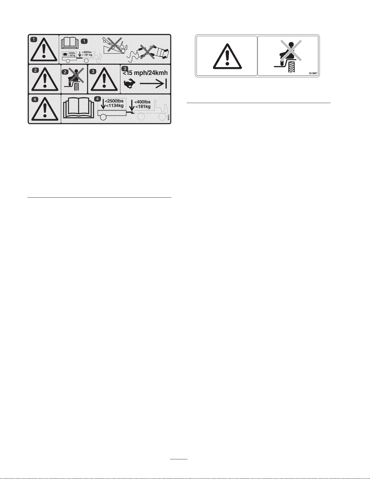
The safety alert symbol means
CAUTION, WARNING or DAN
GER personal safety
instruction". Read and under
stand the instruction because
it has to do with safety. Failure to comply with
the instruction may result in personal injury.
BEFORE OPERATING
1. Read and understand the contents of this
Operator's Manual before operating the machine.
Become familiar with all controls and know how to stop
quickly. A free replacement manual is available by
sending complete Model and Serial Number to:
The Toro Company
8111 Lyndale Avenue South
Bloomington, Minnesota 55420-1196
2. Never allow children to operate the machine. Do
not allow adults to operate the machine without proper
instructions. Only trained and authorized persons
should operate this vehicle. Anyone who operates the
vehicle should have a motor vehicle license.
3. Never operate the machine when under the
influence of drugs or alcohol.
4. Keep all shields and safety devices in place. If a
shield, safety device or decal is illegible or damaged,
repair or replace it before operation is commenced.
5. Tighten any loose nuts, bolts and screws to assure
machine is in safe operating condition. Make sure
Topdresser tongue mounting pins, hitch pins and
tongue jack are in place and secure.
6. Do not modify this equipment in any manner.
7. Do not operate machine while wearing sandals,
tennis shoes, sneakers or shorts. Also, do not wear
loose fitting clothing which could get caught in moving
parts. Always wear long pants and substantial shoes.
Wearing safety glasses, safety shoes and a helmet is
advisable and required by some local ordinances and
insurance regulations.
WHILE OPERATING
8. Do not run the engine in a confined area without
adequate ventilation. Exhaust fumes are hazardous
and could possibly be deadly.
9. NEVER carry passengers on the Top Dresser and
keep everyone away from the areas of operation.
10. Keep hands and feet out of hopper when unit is
operating or engine is running on tow vehicle.
11. Operator and passenger should remain seated
whenever the tow vehicle is in motion.
12. Using the machine demands attention. Failure to
operate tow vehicle safely may result in an accident,
tipover of tow vehicle and serious injury or death. Drive
carefully. To prevent tipping or loss of control:
A. Use extreme caution, reduce speed and
maintain a safe distance around sand traps,
ditches, creeks, ramps, any unfamiliar areas or
other hazards.
B. Watch for holes or other hidden hazards.
C. Use caution when operating tow vehicle on a
steep slope. Normally travel straight up and down
slopes. Reduce speed when making sharp turns or
when turning on hillsides. Avoid turning on hillsides
whenever possible.
D. Use extra caution when operating tow vehicle on
wet surfaces, at higher speeds or with a full load.
Stopping time will increase with a full load. Shift into
a lower gear before starting up or down a hill
E. Avoid sudden stops and starts. Do not go from
reverse to forward or forward to reverse without
coming to a complete stop.
F. Do not attempt sharp turns or abrupt maneuvers
or other unsafe driving actions that may cause a
loss of control.
G. Before backing up, look to the rear and assure
no one is behind. Back up slowly.
H. Watch out for traffic when near or crossing
roads. Always yield the right of way to pedestrians
and other vehicles. This machine is not designed
for use on streets or highways. Always signal
your turns or stop early enough so other persons
know what you plan to do. Obey all traffic rules and
check for local regulations on the operation of the
topdresser on or near highways.
I. Always watch out for and avoid low over-hangs
such as tree limbs, door jambs, over-head
walkways, etc. Make sure there is enough room
over head to easily clear the tow vehicle and your
head.
J. If ever unsure about safe operation, STOP
WORK and ask your supervisor.
13. When loading with sand, distribute load evenly.
Operate tow vehicle with extra caution when the hopper
is full of sand. Keep load balanced to prevent it from
shifting.
MAINTENANCE
14. Before servicing or making adjustments to the
topdresser, stop engine of tow vehicle, set parking
brake and remove key from engine to prevent
accidental starting of the engine.
15. Perform only those maintenance instructions
described in this manual. If major repairs are ever
needed or assistance is desired, contact an Authorized
TORO Distributor.

4
SAFETY INSTRUCTIONS
16. Be sure machine is in safe operating condition by
keeping nuts, bolts and screws tight.
17. Make sure all hydraulic line connectors are tight,
and all hydraulic hoses and lines are in good condition
before applying pressure to the system.
18. Keep body and hands away from pin hole leaks in
hydraulic lines that eject high pressure hydraulic fluid.
Use cardboard or paper to find hydraulic leaks.
Hydraulic fluid escaping under pressure can penetrate
skin and cause injury. Fluid accidentally injected into
the skin must be surgically removed within a few hours
by a doctor familiar with this form of injury or gangrene
may result.
19. To ensure optimum performance and safety,
always purchase genuine TORO replacement parts
and accessories to keep the Toro all TORO. NEVER
USE WILL-FIT" REPLACEMENT PARTS AND
ACCESSORIES MADE BY OTHER MANUFACTURERS.
Look for the TORO logo to assure genuineness. Using
unapproved replacement parts and accessories could
void the warranty of The Toro Company.

5
SAFETY AND INSTRUCTION DECALS
The following decals are installed on the machine. If any become damaged or illegible, replace it. The decal part
number is listed below and in your parts catalog. Replacement can be ordered from your Authorized Toro Distributor.
105-4586
1. Entanglement hazard, belt—stay away from moving parts. Do
not remove the shields or guards; always keep the shields and
guards in place.
105-0698
1. Warning—read the
Operator’s Manual.
105-0707
105-0708
1. Warning—thrown objects
98-3114
1. Entanglement hazard—stay away from moving parts.
100-7679
1. Warning—read the
Operator’s Manual.
2. Do not disconnect a trailer with an unbalanced load; it may
swing up or down and injure you.
3. Do not disconnect the trailer without first putting down the jack.
99-0015
1. Entanglement hazard, conveyor and brush—stay a safe
distance from the conveyor and brush.
58-6520
1. Grease

6
SAFETY AND INSTRUCTION DECALS
99-0016
1. Warning—read the
Operator’s Manual
for information on
stopping the machine; the maximum braking load is 3500 lb.
(1587 kg) trailer weight and 400 lb (181 kg) tongue weight. Do
not drive the machine and trailer down hill or you may lose
control.
2. Warning—do not carry passengers.
3. Warning—do not exceed 15 mph (24 kmh).
4. Warning—maximum tongue weight is 400 lb. (181 kg);
maximum trailer weight is 2500 lb. (1134 kg).
93-9867
1. Warning—do not carry passengers.

7
SPECIFICATIONS
Dimensions:
Height: 42.5
Length (plus tongue): 60.5"
Overall Length: 101.5"
Width: 73"
Hopper Dimensions:
Height: 15.3"
Top Length: 37.5"
Width: 73"
Inside Clear Width: 69"
Hopper Capacity:
25 cubic feet or 2050 lbs.
Spreading Width:
60"
Top Dressing Speed:
Variable to desired application rate.
2 to 8 mph
Maximum Transport Speed:
15 mph - Not for highway use.
Conveyor Belt:
Continuous 60" wide traction grip PVC belt with
heavy duty monofilament carcass.
Metering Gate:
Spring release flexible edge gate variable from
closed to 3" opening for light to heavy applications.
Tires:
(4) 18 x 10.5-8, 4 ply ribbed. Inflate to 20-30 psi.
Drive:
Hydraulic with chain driven pumps. Conveyor
motor with chain reduction. Brush motor direct
drive. Electro hydraulic solenoid control to activate
top dresser motors. Mobil DTE 15 M hydraulic fluid
in a closed loop hydraulic system with charge
pump and 10 micron filter.
Shipping Weight:
1454 lbs.
Maximum Weight:
3500 lbs. (GVW)
Required Attachments:
Topdresser Hydraulic Brake Kit Part No. 99-0154
Workman Heavy Duty Drawbar Model No. 44212
or
Heavy Duty Hitch frame Model No. 44213
Recommended Accessories:
Tachometer Kit (Liquid Cooled Gas or Diesel
Workman) Part No. 87-9950
Tachometer Kit-CE (Liquid Cooled Gas or Diesel
Workman) Part No. 87-9970
Tachometer Kit (Air Cooled Gas Workman)
Part No. 87-9960
Hand Throttle Kit Model No. 07416
Optional Accessories:
Tongue Jack (CE) Part No. 98-5016
Mobil EAL 224 H Biodegradable hydraulic fluid
(5 gal. container) Part No. 100-7674
Oil Filter Part No. 83-3010
Extra Vehicle Harness Part No. 99-0198
Specifications and design subject to change without notice.

8
LOOSE PARTS
NOTE: Use this chart as a checklist to assure all parts have been received. Without these parts, total set-up cannot
be completed.
Tongue Assembly 1
Lynch Pin 4 Mount Tongue Assembly to Topdresser
Clevis Pin 2
Wire Harness (3 pc.) 1 Mount to Tongue Assembly & Tow Vehicle
Hitch Pin 1
Skid Plates 4
Carriage Bolt 8 Mount to Topdresser
Flat Washer 8
Lock Nut 8
Operator's Manual 2 Read Before Operating Machine
Parts Catalog 1
Registration Card 1 Fill out and return to Toro
CE Certificate of Compliance 1
Pre-Delivery Check Inspection 1 Fill out and return to Toro
DESCRIPTION USEQTY.

9
SPECIAL TOW VEHICLE INSTRUCTIONS
Special Instructions for Workman
(3000/4000) and other utility tow vehicles
(tractors):
1. The TopDresser 2500 can be towed by most utility
tractors equipped with flotation tires for operation over
golf greens. The tractor must have adequate brakes
and drawbar hitch capacity to handle a 3500 lbs. (1587
kg.) trailer. Refer to Tractor Operator's Manual for
towing instruction and precautions.
2. The Workman(3000/4000) vehicle, equipped with
the Heavy Duty Drawbar (Model 44212 or 44213)
makes a good tow vehicle (4WD version is best for hilly
or bermed approaches to greens).
NOTE: For improved traction and when towing
TopDresser 2500, 1000 lbs. of weight can be added to
vehicle bed.
IMPORTANT: Do Not attempt pulling the Topdresser
2500 when loaded with material, with the standard
Workman (3000/4000) hitch. It is only rated to 1500 lbs.
and may bend or damage the cross tube axle support or
rear spring shackles. Always use the H.D. Drawbar Kit
Model 44212 or H.D. Frame Drawbar Model 44213.
IMPORTANT: Do Not attempt towing a loaded
topdresser with a light utility vehicle or run-about. They
do not normally have adequate brakes, suspension, or
frame strength to handle the weight of the
TopDresser2500.
3. Trailer Brakes are highly recommended when
using the Top Dresser 2500 in hilly terrain. When fully
loaded the topdresser may weigh as much as 3500
lbs.(GVW). This weight is well over the recommended
towing and braking limit of most utility vehicles. A
special trailer brake kit is available for direct installation
with the Workman (3000/4000) vehicle. This kit could be
adapted to other vehicles with a 12 volt brake light
source.

10
SET-UP INSTRUCTIONS
INSTALL TONGUE (Fig. 1 & 2)
1. Install tongue into topdresser receiving tube and
secure each end with a clevis pin and (2) lynch pins
(Fig. 1).
Figure 1
1. Front of Tongue
2. Tongue hitch
1
2
Figure 2
1. Rear of Tongue
1
INSTALL TONGUE HITCH (Fig. 1)
1. Level the tongue hitch to the tow vehicle drawbar
and secure using appropriate holes.
MOUNT OPTIONAL TONGUE JACK (Fig. 3)
1. Slide tongue jack onto mounting tube on tongue.
2. Align holes in jack with tongue and secure with
clevis pin.
Figure 3
1. Tongue jack
1
3. For storage, jack can be removed or rotated
upward and pinned.
INSTALL WIRE HARNESS (Fig. 4)
1. Plug topdresser wire harness into connector on
topdresser solenoid valve.
2. Secure appropriate terminals of tow vehicle
harness to tow vehicle battery (+ or -).
IMPORTANT: Make sure harness is connected to
correct terminals on battery.
3. Unplug loop back connectors from each harness
and plug harness's together.
Note: To prevent dirt or corrosion to harness connector
pins, Installloop back connectors to connectors
whenever vehicle harness's are disconnected.
4. Route wire harness' along tongue and secure to
tongue with wire connectors.
5. Plug controller harness connector into topdresser
wire harness connector. Route to operator's position
and secure along frame rail.
Figure 4
1. Topdresser harness
2. Controller harness
3. Tow vehicle harness
1
100-7882
10
2
3
NOTE: Wire harness has removable connectors which
allow permanently installing portion on vehicle, and
leaving the other portion with topdresser plugged in to
the solenoid.
MOUNT SKIDS (Fig. 5)
1. Mount a skid to each mounting bracket with (2)
carriage bolts, flat washers and locknuts. Position skids
as shown in figure 5.
Figure 5
1. Skid (4)
1
1

11
BEFORE OPERATING
CHECK HYDRAULIC SYSTEM FLUID
The machine's reservoir is filled at the factory with
approximately 2.5 gallons (9.5 l) of high quality
hydraulic fluid. Check the level of hydraulic fluid
before the machine is first operated and daily
thereafter. Appropriate hydraulic oils are listed below.
The following list is not assumed to be all-inclusive.
Hydraulic fluids produced by other manufacturers may
be used if they can cross reference to find an equivalent
to the products listed. Toro will not assume
responsibility for damage caused by improper
substitutions, so use only products from reputable
manufacturers who will stand behind their
recommendation.
Manufacturer ISO VG 46 Multigrade
Mobil DTE 15M
Amoco Rykon Premium ISO 46
Chevron Rykon Premium ISO Oil 46
Conoco Hydroclear AW MV46
Exxon Univis N46
Pennzoil AWX MV46
Shell Tellus T 46
Texaco Rando HDZ 46
IMPORTANT: The ISO VG 46 Multigrade fluid has been
found to offer optimal performance in a wide range of
temperature conditions. For those who prefer them,
Universal Tractor Fluids such as Mobilfluid 424 (or
equivalent) offer acceptable performance with possibly
some loss of efficiency at high ambient temperatures.
Note: Many hydraulic fluids are almost colorless,
making it difficult to spot leaks. A red dye additive for
the hydraulic system oil is available in 2/3 oz (20 ml)
bottles. One bottle is sufficient for 4-6 gal (15-232 l) of
hydraulic oil. Order part no. 44-2500 from your
authorized Toro distributor. Not recommended for
biodegradable fluid (use food coloring).
Biodegradable Hydraulic Fluid - Mobil 224H
IMPORTANT: Mobil EAL 224H is the only
biodegradable oil tested and approved by Toro.
Contamination by mineral-based hydraulic fluids may
change the biodegradability and toxicity of this oil.
When changing from standard fluid to the
biodegradable type, be certain to follow the approved
flushing procedure published by Mobil. Contact your
local Toro Distributor for details. This oil is available in 5
gallon (19 l) containers from your Toro Distributor, order
part no. 100-7674.
NOTE: Mobil EAL224H and most other hydraulic oils
are almost colorless, making it difficult detect leaks. A
non-toxic dye additive, such as food coloring, can be
added to improve visibility. Do not use hydraulic oil dyes
as they may be toxic.
Mobil EAL 224H is available, in 5 gallon containers (Part
No. 100-7674) from your local Toro Distributor. If you
wish to use an alternate biodegradable and nontoxic
hydraulic fluid, first the hydraulic tank, filter, all lines,
hoses, motors and pumps must be completely drained
to insure that the new oil will fully circulate and coat all
components in the hydraulic system, and reduce the
chance of gelling or stratifying in certain portions of the
circuit. Make sure to replace filter.
NOTE: Be certain that you select an equivalent ISO
Viscosity Grade 32/46 hydraulic fluid.
Mixing of hydraulic fluids-Regular petroleum hydraulic
fluids, such as Mobil DTE 15 M (Refer to Table) can be
added to the system without affecting the performance
or life of the components. These mineral based
hydraulic fluids and their normal wear additives, even in
small quantities, destroys the biodegradability and
non-toxicity of the fluid, and the entire system must be
considered environmentally hazardous.
1. Position machine on a level surface.
2. Clean area around filler neck and cap of hydraulic
tank. Remove cap from filler neck.
Figure 6
1. Hydraulic Tank Cap
1
3. Check fluid level. Fluid level should be 1/2 way up
screen in filler neck.
4. If level is low, add appropriate fluid to raise level.
Disposal And Spillage
Depending on contamination and/or degradation
levels, small amounts of spilled or leaked Mobil
EAL224H will not adversely affect ground water or the
environment. For small spills on the ground the
uncontaminated product will be readily biodegraded by
naturally occurring soil organisms when exposed to air.
Nonetheless, spillage of Mobil EAL 224H should be
handled similarly to currently accepted methods for
conventional mineral oil spills.

12
BEFORE OPERATING
Mobil EAL224H does not contain hazardous
substances reportable under CERCLA. Since all oil
spills are reportable, even a spill of this vegetable
oil-based product must be reported to the National
Response Center (the U.S. Coast Guard). Local
environmental agencies should also be consulted to
clarify local requirements.
Acceptable methods of disposal include use as a fuel
supplement, recycling and reclamation (that is, the
same disposal practices available for conventional
mineral oils). Since Mobil EAL 224H typically will not be
hazardous waste, additional disposal options may be
available, including land farming or processing through
sewage treatment facilities, if necessary approvals are
obtained from appropriate authorities.
The flushing solution may not be biodegradable,
therefore, it should be disposed of in an
environmentally safe manner. Follow procedures used
for disposing of conventional mineral oils.
Health And Safety
Based on available toxicological information, Mobil
EAL224H produces no significant adverse effects on
health when properly handles and used. No special
precautions are suggested beyond attention to good
personal hygiene, including laundering oil soaked
clothing and washing skin contact areas with soap and
water. For additional technical information or to order a
Material Safety Data Bulletin, call 1-800-662-4525 or
www.mobil.com.
CHECK TIRE PRESSURE
The tires are over-inflated for shipping. Therefore,
release some of the air to reduce the pressure. Correct
air pressure is 20-30 psi.
IMPORTANT: Maintain even pressure in all tires to
assure even weight distribution on turf and proper
machine performance. DO NOT UNDER INFLATE.
CHECK WHEEL BOLT TORQUE
WARNING
Torque wheel bolts to 8090 ft-lb after 14
hours of operation and again after 10 hours of
operation and every 200 hours thereafter. Fail
ure to maintain proper torque could result in
failure or loss of wheel.

13
CONTROLS
GATE METERING CONTROL
The knob and handle on left rear side of machine are
used to adjust and lock the gate into the desired open
height position.
1. Loosen the adjusting handle enough to allow knob
to slide freely in slot.
2. Set the gate into the desired position and tighten
the handle to lock into position.
RATE SCALE
Use rate scale to determine desired flow rate. Refer to
Sand Application Rate, page 16.
HAND CONTROL SWITCH
Activating hand control switch starts and stops the flow
of material from topdresser.
Figure 7
1. Gate adjusting knob & pointer
2. Locking handle
3. Rate scale
1
2
3

14
OPERATING INSTRUCTIONS
GENERAL
1. The Top Dresser 2500 is ground driven, so it will
need to be towed in order to check out operation of belt
and brush. Factory checks are performed on a powered
roller drum.
2. Top dressing works best at 2 to 8 miles per hour
(mph). The TopDresser 2500 compensates for
variations in travel speed, and will give consistent
distribution, even if travel speed changes during a pass
across the green. The operator/superintendent should
make a gate setting selection (variable in 1/8
increments to 13) and make a first pass to determine if
application rate is acceptable. (see Sand Application
Rate, page 16)
3. Operation begins when the hand control switch is
activated. This may require some practice to start and
stop the flow of material at the desired collar area of the
green or tee box.
4. Before loading hopper, make sure topdresser is
properly connected to tow vehicle, to prevent flip-up or
any unintended tongue movement. Do Not unhook
topdresser from tow vehicle with material in hopper.
Tongue may flip up causing injury.
5. When traveling through narrow areas such as
gates, door entries, etc. be aware that topdresser is
wider than the tow vehicle. Always check width before
proceeding and allow room for clearance to turn.
6. The top dresser adds extra towing weight to the
vehicle. Drive the vehicle safely.
A. Do not drive on highway or public roads.
B. Always SLOW the tow vehicle when
approaching and while making a turn.
C. Always SLOW the tow vehicle when driving in
unfamiliar areas or over rough terrain.
D. Always SLOW the tow vehicle when changing
direction of travel or preparing to stop.
E. When turning or driving on slopes, always
SLOW the tow vehicle, then turn to prevent loss of
control and possible upset.
F. DO NOT make sudden or sharp turns. DO NOT
suddenly change direction of travel on an incline,
ramp, grade, slope or similar surface.
G. Always adjust the tow vehicle speed to allow for
existing ground conditions such as wet slick
surfaces, loose sand or gravel and/or low visibility
conditions such as dim or bright lighting, fog, mist
or rain.
H. Be especially careful when driving a heavily
loaded vehicle down an incline or slope. Drive the
vehicle UP and DOWN the face of the slopes,
inclines or grades whenever possible. DO NOT
DRIVE across the face if at all possible. There is a
risk of upsetting the vehicle, which can result in
serious injury or death.
WARNING
Tipping or rolling the tow vehicle on a hill will
cause serious injury.
If engine stalls or you lose headway on a hill,
never attempt to turn tow vehicle around.
Always back straight down a hill in reverse
gear.
NEVER back down in neutral or with the clutch
depressed, using only the brakes.
NEVER add sideboards or panels to the top of
the hopper to increase the load capacity. The
additional weight will cause tipping or rolling of
the tow vehicle and lead to serious injury.
NEVER drive across a steep hill, always drive
straight up or down. Avoid turning on a hill.
Don't "drop the clutch" or slam on the brakes.
Sudden speed change can initiate tipover.
7. In tight areas, where a straight line pass across a
green is not possible, the TopDresser2500 can be
backed onto the area without harm and begin
topdressing when pulling forward. See the hydraulics
section for more information on the special features of
the Top Dresser 2500.
8. Before backing up, look to the rear and assure no
one is behind. Back up slowly and watch the top
dresser movement closely.
9. Use extreme caution and slow speed when backing
up the top dresser and tow vehicle.
10. The maximum recommended towing speed is 15
mph (Loaded 8 mph). As with any trailer, always use
caution when turning or backing up. Be aware of
persons or objects near the topdresser path of travel.
11. Watch out for traffic when near or crossing roads.
Always yield the right of way to pedestrians and other
vehicles.
12. If the top dresser begins to vibrate abnormally, stop
immediately. Shut off the tow vehicle engine. Repair all
damage before commencing towing.
13. If cavitation noise is heard while transporting across
the golf course, slow down, return to maintenance, and
investigate the cause. Do not exceed the 15 mph tow
speed. This unit was not designed for travel on
highways. Damage will occur to the internal hydraulic
components.

15
OPERATING INSTRUCTIONS
14. Before servicing or making any adjustments to the
top dresser:
A. Stop the tow vehicle and set the parking brake.
B. Shut off the tow vehicle's engine and remove
key from ignition.
15. Keep all nuts, bolts and other fasteners tightened
securely. Replace any parts removed during servicing
or adjustments.
16. When loading the top dresser mix into the hopper,
be careful that the loader or skid steer bucket does not
strike and buckle the hopper sides. Although designed
to be wide enough to clear most buckets, it is not strong
enough to take a direct hit and may deform the sheet
metal.
17. Dispersion is always best with dry material, but wet
sand can be spread with the special traction grip belt on
the Top Dresser 2500. Some adjustment to the gate
setting may be required, but the material should flow
out and spread relatively smooth and consistent. If any
slippage of the belt appears to be occurring, check the
Maintenance section; Belt adjustment and clean-out
provisions.
18. Topdress mix can vary in grain size as well as
moisture. It can also contain impurities that may either
damage greensmowers or plant tissue. Always control
the source of topdress material, and use care when
handling and loading.
19. A sight window is provided on the right front hopper
panel to monitor remaining material while topdressing.
It is good practice to glance over your right shoulder
and check the hopper volume before beginning
application to assure that you don't run out in the middle
of a pass.
20. The special oscillating drive axles on the Top
Dresser 2500 were designed to continue powering the
hydraulics while traversing over undulations and
irregularities in the surface of the green or tee. Always
approach severe berms slowly to avoid sudden impact
of the axles with the turf, and to reduce the potential of
leaving tire marks on the approach to the green.
WARNING
Rotating parts can grab or pinch. Stay clear of
brush and conveyor belt while unit is running.
Safe operation begins before taking the top dresser out
for a day's work. Read and understand the operating
instructions in the Toro Workman or other tow vehicle
operator's manual before using the topdresser.
CAUTION
The interlock switches are for the operator's
protection, so do not bypass them. Check op
eration of the switches daily to assure interlock
system is operating on the Workman. If a
switch is malfunctioning replace it before oper
ating. Regardless whether switches are oper
ating properly or not, replace them every two
years to assure maximum safety. Do not rely
entirely on safety switches - use common
sense!
OPERATION
1. Sit on operator's seat and engage tow vehicle
parking brake.
2. Disengage PTO (if so equipped) and return hand
throttle lever to OFF position (if so equipped).
3. Move shift lever to NEUTRAL position and depress
clutch lever.
4. Insert key into ignition switch and rotate it clockwise
to start the engine. Release key when engine starts.
5. Practice starting, driving and stopping the tow
vehicle. Always read and understand the operator's
manual for the tow vehicle before using this unit.
6. Check for smooth operation of belt before adding
material in hopper.
7. Place sand or other topdressing material in the
hopper. The maximum volume of material that can be
put into the hopper is 25 cubic feet. Generally, sand
weighs 100 pounds per cubic foot and could overload
the unit if more than 2050 pounds are loaded into the
hopper.
IMPORTANT: Overloading can result in side wall
deflection of tires and marking of green on first few
passes. Check tire pressures - Recommended
pressure is 20 - 30 p.s.i. max.
8. Transport to the area to be topdressed.
9. Adjust the metering gate to the desired rate. Lock
into position with the black knob.
10. For best results, move the shift lever into "LO" range
position. Select the desired forward speed and begin
moving. Refer to the following section, Sand
Application Rate.

16
OPERATING INSTRUCTIONS
DANGER
As a general rule, position the weight of the
load evenly from front to rear and evenly from
side to side.
Transporting or topdressing with a full load can
cause shifting of the sand. This shifting hap
pens most often while turning, going up or
down hills, suddenly changing speeds or while
driving over rough surfaces. Shifting loads can
lead to tipovers. Use caution when transport
ing or topdressing with a full load.
Heavy loads increase stopping distance and
reduce your ability to turn quickly without tip
ping over.
SAND APPLICATION RATE
The rate of sand applied depends on the gate setting.
Sand varies in moisture and coarseness (size of grain)
which effects the rate. These factors must be taken into
consideration when deciding the amount of sand
required for the application. Test a small area to decide
the correct amount. To increase application rate open
gate to a higher scale mark.
The TopDresser 2500 is ground driven which assures
consistent application, from green to green, when
towing speed is within the recommended 2-8 mph..
SAND PRECAUTIONS
The Topdresser 2500 is equipped with a flexible gate
edge (Fig. 8) and spring release mechanism to reduce
the chance of sand chunks or rocks getting lodged
during operation. To insure long belt life, sift or check
sand for rocks with sharp edges that may damage
conveyor belt.
Figure 8
1
1. Gate edge
COLD WEATHER OPERATION
Although limited by traction of drive tires, the
Topdresser 2500 may be used in cold weather, with
certain limitations, to apply a salt/sand mixture on
pavement for ice control. The PVC conveyor belt
material becomes very stiff in cold weather and requires
more power to operate belt. The life of the belt is
reduced by approximately 50% when operated below
temperatures of 40F (5C). Under no conditions
should the topdresser be operated below
temperatures of 20F (-7C).
1. Increase belt tension by adjusting spring
compression to 4 inches (101 mm). Refer to Adjusting
Conveyor Belt, page 20.
2. Always run belt, before adding material, to
assure moisture has not frozen belt system.
Damage to belt or roller may occur if belt/drive roller
slip.
IMPORTANT: Always re-set belt tension to normal
4-7/16" (112 mm) spring compression adjustment
before operating topdresser under normal
temperature conditions.

17
LUBRICATION
GREASING BEARINGS
The Topdresser 2500 has 13 grease fittings that must be
lubricated with a No. 2 Lithium based grease. Lubricate
annually or after every 200 hours of operation.
The grease fitting locations and quantities are: Roller
shaft bearings (4) (Fig. 9), Brush shaft bearing (1)
(Fig. 9), Pivot bearings (4) (Fig. 10) and Wheel bearings
(4) (Fig. 10).
IMPORTANT: Lubricate the bearings to maintain a
slight leakage between bearings and housings. Too
much grease can cause overheating aor damage to
seals.
NOTE: We do not recommend lubricating the drive
chains unless they become stiff because of rust. If the
chain rusts, it may be lubricated lightly with a
DRY-TYPE LUBRICANT. This will reduce the chance
for build-up of sand or other topdress material on
chain.
Figure 9
(2)
(2)
Figure 10
(4)
(4)

18
MAINTENANCE
JACKING TOPDRESSER
1. The jacking points on the topdresser are the skids.
2. Any load material must be removed from hopper
before working under raised topdresser.
3. Do not work under topdresser without jack stands
supporting it.
4. Pivot wheels up or down to expose wheel bolts.
WARNING
If wheels are removed and re-installed, make
sure to torque wheel bolts to 8090 ft-lb . Fail
ure to maintain proper torque could result in
failure or loss of wheel.
Figure 11
1. Skid (4)
1
1
CHANGING HYDRAULIC FLUID
Change hydraulic fluid after annually or every 200
operating hours, in normal conditions. If fluid becomes
contaminated, contact your local TORO distributor
because the complete system must be drained.
Contaminated fluid looks milky or black when
compared to clean oil.
1. Position machine on a level surface.
2. Remove fitting from bottom of reservoir and let
hydraulic fluid flow into drain pan. Reinstall and tighten
fitting when hydraulic fluid stops draining.
Figure 12
1. Hydraulic Tank Cap
1
3. Fill reservoir with approximately 2.5 gallons (9.5 l) of
hydraulic fluid. Refer to Checking Hydraulic Fluid.
IMPORTANT: Use only hydraulic fluids specified.
Other fluids could cause system damage.
4. Check level of fluid and add enough to raise to
proper level. DO NOT OVER FILL. Refer to Checking
Hydraulic Fluid.
5. Install reservoir cap.
REPLACING HYDRAULIC FILTER
Change hydraulic filter annually or after every 200
operating hours, in normal conditions.
Use the Toro replacement filter (Part No. 86-3010.
IMPORTANT: Use of any other filter may void the
warranty on some components.
1. Position machine on a level surface.
2. Clean area around filter mounting area. Place drain
pan under filter and remove filter.
Figure 13
1. Hydraulic Filter
1
3. Lubricate new filter gasket.
4. Assure filter mounting area is clean. Screw filter on
until gasket contacts mounting plate. Then tighten filter
one-half turn.
5. Check for leaks by towing machine to power the
hydraulic system.
CHECKING HYDRAULIC LINES AND
HOSES
Inspect hydraulic lines and hoses daily for leaks, kinked
lines, loose mounting supports, wear, loose fittings,
weather deterioration and chemical deterioration.
Make all necessary repairs before operating.

19
MAINTENANCE
WARNING
Keep body and hands away from pin hole leaks
or nozzles that eject high pressure hydraulic
fluid. Use cardboard or paper to find hydraulic
leaks. Hydraulic fluid escaping under pressure
can penetrate skin and cause injury. Fluid acci
dentally injected into the skin must be surgical
ly removed within a few hours by a doctor famil
iar with this form of injury or gangrene may re
sult.
BRUSH ADJUSTMENT
Brush must make enough contact with conveyor belt to
disperse topdressing material but not restrict the
rotation of the brush. A piece of stiff paper can be
inserted between the conveyor belt and the brush to
check the adjustment. The brush must be the same
height from side to side. The brush adjustment should
be checked weekly for wear. The bristles of the brush
will wear under normal conditions and the distance
from the brush to conveyor belt should be maintained to
prevent uneven wear of the brush.
NOTE: If using moist top dressing materials, brush may
have to be adjusted so bristles will whisk material from
between conveyor belt lugs without severely contacting
smooth portion of belt.
1. Loosen nuts securing bearing housing (Fig. 14) to
right side of machine.
Figure 14
1. Bearing housing
1
2. Loosen nuts securing brush motor (Fig. 15) to left
side of machine.
Figure 15
1. Brush motor
1
3. Slide brush into position on right side. Finger
tighten nuts.
4. Slide brush into position on left side. Finger tighten
nuts.
5. Insert a piece of stiff paper between the brush and
the conveyor belt. The brush must be the same height
from side to side.
6. If the adjustment is correct, tighten nuts. If not,
repeat procedure.
TENSIONING DRIVE CHAINS
The chains should be tensioned so they deflect 1/8". Do
not over tighten, this will cause chain wear. Do not
operate with a loose chain, this will cause sprocket
wear.
Conveyor Belt Chain
1. Remove chain cover (Fig. 16).
Figure 16
1. Chain cover
1
2. Loosen bolts and nuts securing motor and sprocket
assembly to the main frame (Fig, 17).
3. Rotate motor and sprocket assembly, in mounting
slots, until proper tension is achieved.

20
MAINTENANCE
Figure 17
1. Drive chain
2. Motor & sprocket assembly
1
2
4. Tighten mounting bolts.
5. Install chain cover.
Wheel Drive Chain
1. Loosen carriage bolts and nuts securing hydraulic
motor/pump to axle cradle (Fig. 18).
Figure 18
1. Hydraulic motor
2. Axle cradle cut-out
1
12
2. Rotate motor sprocket assembly until proper chain
tension is attained.
NOTE: Access to chain is thru cut out in lower side of
axle cradle.
3. Tighten mounting bolts.
NOTE: We do not recommend lubricating the drive
chains unless they become stiff because of rust. If the
chain rusts, it may be lubricated lightly with a
DRY-TYPE LUBRICANT. This will reduce the chance
for build-up of sand or other topdress material on
chain.
ADJUSTING CONVEYOR BELT
When conveyor belt is adjusted properly, the
compressed length of each compression spring
should be 4-7/16" (112 mm). Adjust conveyor belt
as follows:
1. Loosen jam nuts and adjust tension rod nuts to
attain desired tension.
Figure 19
1. Tension rod
2. Compression spring
3. Jam nut
4. Nut
1
3
4 2
4-7/16"
2. Tighten jam nuts to lock adjustment.
3. Check to insure that the center distance between
conveyor belt roller shafts (Fig. 20), on each side of
machine, are equal distance (approximately 35-1/4").
Figure 20
1. Conveyor belt roller
shafts
1
1
35-1/4"
REPLACING CONVEYOR BELT
When replacing a damaged or worn conveyor belt,
always inspect hopper seals (Fig. 21) and gate edge
(Fig. 21) for wear or torn edges. Replace worn or torn
components to insure proper operation of new
conveyor belt.
Figure 21
1. Hopper seal
2. Gate edge
1
1
2
1. Remove chain cover (Fig. 22).
This manual suits for next models
1
Other Toro Lawn Mower manuals

Toro
Toro 22197 User manual

Toro
Toro TimeCutter Z5030 User manual

Toro
Toro Sand Pro 2040Z User manual

Toro
Toro Greensmaster 3000 Series User manual

Toro
Toro Groundsmaster 4000 User manual

Toro
Toro TimeCutter HD X4850 User manual

Toro
Toro 30934 User manual

Toro
Toro 20955 User manual

Toro
Toro 30473 User manual

Toro
Toro ProLine 30165 User manual