Toro Later VP Raveon User manual

AOld Radio Removal
Later VP Raveon Radio Kit
Installation Instructions
Disconnect power
from radio interface board.
Disconnect
power passthru.
Disconnect ground.
Disconnect wireline
connection from modem.
Disconnect
antenna cable.
From opposite side,
remove mounting nuts.
Remove radio assembly.
Disconnect modem from
timing mechanism.
1
6 7 8
2
53
RISK OF ELECTRIC SHOCK.
Before replacing the radio, be sure to disconnect power to the pedestal.
4

BNew Radio Installation
standard modem
connection
The New Radio Kit
power connection
jumpers
From opposite side,
secure with nuts.
Connect to timing mechanism.
Connect antenna cable.
Insert radio assembly.
(optional) Connect
standard modem.
Connect power
passthru too.
TM connection
1
4
8
7
2
5
3
6
For VP controller,
all four jumpers should be
to the left.
Connect power to
radio interface board.
antenna connection
An optional standard modem
is only required if any wireline
satellites are connected to the
radio satellite.
For Systems with Maxon Radios
e VP satellite with Raveon radio requires a Field Interface Unit (FIU) with
a Raveon radio (P/N FIU-2011DR) to communicate. If your current system,
along with the FIUs, employs the (older) Maxon radios, the Raveon radio
must be put into “bell202” mode for successful communication.
Required Items:
• Radio Manager software from Raveon
• USB to Serial (DB9) cable with included drivers
• 12V Phoenix power connector (from authorized Toro distributor)
• 12V power supply for radio (from authorized Toro distributor)
To put the Raveon radio into bell202 mode:
1. Disconnect all power to the controller. Remove the radio. Place it next to
the Lynx computer on a static-free surface.
2. At the computer running Lynx, install the drivers for the USB
to Serial (DB9) cable. Reboot computer.
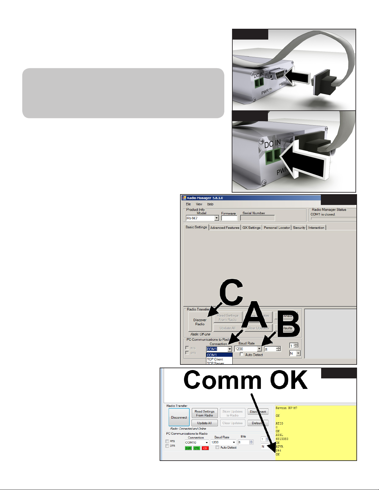
3. Plug USB cable into a USB port and Serial port on radio (Figure 1).
4. Connect Phoenix power cable into 12V power supply.
Plug other end into DC IN port on radio (Figure 2).
5. Plug in 12V power supply.
6. Launch Radio Manager. See Figure 3.
7. Select appropriate COM port (Figure 3, A).
8. Change the baud rate to 1200 (Figure 3, B)
9. Press ‘Discover Radio’ button (Figure 3, C).
e radio should be discoverd (Figure 4).
10. At the command line, issue the following commands
to the Raveon radio:
ATMT 4
ATR2 15
ATBP 1
ATIO 7
TXTOT 60
11. To exit a Raveon radio from bell202 mode
(to recommunicate with other Raveon radios,
for example), issue the following commands:
ATMT 0
ATR2 3
ATBP 0
ATIO 0
12. All interface board jumpers (both the satellite
and FIU) must be set to the left, to the ‘VP’
side (see frame 1 on previous page).
Figure 1
Figure 4
Figure 3
Figure 2

Changing the Frequency of the Radio
At the time of installation, your authorized Toro installer should congure the radio to work properly.
In the future, if it becomes necessary to change the radio frequency, follow the steps below.
See Required Items, previous page.
Steps
1. Follow steps 1-9 on the previous page.
2. To see current radio frequency, enter ATFX into the command
line (Figure 5).
3. To change the frequency, simply add an appropriate frequency
number to that command. Example: ATFX 460.5
UHF frequency range is from 450 to 470 MHz. Frequency
number specied must be between those numbers.
4. Software will conrm the change (Figure 6). It is possible to
manually conrm the change by simply typing in ATFX again.
5. Power down power supply and disconnect power line and serial
cable.
6. Install radio back into controller.
An FCC license is required to operate on any given UHF
frequency. Frequency coordination (selection) is handled
through the Personal Communications Industry Association
(PCIA) (800-759-0300) and an application must be
submitted to the FCC. ere is a PCIA fee and FCC license
fee that must be paid as well.
Figure 5
right here
Figure 6
conrmed
4
© 2016 The Toro Company • Irrigation Division • 1-877-345-8676 Form Number 373-0885 Rev. A
e Toro Company and its aliate, Toro Warranty Company, pursuant
to an agreement between them, jointly warrants to the owner each new
piece of irrigation equipment (featured in the current catalog at date of
installation) against defects in material and workmanship for a period
described below, provided they are used for irrigation purposes under
manufacturer’s recommended specications.
During the warranty period, we will repair or replace, at our option, any
part found to be defective. Your remedy is limited solely to the replace-
ment or repair of defective parts.
is warranty does not apply (i) to Acts of God (e.g., lightning, ooding,
etc.); or (ii) to products not manufactured by Toro when used in
conjunction with Toro products, or (iii) where equipment is used, or
installation is performed in any manner contrary to Toro’s specications
and instructions, nor where equipment is altered or modied.
Return the defective part to your irrigation contractor or installer, or
your local Golf Irrigation Distributor, or contact e Toro Company,
5825 Jasmine St., Riverside, California, 92504, (800) 664-4740, for the
location of your nearest Toro distributor, or outside the United States,
call (951) 688-9221.
Neither Toro nor Toro Warranty Company is liable for indirect,
incidental or consequential damages in connection with the use of
equipment, including but not limited to vegetation loss, the cost of
substitute equipment or services required during periods of malfunction,
or resulting non-use, property damage or personal injury resulting from
installer’s actions, whether negligent or otherwise. Some states do not
allow the exclusion of incidental or consequential damages, so the above
exclusion may not apply to you.
All implied warranties, including those of merchantability and tness for
use, are limited to the duration of this express warranty.
Some states do not allow limitations on how long an implied warranty
lasts, so the above limitation may not apply to you. is warranty gives
you specic legal rights and you may have other rights which vary from
state-to-state.
All Toro golf control systems (central controls, eld satellite controllers,
GDC, CDS and Turf Guard), unless covered by a Toro NSN Support
Plan, are covered by this warranty for one year from date of installation.
FCC Part 22 and Part 90 of the FCC Rules
Domestic: is equipment has been tested and found to comply with
the limits for a FCC Class A digital device, pursuant to part 15 of the
FCC Rules. ese limits are designed to provide reasonable protection
against harmful interference when the equipment is operated in a
commercial environment. e equipment generates, uses, and can radiate
radio frequency energy and, if not installed and used in accordance
with the instruction manual, may cause harmful interference to the
radio communications. Operation in a residential area is likely to cause
harmful interference in which case the user will be required to correct the
interference at his own expense.
International: is is a CISPR 22 Class A product. In a domestic
environment, this product may cause radio interference, in which case
the user may be required to take adequate measures.Each stations can
activate up to two solenoids.
is product, utilizing a Class 2 transformer tested to UL1585, satises
the requirements of a Class 2 Power Source as dened in the NFPA 70
(NEC), Article 725.121(A)(3).
Warranty and FCC Notice
Other Toro Radio manuals


