Toro 51487 User manual

FormNo.3377-756RevA
12inCordlessTrimmer
ModelNo.51487—SerialNo.313000001andUp
ModelNo.51487T—SerialNo.313000001andUp
Operator'sManual
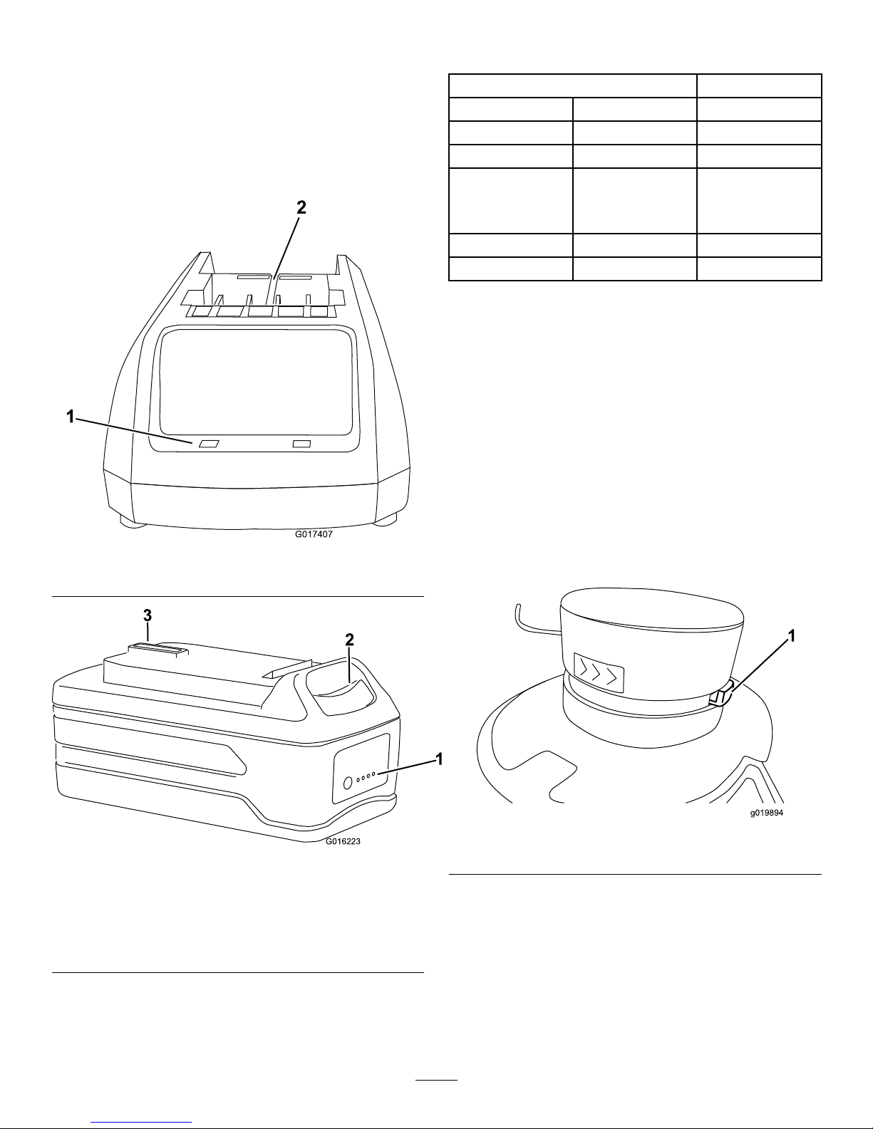
Model51487Tdoesnotincludeabatteryoracharger.
Ifyouhavequestionsorproblems,contactusatwww.Toro.comor
calltollfree1-800-237-2654(US)or1-800-248-3258(Canada)before
returningthisproduct.
GeneralSafetyRules
WARNING
CALIFORNIA
Proposition65Warning
Batteryposts,terminals,andrelated
accessoriescontainleadandleadcompounds,
chemicalsknowntotheStateofCalifornia
tocausecancerandreproductiveharm.
Washhandsafterhandling.
WARNING:Whenusingelectricgardeningappliances,basic
safetyprecautionsshouldalwaysbefollowedtoreducetheriskof
re,electricshock,andpersonalinjury,includingthefollowing:
Readallinstructions.
Theterm“powertool”inallofthewarningsreferstoyour
mains-operated(corded)powertoolorbattery-operated(cordless)
powertool.
1.Workareasafety
A.Keepworkareacleanandwelllit.Clutteredordark
areasinviteaccidents
B.Donotoperatepowertoolsinexplosive
atmospheres,suchasinthepresenceofammable
liquids,gasesordust.Powertoolscreatesparks
whichmayignitethedustorfumes.
C.Keepchildrenandbystandersawaywhileoperating
apowertool.Distractionscancauseyoutolose
control.
2.Electricalsafety
A.Powertoolplugsmustmatchtheoutlet.Never
modifythepluginanyway.Donotuseany
adapterplugswithearthed(grounded)powertools.
Unmodiedplugsandmatchingoutletswillreducerisk
ofelectricshock.
B.Avoidbodycontactwithearthedorgrounded
surfaces.Thereisanincreasedriskofelectricshockif
yourbodyisearthedorgrounded.
C.Donotabusethecord.Neverusethecordfor
carrying,pullingorunpluggingthepowertool.
Keepcordawayfromheat,oil,sharpedgesor
movingparts.Damagedorentangledcordsincrease
theriskofelectricshock.
D.Donotexposepowertoolstorainorwetconditions.
Waterenteringapowertoolwillincreasetheriskof
electricshock.
E.Ifoperatingapowertoolinadamplocationis
unavoidable,useasupplyprotectedbyaresidual
currentdevice(RCD)inAUSoragroundfault
interrupt(GFI)intheUSA.UseofanRCDorGFI
reducestheriskofelectricshock.
3.Personalsafety
A.Stayalert,watchwhatyouaredoinganduse
commonsensewhenoperatingapowertool.Do
notuseapowertoolwhileyouaretiredorunderthe
inuenceofdrugs,alcoholormedication.Amoment
ofinattentionwhileoperatingpowertoolsmayresult
inseriouspersonalinjury.
B.Usepersonalprotectiveequipment.Alwayswear
eyeprotection.Protectiveequipmentsuchasdust
mask,non-skidsafetyshoes,hardhat,orhearing
protectionusedforappropriateconditionswillreduce
personalinjuries.
C.Preventunintentionalstarting.Ensuretheswitch
isintheoff-positionbeforeconnectingtopower
sourceand/orbatterypack,pickinguporcarrying
thetool.Carryingpowertoolswithyourngeronthe
switchorenergizingpowertoolsthathavetheswitch
oninvitesaccidents.
D.Removeanyadjustingkeyorwrenchbeforeturning
thepowertoolon.Awrenchorakeyleftattachedto
arotatingpartofthepowertoolmayresultinpersonal
injury.
E.Donotoverreach.Keepproperfootingandbalance
atalltimes.Thisenablesbettercontrolofthepower
toolinunexpectedsituations.
F.Dressproperly.Donotwearlooseclothingor
jewelry.Keepyourhair,clothingandglovesaway
©2013—TheToro®Company
8111LyndaleAvenueSouth
Bloomington,MN55420
Registeratwww.Toro.com.OriginalInstructions(EN)
PrintedinChina.
AllRightsReserved*3377-756*A

frommovingparts.Looseclothes,jewelry,orlonghair
canbecaughtinmovingparts.
G.Keephandsandfeetawayfromthecuttingarea.
4.Powertooluseandcare
A.Donotforcethepowertool.Usethecorrectpower
toolforyourapplication.Thecorrectpowertoolwill
dothejobbetterandsaferattherateforwhichitwas
designed.
B.Donotusethepowertooliftheswitchdoesnotturn
itonandoff.Anypowertoolthatcannotbecontrolled
withtheswitchisdangerousandmustberepaired.
C.Disconnecttheplugfromthepowersourceand/or
thebatterypackfromthepowertoolbeforemaking
anyadjustments,changingaccessories,orstoring
powertools.Suchpreventivesafetymeasuresreduce
theriskofstartingthepowertoolaccidentally.
D.Storeidlepowertoolsoutofthereachofchildren
anddonotallowpersonsunfamiliarwiththepower
toolortheseinstructionstooperatethepowertool.
Powertoolsaredangerousinthehandsofuntrained
users.
E.Storeidleappliancesindoors.Whennotinuse,
appliancesshouldbestoredindoorsinadryandhigh
orlocked-upplace,outofthereachofchildren.
F.Maintainpowertools.Checkformisalignmentor
bindingofmovingparts,breakageofpartsand
anyotherconditionthatmayaffectthepowertools
operation.Ifdamaged,havethepowertoolrepaired
beforeuse.Manyaccidentsarecausedbypoorly
maintainedpowertools.
G.Usethepowertoolinaccordancewiththese
instructionsandinthemannerintendedforthe
particulartypeofpowertool,takingintoaccountthe
workingconditionsandtheworktobeperformed.
Useofthepowertoolforoperationsdifferentfromthose
intendedcouldresultinahazardoussituation.
H.Keepguardsinplaceandinworkingorder.
5.Service
Haveyourpowertoolservicedbyaqualiedrepair
personusingonlyidenticalreplacementparts.Thiswill
ensurethatthesafetyofthepowertoolismaintained.
6.BatterySafety
A.Donotchargeapplianceinrain,orinwetlocations.
B.Donotusebattery-operatedapplianceintherain.
C.Useonlythefollowingtypeandsizebattery:Toro
batterymodel88504or88506andbatterycharger
88503.
D.Removeordisconnectthebatterybeforeservicing,
cleaning,orremovingmaterialfromthegardening
appliance.
E.Donotdisposeofthebatteryinare.Thecellmay
explode.Checkwithlocalcodesforpossiblespecial
disposalinstructions.
F.Donotopenormutilatethebattery.Releasedelectrolyte
iscorrosiveandmaycausedamagetotheeyesorskin.
Itmaybetoxicifswallowed.
G.Exercisecareinhandlingbatteriesinordernottoshort
thebatterywithconductingmaterialssuchasrings,
bracelets,andkeys.Thebatteryorconductormay
overheatandcauseburns.
H.Chargingtimewillbeincreasedifthebatteryischarged
whenthetemperatureisnotbetween41to104degrees
F(5to40degreesC).
SAVETHESEINSTRUCTIONS
2

SafetyandInstructionalDecals
Safetydecalsandinstructionsareeasilyvisibletotheoperatorandarelocatednearanyareaofpotentialdanger.
Replaceanydecalthatisdamagedorlost.
SymbolNameDesignation/Explanation
DCDirectcurrentTypeofcurrent
VVoltsVoltage
121–7615
121–7614
125–3227
Model51487
1.Warning—readtheOperator’sManual;donotoperatein
wetconditions;weareyeprotection.
121–7658
Model51487T
1.Warning—readtheOperator’sManual;donotoperatein
wetconditions;weareyeprotection.
125–3291
3

121–7602
125–3226
121–7606
4

Setup
LooseParts
Usethechartbelowtoverifythatallpartshavebeenshipped.
ProcedureDescriptionQty.Use
Screw2
1Wall-mountingbracket1Mountthewall-mountingbracket.
2Nopartsrequired–
Auxiliaryhandle1
Latch1
3Brace1
Installtheauxiliaryhandle.
Guard1
4Phillipsheadscrew1
Mounttheguardtothebaseofthe
trimmer.
5Wireedgeguard1Installtheedgeguard
6Nopartsrequired–Adjustthetrimmerheightandbase
orientation
1
MountingtheWall-Mounting
Bracket
Partsneededforthisprocedure:
2Screw
1Wall-mountingbracket
Procedure
Note:Thebracketshouldbemountedindoorsandthetrimmer
shouldbeoutofthereachofchildren.
1.Placethebracketagainstthewallandmarkthe2hole
locations.
2.Drillthepilotholes.
A.Ifmountingthebracketonwallboard,plaster,or
cement,drill2holesforthewallanchors(notsupplied)
atthemarkedlocations.
B.Ifmountingthebracketonwood,drill2holesslightly
smallerthanthediameterofthescrewthreadsatthe
markedlocations.
3.Installthescrews(Figure1).
A.Ifmountingthebracketonwallboard,plaster,or
cement,insertthe2wallanchors(notsupplied)intothe
holesthenthreadthescrewsintothewallanchors.
B.Ifinstallingthebracketonwood,drivethe2screwsinto
thewall.
Figure1
1.Screw
5

2
AssemblingtheTrimmer
NoPartsRequired
Procedure
1.Removethetapeandthetubefromtheupperpole
(Figure2).
Figure2
1.Tube3.Lowerpole
2.Tape
2.Slidetheupperpoleintothelowerpole,liningupthetabin
theupperpolewiththereceivingtabsinthelowerpole,and
secureitbytighteningthescrew.
Note:Thereisanaudibleclickwhentheupperpoleand
lowerpoleareintheproperposition.
Figure3
1.Upperpole3.Shaftclamp
2.Screw
3.Cutthezip-tieandremoveitfromthetriggerhandle
(Figure4).
Figure4
1.Zip-tie
6

3
InstallingtheAuxiliaryHandle
Partsneededforthisprocedure:
1Auxiliaryhandle
1Latch
1Brace
Procedure
1.Positiontheauxiliaryhandleontheshaftofthetrimmerwith
thesmoothsurfacefacingtheoperator(Figure5).
G017277
Figure5
1.Auxiliaryhandle3.Brace
2.Latch
2.Slidethebraceintotheauxiliaryhandlesothatthebrace
restsinthegroovealongtheshaft(Figure5).
3.Slidethelatchfromtheleftthroughthehandleandbrace
asshownandtightenthelatchscrewwithaPhillipshead
screwdriver(Figure5).
4
InstallingtheGuard
Partsneededforthisprocedure:
1Guard
1Phillipsheadscrew
Procedure
1.RemovethePhillipsheadscrewtapedtotheguard
(Figure6).
2.SlidetheguardontothetrimmerbaseasshowninFigure6.
G017622
Figure6
1.Phillipsheadscrew2.Guard
3.SecuretheguardusingaPhillipsheadscrew.
7

5
InstallingtheEdgeGuard
Partsneededforthisprocedure:
1Wireedgeguard
Procedure
Inserttheendsofthewireedgeguardintotheholesinthetrimmer
housing,asshowninFigure7.
G017621
1
Figure7
1.Wireedgeguard
6
AdjustingtheHandleHeight
andBaseOrientation
NoPartsRequired
Procedure
•Toadjusttheauxiliaryhandleheight,releasetheauxiliary
handlelatch,slidetheauxiliaryhandleupordowntothe
desiredheight,thensecuretheauxiliaryhandleinplaceby
closingtheauxiliarylatch(Figure8).
Figure8
1.Auxiliaryhandle2.Auxiliaryhandlelatch
•Toadjusttheorientationofthebase,pressdownonthe
rotatorbuttonlocatedatthebaseoftheshaft,thenmovethe
basetofacethedesireddirection(Figure9).
1
G015683
Figure9
1.Rotatorbutton
8

Operation
Important:Thebatterypackisnotfullychargedwhenit
ispurchased.Beforeusingthetrimmerforthersttime,
placethebatterypackinthechargerandchargeuntilthe
LEDindicatorsturngreen.Makesuretoreadallsafety
precautions.Withregularuse,itwillneedshortercharging
time.Ifstoringforaprolongedperiodoftime,removethe
battery.Whenreadytouseagain,chargethebatterypack
untiltheLEDindicatorsturngreen.
StartingtheTrimmer
1.Alignthetongueofthebatterypackwiththecavityinthe
handlehousing(Figure10).
g017453
1
2
3
Figure10
1.Triggerhandle3.Latch
2.Tongue
2.Graspthetriggerhandle(Figure10).
3.Pushthebatterypackintothehandleuntilthelatchlocks
intoplace.
4.Tostartthetrimmer,slidethelockswitchbacktotheOn
position,thensqueezethetrigger(Figure11).
g017454
1
2
Figure11
1.Lockswitch2.Trigger
StoppingtheTrimmer
Tostopthetrimmer,releasethetrigger.
9

ChargingtheBatteryPack
Important:Forbestresults,yourbatterytoolshouldbe
chargedinalocationwherethetemperatureismorethan
41degreesF(5degreesC)butlessthan104degreesF(40
degreesC).Toreducetheriskofseriouspersonalinjury,
donotstoreoutsideorinvehicles.Chargingtimewillbe
increasedifnotchargedwithinthisrange.
1.Turnthebatteryupsidedownandlineupthebatteryterminal
withtheslotinthecharger(Figure12andFigure13).
G017407
1
2
Figure12
1.LEDindicators2.Insertbatteryhere
G016223
1
2
3
Figure13
1.LEDindicators(levelof
charge)
3.Batteryterminal
2.Releasebutton
2.Slidethebatteryintothechargeruntilitclicksintoplace.
3.Toremovethebattery,pressdownonthereleasebutton
andslidethebatterybackwardsoutofthecharger.
4.RefertothetablebelowtointerprettheLEDindicatorson
thebatterycharger.
LEDCOLOR
LeftRightIndicates:
RedRedBatteryischarging
RedGreenFullycharged
RedOrangeBatteryistoo
warm:Remove
forapproximately
30minutes
RedGreenNobatterypresent
Red(blinking)Red(blinking)Defectivebattery
AdvancingtheLine
Thetrimmerisequippedwithanauto-feedhead.Thelinewill
advance6mm(1/4inch)eachtimeyoustopandstartthe
trimmer.Whenthelinereachesthebladeinthedeector,itwill
becutoffatthatlength.
1.Withthetrimmerrunning,releasetheswitchtrigger.
2.Waittwoseconds,thenpresstheswitchtrigger.
3.Resumetrimming.
AdvancingtheLineManually
Disconnectthestringtrimmerfromthepowersupply,thenpush
theredbuttonatthebaseofthespoolretainerwhilepullingonthe
trimmerlinetomanuallyadvancetheline.
Figure14
1.Button
10

Trimming
G016254
Figure15
Edging
Tousethetrimmerasedger,presstherotatorbuttonandrotate
theheadasshowninFigure16.
1
2
G015660
Figure16
1.Rotatorbutton2.Edgerguide
UsingthePowerSaverFeature
Engagingthepowersaverfeaturewillextendtheruntimeofthe
batterybyshorteningthelengthofthetrimmerlineanddecreasing
theloadonthemotor.
Ifyouareexperiencingreducedbatteryruntime,itisrecommended
thatyouengagethepowersaverfeature.
Pushdownandrotatethepowersaverknob(Figure17)180
degrees(1/2turn)toshortenthelengthofthetrimmerline.This
reducesthepowerconsumptionofthetrimmerandextendsthe
runtimeofthebattery.
Toresumeoperationintheregularmode,pushdownandrotate
thepowersaverknob180degrees(1/2turn).
g017455
1
Figure17
1.Powersaverknob
OperatingTips
•Keepthetrimmertiltedtowardtheareabeingcut;thisisthe
bestcuttingarea.
•Tiltthetrimmersothatthetrimmerstringislowestonthe
rightside.
•Thestringtrimmercutsbestwhenpassingtheunitfromleftto
right.Thiswillalsoavoidthrowingdebrisattheoperator.
•Usethetipofthestringtodothecutting;donotforcestring
headintouncutgrass.
•Wireandpicketfencescauseextrastringwear,even
breakage.Stoneandbrickwalls,curbs,andwoodmaywear
stringrapidly.
•Avoidtreesandshrubs.Treebark,woodmoldings,siding,
andfencepostscaneasilybedamagedbythestrings.
11

Figure18
1.Directionofrotation3.Stringpath
2.Idealcuttingrange
Maintenance
Aftereachuseofthetrimmer,completethefollowing:
1.Removethebatteryfromthetrimmer.
2.Wipethetrimmercleanwithadampcloth.Donothosethe
trimmerdownorsubmergeitinwater.
CAUTION
Thelinecut-offbladeonthedeectorissharpand
cancutyou.Donotuseyourhandstocleanthe
deectorshieldandblade.
3.Wipeorscrapecleanthecuttingheadareaanytimethereis
anaccumulationofdebris.
4.Checkandtightenallfasteners.Ifanypartisdamagedor
lost,repairorreplaceit.
5.Brushdebrisawayfromairintakeventsonmotorhousing
topreventthemotorfromoverheating.
ReplacingtheSpool
Useonly.065inch(1.6mm)diametermonolamentstring.Use
originalmanufacturer’sreplacementstringforbestperformance
(Toropartnumber88532or88524).
Important:Useofalargerdiameterstringwillcausethe
motortooverheatandfail.
1.Removethebattery.
2.Pushinthetabsonthesideofthespoolretainer(Figure19).
1
2
3
4
G015663
Figure19
1.Spoolretainer3.Slots
2.Spool4.Tabs
3.Pullthespoolretaineruptoremoveitandremovethespool.
4.Toinstallthenewspool,makesurethestringiscapturedin
oneoftheretainingslotsonthenewspool.Makesurethe
endofthestringextendsapproximately6inches(152mm).
5.Installthenewspoolsothatthestringalignswiththeeyelet
inthestringhead.Threadthestringintotheeyelet.
6.Pullthestringextendingfromthestringheadsothestring
releasesfromtheslotinthespool.
7.Reinstallthespoolretainerbydepressingtabsintoslotsand
pushingdownuntilspoolretainerclicksintoplace.
ReplacingtheString
1.Removethebattery.
2.Removethespool.SeeReplacingtheSpool(Figure19).
1
2
G015662
Figure20
1.Slotinupperspoolange2.Hole
12

Note:Removeanyoldstringremainingonthespool.
3.Thespoolwillacceptupto15feet(4.5m)ofstring.Use
only.065inch(1.6mm)diametermonolamentstring.
Note:Donotuseanyothergaugeortypeofstring,asthis
coulddamagethetrimmer.
4.Insertthestringintotheanchorholeintheupperpartof
thespool(Figure20).Windthestringontothespoolinthe
directionshownbythearrowsonthespool.
5.Placethestringintheslotontheupperspoolange,leaving
about6inches(152mm)extendedbeyondtheslot.
Note:Donotoverll.Afterwindingthestring,thereshould
beatleast1/4inch(6mm)betweenthewoundstringand
theoutsideedgeofthespool.
6.Replacethespoolandthespoolretainer.Referto
ReplacingtheSpool(page12).
PreparingtheBatteryPackfor
Recycling
WARNING
Beforerecycling,coverthebatterypack'sterminals
withheavy-dutyadhesivetape.Donotattemptto
destroyordisassemblethebatterypackorremove
anyofitscomponents.Lithium-ionbatteriesmustbe
recycledordisposedofproperlyatthenearestbattery
recyclingfacility.
Service
Shouldthisitemneedservice,taketheproducttoyourAuthorized
ToroServiceDealer.YourT oroDealerisspeciallytrainedtorepair
ToroproductsandwillensurethatyourTorostays“All”T oro.
Storage
•Cleanallforeignmaterialfromtheproduct.
•Storeitinawell-ventilatedplacethatisinaccessibleto
children.
•Keepawayfromcorrosiveagentssuchasgardenchemicals
andde-icingsalts.
Troubleshooting
Usingthebatterywhenitishotcanreducetheoperatingtime.
Thebatterywillautomaticallystopworkingwhenitisoverheated
topreventdamagetoit.Removethebatteryfromthechargerand
allowittocoolbeforeplacingitbackintothetrimmer.
Usingthebatterywhenthereismoistureontheleadscancause
thetrimmertomalfunction.Allowthebatterytodryorwipeitdry
beforeplacingitbackintothetrimmer.
Usingthetrimmertocutthickgrassintemperaturesabove90
Fahrenheit(32Celsius)mayreducetheruntime.Engagethe
powersavingfeaturetohelpincreasetheoperatingtime.Referto
UsingthePowerSaverFeature(page11).
13

Notes:
14

Notes:
15

TheToroPromise-ElectricProducts
ATwo-YearFullWarrantyforResidentialUsefortheUnitedStatesandCanada
TheT oroCompanyanditsafliate,T oroWarrantyCompany,pursuanttoanagreementbetweenthem,jointlywarrantthisproductfortwoyearsagainst
defectsinmaterialorworkmanshipwhenusedfornormalresidentialpurposes.*
IfyouthinkyourT oroProductcontainsadefectinmaterialsorworkmanship,ifyouhavequestionsorproblems,andbeforereturningthisproductcall
tollfree:
Trimmers:Blowers:Snowthrowers:
1-800-237-2654(US)
1-800-248-3258(Canada)
1-888-367-6631(US)
1-888-430-1687(Canada)
1-800-574-3312(Mexico)
1-800-808-2963(US)
1-800-808-3072(Canada)
Toreceiveareplacementorrepair,atouroption,returnthecompleteunittotheseller.UnitedStatesandCanadacustomersmayreturntheirproduct,
withproofofpurchase,toanyAuthorizedServiceDealer.UnitedStatescustomersmayalsoreturntheirproduct,withproofofpurchase,postage
prepaid,totheToroServiceCenter,5500SEDelaware,Ankeny,IA50021.
Thiswarrantycoversproductdefectsonly.NeitherTheToroCompanynorToroWarrantyCompanyisliableforindirect,incidental,or
consequentialdamagesinconnectionwiththeuseoftheToroProductscoveredbythiswarranty,includinganycostorexpenseofproviding
substituteequipmentorserviceduringreasonableperiodsofmalfunctionornon-usependingcompletionofrepairsunderthiswarranty.
Somestatesdonotallowexclusionsofincidentalorconsequentialdamages,sotheaboveexclusionsmaynotapplytoyou.Thiswarranty
givesyouspeciclegalrights,andyoumayalsohaveotherrightswhichvaryfromstatetostate.
CountriesOtherthantheUnitedStatesandCanada
CustomerswhohavepurchasedT oroproductsexportedfromtheUnitedStatesorCanadashouldcontacttheirToroDistributor(Dealer)toobtain
guaranteepoliciesforyourcountry,province,orstate.IfforanyreasonyouaredissatisedwithyourDistributor’sserviceorhavedifcultyobtaining
guaranteeinformation,contacttheToroimporter.Ifallotherremediesfail,youmaycontactusatT oroWarrantyCompany.
AustralianConsumerLaw
AustraliancustomerswillnddetailsrelatingtotheAustralianConsumerLaweitherinsidetheboxoratyourlocalT oroDealer.
*Residentialusemeansuseoftheproductonthesamelotasyourhome.PartNumber374-0262Rev.D
374-0262RevD
Other manuals for 51487
1
This manual suits for next models
1
Table of contents
Other Toro Trimmer manuals

Toro
Toro 240500001 User manual

Toro
Toro 51136 User manual

Toro
Toro 88713 User manual

Toro
Toro 66110T User manual

Toro
Toro Power Plex 14in 40V MAX 51482 User manual

Toro
Toro Power Plex 51481 User manual

Toro
Toro 51484 User manual

Toro
Toro 51480 User manual

Toro
Toro 51231 User manual

Toro
Toro 51956 User manual

Toro
Toro 66210T User manual

Toro
Toro TC 1000 User manual

Toro
Toro Flex-Force Power System 51840 User manual

Toro
Toro 53008 User manual

Toro
Toro 66120T User manual

Toro
Toro 66210T User manual

Toro
Toro 51248 User manual

Toro
Toro 88716 User manual

Toro
Toro Flex-Force Power System 60V MAX User manual

Toro
Toro 51494 User manual