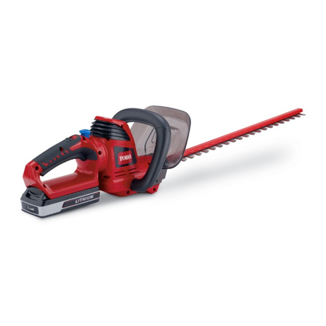
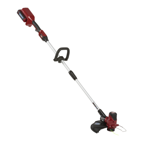
Toro 51550 User manual

OUTDOOR
APPLIANCE
DIVISION
Electric
Trimmer/
Weeder
--
.
I
SERVICE
MANUAL
..
CORDLESSTRIMMER/WEEDER
ModelNumber 51550
900
HOME DUTY TRIMMER/WEEDER
Model Numbers 51200
and 51225
1100 HEAVY DUTY TRIMMER/WEEDER
Model Numbers 51300
.
L
MARCH
1979

This servicerepairmanual
is
writtenfor use byAuthorizedToroApplianceServiceDealers.
Complete Trouble Shooting Guides, Wiring Diagrams and Service Instructionsare included.
The manual
is
divided intofive sections. The first section concerns
itself
with the automatic
line feedingdevicesused in the four different trimmers.Thesecondsectiondeals with the
900 and 1100 Trimmers, thethird withthe 1200 andthe fourth withthe Cordless. The fifth
section contains anillustrated
Parts
Catalogfor each model.
The Trouble Shooting Guides
at
the beginning of the first foursections follow
a
systematic
patternwhich will enable you tofind
a
problem quickly. Eachsection of theTrouble
Shooting Guide
is
numbered in the lower right hand corner.After finding the problem, you
need only refer to this same number in the service sectionfor complete repair instructions.
TABLE
OF
CONTENTS
AutomaticLine FeedAssembly
...........................................
1-4
TroubleShooting Guide
................................................
2
Service Instructions.
.................................................
3-4
900
&1100
Trimmers
..................................................
5-11
Trouble Shooting Guide
................................................
6
WiringDiagram
.......................................................
7
Service
I
Instructions
................................................
7
.
11
1200
Trimmer
.......................................................
13-19
TroubleShootingGuide
...............................................
14
WiringDiagram
......................................................
15
Service Instructions.
...............................................
15-19
Cordless Trimmer 21-30
TroubleShootingGuide
............................................
22-23
WiringDiagram
......................................................
24
Service Instructions.
...............................................
24-30
PartsCatalog
........................................................
31-47
900TrimmerModelNo.512008000001 9000100. 32-33
900 Trimmer Model No. 51 225
.
9000101
&
Up.
........................
34-35
1100Trimmer/Model No. 51300
.
8000001
.
9000100..
..................
36-37
1100Trimmer/Model No. 51325
.
9000101
&
Up.
.......................
38-39
..
1200Trimmer/Model No.51400
.
8000001
.
9000100..
..................
40-41
1200 Trimmer
/
Model No.51425
.
9000101
&
Up.
.......................
42-43
CordlessTrimmer/Model No. 51550
.
8000001
.
9115104
..........
.....
44-45
Cordless Trimmer/Model No. 51550
.
91 15105
&
Up
.....................
46-47
....................................................
. .
....................
No. 2 PhillipsScrewdriver
SmallStandardScrewdriver
Medium Standard Screwdriver
Large Standard Screwdriver
Long Nose Pliers
Diagonal CuttingPliers
Electrical Terminal CrimpingPliers
Scribe or Awl
TOOLREQUIREMENTS
No. 54 DrillBit (or objectsimilarinsize and hardness)
VOM Multimeter
ContinuityTester (oruse mulitimeter)
1/8" Pin Punch
SmallHammer
Vise
(or
similar support system)
Extension Cord
110Volt A.C. Power Source
COPYRIGHT
ALL
RIGHTS RESERVED
The
Toro
Company
-
1979
MINNEAPOLIS, MN
55420
-
U.S.A.
"US.
&
ForeignPatentsPending"
AUTOMATIC LINE FEED ASSEMBLY
900
HomeDuty
Trimmer/Weeder
Model Numbers51200 and
51
225
1100
Heavy
Duty
Trimmer/ Weeder
Model Numbers51300 and 51325
1200
Professional
Trimmer/Weeder
Model Numbers51400 and 51425
Cordless
Trimmer/
Weeder
Model Number 51550
1

TROUBLE
SHOOTING
GUIDE
t
I-
r
>
I-
'
-1
0
.I
0
--
-I
0
I---
lr'
I-
.g-
i
I-
2

AUTOMATICLINE
FEEDASSEMBLY
SERVICE
INSTRUCTIONS
CAUTION:THIS TOOL
IS
DOUBLE
INSULATED. TO MAINTAINITS ENGINEER-
I
ED SAFETYSTANDARDS USE ONLY
GENUINE TORO REPLACEMENT PARTS.
THESEAPPLIANCESFROM ALL POWER
SOURCESBEFORE ATTEMPTING ANY
REPAlRS.
1.1
REMOVESPOOLCAP (fig. 1.1)
Insertwidestpossiblebladescrewdriver
snugly into one of the two windowslots
on thespool hub and twist the screw-
driver 1/4 turn.
Figure1.1
1.11
REMOVING DIFFICULT SPOOLCAPS
.CORDLESSTRIMMERS (fig.
l.lla)
If
the spool
is
difficult to remove, pry or
break the spoolcap out with
a
screwdriver.
Figure 1.1
la
900,1100,
AND
1200
TRIMMERS
(fig.
1.11
b)
Holdthedrum steadyandunscrew the
spool incounter-clockwise direction.With
the spooland core removed, pry the spool
offthe core.
1.2
1.3
1.31
Figure 1.11
b
CHECKFORGRASS
OR
DIRT INSIDE
DRUM. CLEAN INSIDE DRUM.
With thespoolcapremoved, thoroughly
clean
out
the drum areaand visually in-
spect for any damage.
CHECK FOR LINE TIGHT ON SPOOL
The line must be wrapped firmly but free
to unwind easily during use. There should
be no loose line protruding from the
wrapped line.
REWINDSPOOL CORRECTLY(fig. 1.31)
Hook oneend of theline into
a
groove
onthe spool, allowingnomorethan 1/8
inch
of
line to protrude.Windline in
direction of arrows on spool.Wind in
level rows between spool flanges.
Figure1.31
1.4
CHECK
FOR
WORN
DRIVERTEETH (fig.l.4)
Remove the spoolcap tocheck the driver.
Inspect the driver teethtoinsurethatthey
are not severely roundedoffor completely
missing.
*-
Figure 1.4
3

SERVICE
INSTRUCTIONS
1.41REPLACE DRIVER
ALL UNITSEXCEPT 1978 CORDLESS
(fig. 1.41
a)
Remove thespool. Unscrew the core,
with driver, from the motor shaft. Gently
release the pressure the spring
is
applying
against the spool core. To install the new
driver, reverse procedures.
Figure 1.41
a
CORDLESS 8000001
&
UP
(fig.
1.41
b)
On the Cordless Trimmer(SerialNo.
8000001-9115104)
a
white driver was
pressed on
at
the factory. Pry off the
driver to remove
it.
Note: If thedriver
is
beige colored Cordless Trimmer(Serial
No.9115105
&
up),
it
is
threaded onto
the motor shaft. Replace the white driver
by firmly pushing
it
onthe motor shaft,
while rigidly supporting the oppositeend
of the motor shaft.Note that the motor
shaftand white driver both have
a
flat
side.
Figure 1.41b
1.5 CHECK FOR DIRTY OR DAMAGED
CORE
(fig.
1.5)
Figure 1.5
4
,-
Inspect the spool core after removing the
spool cap. Look for broken orworn teeth
thatwouldallowthe drivertoskip. A build-
up
of
dirt inside the core would stop the
driver from indexing.
1.51 CLEAN OR REPLACE CORE
Remove and replace core
as
driver replace-
ment insection 1.41.
1.61978 CORDLESS TRIMMER-CHECK FOR
DRUMRUBBING MOTOR
(fig.
1.6)
Theheadassemblywas "press-fit" on the

motor shaft up to the heatsink.
It
could
possibly be hitting against the base of the
motor.
.
Figure
1.6
1.61 REPLACE DRUMANDMOTOR WITH
NEW STYLE
(fig.
1.61)
Replace the
#88140
Motor Assembly
with
a
#88150 Motor Assemblyand
#88151 Automatic Line FeedAssembly.
To replacethesecomponents,pleasere-
fer tosection
2.6
and
2.7.
88140~18814188150w/88151
Figure
1.6
1

900
Home
Duty
Trimmer/ Weeder
Model Numbers51200and 51225
and
1100
Heavy
Duty
Trimmer/ Weeder
Model Numbers51300and 51325

TROUBLESHOOTINGGUIDE
I-

WIRING
DIAGRAM
IRING HARNESS
-
LOWER
WIRING HARNESS
-
UPPER CONNECTOR
CONNECTOR
SWfTCH -SINGLE SPEED
.
SERVICEINSTRUCTIONS
INSULATED. TO MAINTAIN ITS ENGINEER-
ED SAFETYSTANDARDS USE
ONLY
GENUINETOROREPLACEMENTPARTS.
I
THESEAPPLIANCESFROM ALL POWER
SOURCESBEFORE ATTEMPTING ANY
2.0 CHECK
FOR
LINE/GRASS STOPPING
HEAD ROTATION
(fig. 2.0)
Dependingontheenvironmentalcondi-
tions and
the
customer’s operating proce-
dures during trimmer use, the head assem-
bly could jam with debris, thusstopping
the head from turning or slowing
it
down.
2.01CLEANHEADAND TEST
(fig. 2.01)
Removeanydebris from aboutthe head
assembly. While cleaningthehead assembly,
besure to check the
area
between the
drum and the motor for build-up. Refer
to section 1for furtherdetailsonthe
automatic linefeed assembly.
2.1 OPEN MOTORHOUSINGAND INSPECT
MOTOR
(fig. 2.1)
Remove the decal onthe motor housing.
Remove
all
the screws that hold the hous-
ings together.Gentlyseparatethe
two
halvesandinspect the motor for charred
or brokenwires, etc.
Figure 2.0
Figure2.0 1
7

SERVICE
INSTRUCTIONS
2.1
REPLACE
MOTOR
(figs. 2.1
la,
2.1lb)
Whenreplacing the motor
it
is
necessary
to remove the automatic line feedassem-
bly. Refer to section 1 for headdisassem-
bly.
To
remove thewireconnectors, use
wire cutters and nip the connector in the
center of the factory crimp; pullthe wires
out. Remove the rollpin by rigidly sup-
porting thearmatureshaft (to prevent
bending) anddrivingthe roll pinout.
Figure2.11a
Figure2.1 1 b
2.2 SPIN MOTOR BY HAND
Spin themotor with your hand andnotice
the feel of thearmature;
it
should turn
freely.Visually check for excessive
commutator wear, armature end-play and
bearingto shaft fit. A bindingor scraping
soundwhen the motor
is
turned couldbe
evidence of
a
badbearing or
a
deformed
drum.
2.21 CHECK DRUM
(fig. 2.21)
A deformeddrum means that plastic de-
formation has occurred tothe drum
at
the
motor shaft.Thedrum mayhaveslipped
up the motor shaft. A
tell-tale
sign would
be thespool not locatedinsidethedrum
correctly. A deformeddrummust be
replaced.
Deformed
Correct
2.22
Figure 2.21
REPLACE DRUM
(fig.2.22)
SERIAL
NOS.
800001
-
899999.
A
retainingring
is
used tosecurethe drum.
After removing the spool, driver, core and
spring
as
described in section 1, pry out
the ring and slide the spool off the shaft.
Installwith 1979 parts.
Figure 2.22
SERIAL
NOS.
900101
and
UP.
CYA
After removing the
spool,
driver, core and
spring, thedrum will slide off the motor
shaft. Installthenewdrumand reassemble.
2.23BADBEARING
-
REPLACE MOTOR OR
TRIMMER
(fig. 2.23)
To pin-point
a
defective motor bearing,
inspectfor
a
burned or charred shaft
at
the
bearing. Carefullywatchthebearing.
It
should not spin in
its
casing. Lubricate
the bearingwhile turning themotor;
a
drop or two of 30 wt. oil maybe
all
that
is
needed tofree-up themotor. Ifthe bear-
ing
is
at
fault, replace the motor
as
per
section 2.1
1
or,replace the trimmer if in
warranty.
Figure 2.23
8

SERVICE INSTRUCTIONS
2.3
CHECK MOTOR BRUSHES
(fig. 2.3)
Using
a
scribe or other sharp object,
carefully push the brush into
its
holder
away from the commutator.When released
the brush should spring backintoposition
against the commutator.Excessivelyworn
motor brushes willnot makeproper
contact with the commutator. Motor
brushes are not replaceable.
Figure 2.3
2.31 REPLACE MOTOR OR TRIMMER
Refer to section2.1 1for motor replace-
ment, or replacethetrimmerifinwarranty.
2.4 CHECKMOTORBRUSH SPRINGS
(fig. 2.4)
During shipmentthe motor brushspring
mayhavebeen jarred outof position,
causing no brush to armature contact and
disabling themotor.
Figure
2.4
Figure2.41
2.5 CHECKHARNESSCONNECTIONS AT
MOTOR
Visualinspectionalone will not suffice.
Try movingthewires
at
the motor con-
nections;thewires may slip outof the
connectors.
2.51 SECURE CONNECTION AT MOTOR
(fig. 2.51)
Secure the loose connections
at
the motor
to harness junctions by recrimpingthe
existingconnectorsorinstalling new
connectors.
!A
Note:Use
electrical crimping pliers
only,
Do notuse sidecutters orwirecutters.
2.41 SECURESPRING
/
REPLACEMOTOR OR
TRIMMER
(fig.
2.41)
Liftingthe brush spring backintoposition,
restore brushtoarmature contact.Insome
cases
thespringmaybemissing;replace
motor, or trimmer if inwarranty. Figure 2.51
9

SERVICE
INSTRUCTIONS
2.6
CHECK LOWER HARNESS
(fig. 2.6)
Remove
all
thePhillips headscrewsand
separate thehandlegripsections.Using
a
continuity tester, insert oneof
its
probes
into theswitchalongsideeither of the
lower harnessleads. Inserttheother
tester probe into the proper connector
at
the motor (note lead wire color). Check
both leads for complete circuits.
Figure2.6
2.61
REPLACE LOWER HARNESS
(figs.2.61a, 2.61b)
Disconnecttheends
of
the harness from
boththe motor and the switch terminals.*
Pullthe harness outof the tube(s).
Re-
place with newharness.Care should
be taken
so
that wiresare not pinched
whenreplacing the motor housingsand
handle grips.
*
To removeeach wire from theswitch,
proceed
as
follows:
a.
Insert
a
#54
drill bit (or similarob-
ject) into theswitchalongsidethe
wire.
b. Carefully pull wire out of switch.
c.
Remove drill bit.
Figure 2.6b
2.7
TESTSWITCHCONNECTIONS
Try pulling gentlyonthe
w
(fig.
2.7)
wires leading
into theswitch to be certain that both
Figure 2.7
2.71
SECURE LOOSECONNECTIONS
If any of the wiresleading to the switch
areloose, reinsertthem firmlyinto the
switch. If theydo not stayinserted,re-
placetheswitch(refer to section2.81).
2.8
TESTSWITCH
(figs. 2.8a, 2.8b)
Connectthetesterleads
as
shown.There
should be continuity
only
when the switch
is
depressed.Replaceany switch that
shows no current flow on eitheror both
sides.
Figure 2.6a
10

SERVICE
INSTRUCTIONS
WARNING:FORCING
PROBES
INTO THE
SWITCH MAYCAUSE INTERNALDAMAGE.
DO NOT INSERT OBJECTS LARGER THAN
1/32 INCH DIAMETER INTOSWITCH.
Figure
2.8a
Figure 2.8b
2.81
REPLACESWITCH (fig. 2.81)
Install the new switchafter replacingthe
wires in their properterminals(refer
to
the trimmer wiring schematic).Correctly
position theswitch in thehandlegrip.
Careshouldbetaken
as
not to pinchany
wires when securing the handle grips.
Figure2.8 1
2.9
TESTUPPERHARNESS
(fig.
2.9)
Insert one probe of
a
continuity tester
into theswitchalongsideeitherharness
lead.Connect theotherterminal of the
tester to the proper spade of the harness.
Test both leads for completecircuits.
Figure2.91
2.91
REPLACE UPPER HARNESS
After removing the wiresfrom the switch
(see
*
in section2.611, install thenew up-
per wiring harness by replacingthewires
in theproperterminals of theswitch.
Positionthe harness in thehandlegrips.
Caution shouldbe taken
so
that the wires
are not pinched when securing the handle
grips.

1200
Professional
Trimmer/ Weeder
Model
Numbers
51400
and
51425

TROUBLE
SHOOTING
J
a
0
I-
0
3
-u4
1
k
>
5
2
3-
w
v)
-
0-
s
I
'I--
0
4
--f
'ri
n
a
w
'I
0
9
,!-I
0
a
I-
O
5
t
5
a
'
3-
LL

WIRINGDIAGRAM
WIRING HARNESS
-
UPPER
SWITCH-TWOSPEED
MOTOR
R
BRIDGE
RECTIFIER
WIRING HARNESS
-
LOWER
SERVICE INSTRUCTIONS
INSULATED. TO MAINTAIN ITS ENGINEER-
ED SAFETYSTANDARDS USE
ONLY
THESEAPPLIANCESFROM ALL
POWER
SOURCES
BEFORE
ATTEMPTING ANY
3.0
CHECK
FOR
LINE/GRASS STOPPING
HEAD ROTATION
(fig.
3.0)
Dependingon the environmental condi-
tions and thecustomer‘soperating pro-
cedures during trimmer use, the head
assembly could jam with debris, thus
stopping thehead from turningor slowing
it
down.
3.01 CLEANHEADAND TEST
(fig.
3.01)
Removeanydebris from aboutthe head
assembly.
While
cleaning thehead assembly,
be suretocheckthearea betweenthe drum
and the motor for build-up. Refer to
section
1
for further detailsonthe auto-
matic linefeed assembly.
3.1 OPEN MOTORHOUSING AND INSPECT
MOTOR
(fig.
Remove the decalon the motor housing.
Remove
all
the screws that hold the hous-
ings together. Gently separate the two
halvesandinspect the motor for charred
or brokenwires,
etc.
Figure
3.0
Figure
3.01
.
Figure
3.1
15

SERVICEINSTRUCTIONS
3.11
REPLACE MOTOR
(fig. 3.1
la,
3.11b)
Whenreplacing the motor
it
is
necessary
toremovethe automatic linefeed assembly.
Refer to section
1
for headdisassembly.
To
remove the wireconnectors, use wire
cuttersand nip the connectorinthe center
of the factory crimp; pull thewiresout.
Remove the roll pinby rigidly supporting
thearmatureshaft (to preventbending)
and drivingthe roll pinout.
Figure3.1
la
Figure3.1 1b
3.2
SPIN MOTOR
BY
HAND
Spin themotor with your hand and notice
thefeel of thearmature;
it
should turn
freely.Visually check for excessive com-
mutatorwear, armature end-playand bear-
ingtoshaft
fit.
A bindingorscraping sound
when themotor
is
turnedcouldbe evidence
of
a
bad bearingor
a
deformed drum.
3.21
CHECK DRUM
(fig. 3.21)
A deformeddrum means that plastic de-
formation has occurred tothe drum
at
the
motor shaft.Thedrum mayhaveslipped
up the motor shaft. A
tell-tale
sign would
be thespool not locatedinsidethedrum
correctly. A deformeddrummust be
replaced.
3.22
-
3.23
Deformed
Correct
Figure3.21
REPLACE DRUM
(fig. 3.22)
SERIAL NOS.
800001-899999.
A retainingring
is
used tosecurethe drum.
After removing the spool, driver, core and
spring
as
described in section 1, pryout
the ring and slide the spool off the shaft.
Installwith 1979 parts.
Figure3.22
SERIAL NOS.
900101and
UP.
After removingthespool, driver, core and
spring, the drum will slide off the motor
shaft. Install thenewdrumand reassemble.
BAD BEARING
-
REPLACE MOTOR
OR
TRIMMER
(fig.
3.23)
To pin-point
a
defective motor bearing,
inspect for
a
burnedorcharredshaftat
the bearing. Carefullywatchthebearing;
it
should not spin in
its
casing. Lubricate
thebearingwhile turning the motor;
a
drop or two of 30 wt. oil maybe
all
that
is
needed to free-upthe motor.
If
the
bearing
is
at
fault, replacethe motor
as
per
section2.1
1
or,replace the trimmer if
inwarranty.
Figure 3.23
16

SERVICE
INSTRUCTIONS
3.3
CHECK MOTOR BRUSHES
(fig.
3.3)
Using
a
scribe or other sharp object,
carefully push thebrush into
its
holder
away from the commutator. Whenre-
leased the brushshouldspringback into
position against thecommutator. Excess-
ively worn motor brushes willnot make
proper contact with the commutator.
Motor brushes
are
not replaceable.
Figure 3.3
3.31REPLACEMOTOR
OR
TRIMMER
Refer to section 2.1 1 for motor replace-
ment, or replacethetrimmer
if
inwarranty.
3.4
CHECKMOTOR BRUSH
SPRINGS
(fig.
3.4)
During shipmentthe motor brushspring
mayhavebeen jarred out of position,
causing nobrush to armature contact
and disablingthe motor.
Figure3.4
3.41
SECURESPRING/
REPLACE
MOTOR OR
TRIMMER
(fig.3.41)
Liftingthe brush springback intoposition,
restore brushtoarmature contact.
In
some
cases thespringmaybemissing;replace
motoror, trimmer
if
in
warranty.
Figure 3.41
3.5
TEST BRIDGERECTIFIER
(fig.3.5a,3.5b)
The readingsobtainedduringthefollowing
test
will vary depending on the
test
equip-
mentandsettingsused.
Select
any
two
adjacentterminalsonthe rectifier
(all
combinations will betested),connect
the
tester
to themand note the reading.
Reverse the leads. Again, notethe reading.
Continue this
test
process until
all
the
terminals havebeenchecked (4
tests).
If
after any
test
the 1streadingequals the
2nd reading, the rectifier
is
faulty and
must be replaced.
Figure3.5a
17

SERVICE
INSTRUCTIONS
3.51
3.6
3.61
3.7
Figure 3.5b
REPLACE BRIDGE RECTIFIER
Carefulattention must be paidtoreplacing
the wires inthe properposition.
See
wiring
schematic.Trimmers with serialnumber
9000101
and up must have the lower wire
harness replaced.
CHECK HARNESSCONNECTIONS AT
RECTIFIER
Visualinspectionalone will not suffice.
Trymovingthewires
at
the rectifier
connections; the wires may slipout ofthe
terminals.
SECURE CONNECTION ATRECTIFIER
Secure the loose connections
at
the
rectifier or replace thelower harness.
!Note: Use electrical crimping pliers
only.
Do
notuse sidecutters or wire cutters.
CHECK LOWER HARNESS
(fig.
3.7)
Remove
all
the phillips headscrewsand
separate thehandlegripsections.Using
a
continuity tester,insertone of
its
probes into the switch along either of the
lower harnessleads.
Place
the other tester
probe onto theproperterminal
at
the
rectifier (notelead wire color).Check both
leads for complete circuits.
Figure
3.7
3.71REPLACE LOWER HARNESS
Disconnect the ends of the harness from
both the rectifier and the switch terminals
(see
sections
3.1
1
and
2.61).
Pull the har-
ness outof the tubes.Replace with new
harness. Cautionshould be taken
so
that
wiresare not pinched when replacing the
motor housings and handle grips.
3.8
TESTSWITCHCONNECTIONS
(fig.
3.8)
Try pulling gently on the wires leadingin-
to the switch to be certain that both har-
Figure
3.8
3.81 SECURE LOOSE CONNECTIONS
If any of the wiresleading to the switch
areloose, reinsertthem firmlyinto the
switch.
If
theydo not stayinserted,re-
placethe switch (refertosection
2.81
).

SERVICE
INSTRUCTIONS
DO
NOT INSERT OBJECTS LARGER THAN
1/32 INCH DIAMETER INTOSWITCH.
3.9
TESTSWITCH
(figs.
3.9a, 3.9b)
THE
1200
TRIMMER USES A TWO
SPEEDSWITCH.Disconnect
all
lines to
the switch
(see
*
insection 2.61). Connect
the tester leads
as
shown. There should be
continuity
only
when theswitch
is
de-
pressed.Replaceany switch that shows
no current flow oneitheror both sides.
NOTE:
The
test
readingsmayvaryde-
pendingon
test
equipment used. If
all
other
tests
aregoodand the trimmer
does not have
a
highand low speed,
replacethe switch.
Figure 3.9b
3.91
REPLACESWITCH
(fig.3.91)
Installthe new switch by replacingthe
wires in their properterminals(refer
to the trimmer wiring schematic).Cor-
rectly position theswitch in thehandle
grip. Care should be taken
as
not to
pinch any wires when securing the handle
grips.
Figure 3.91
TEST UPPER HARNESS
(fig.
4.0)
Insert one probe of
a
continuity tester
into theswitch alongside either harness
lead.Connect theother terminal of the
tester to the proper spade of the harness.
Test both leads for completecircuits.
Figure
4.0
4.01
REPLACE UPPER HARNESS
After removing the wires from the switch
(see
*
in section 2.61), install the new up-
per wiring harness by placing the wires in
the proper terminalsofthe switch. Position
the harness in thehandlegrips.Caution
should be taken
so
that thewiresare not
pinched when securing the handle grips.
19
This manual suits for next models
6
Table of contents
Other Toro Trimmer manuals

Toro
Toro 240500001 User manual

Toro
Toro PowerMax 51491 User manual

Toro
Toro PowerPlex 51491 User manual

Toro
Toro 51957 User manual

Toro
Toro 51136 User manual

Toro
Toro 51556 User manual

Toro
Toro 51136 User manual

Toro
Toro 51487 User manual

Toro
Toro 66120T User manual

Toro
Toro 51460 - Cordless Trimmer User manual

Toro
Toro 51484 User manual

Toro
Toro 51248 User manual

Toro
Toro 51954 User manual

Toro
Toro Flex-Force Power System 51840 User manual

Toro
Toro Flex-Force Power System 51834 User manual

Toro
Toro 51370 User manual

Toro
Toro 51464 User manual

Toro
Toro 51831T User manual

Toro
Toro 51950 User manual

Toro
Toro 51950A-250000001 User manual