Toro Greensmaster Flex 21 User manual

1
All Rights Reserved
Printed in the USA
W2006 by The Toro Company
8111 Lyndale Avenue South
Bloomington, MN 55420-1196
Throttle Bracket Kit
Greensmaster)Flex 21
Part No. 108–9404
Form No. 3353–386 Rev. A
Installation Instructions
1. Park the mower on a level surface. Make sure the
engine is OFF. Remove the high tension lead from the
spark plug.
2. Move the throttle and traction/reel controls to the
disengaged position.
3. Remove the screw and lock washer securing the brake
lever to the brake bracket (Fig. 1).
4. Remove the screw, spacer and nut securing the brake
cable to the brake lever (Fig. 1). Allow the brake lever
to hang in the slot in the console.
1
2
3
Figure 1
1. Brake lever
2. Brake control bracket
3. Brake cable
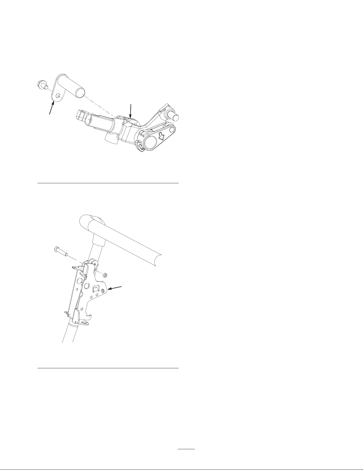
5. Remove the screw and washer securing the pin of the
traction control rod handle to the traction control
(Fig. 2). When removing the screw and washer from
lever, make sure to account for the detent ball and
spring which will fall out of the lever.
6. Remove the socket head screw and nut mounting the
traction control rod handle to the traction control lever
(Fig. 2).
1
5
32
6
4
Figure 2
1. Traction control rod handle
2. Traction control lever
3. Pin
4. Screw & washer
5. Spring
6. Detent ball
7. Remove the (4) screws securing the console to the
handle (Fig. 3). Rotate the left side of the console
downward until the right side can be maneuvered over
the traction control handle and away from the handle.
1
Figure 3
1. Console
8. Remove the cable ties securing the cables to the
control bracket.

2
9. Disconnect the throttle cable (Fig. 4) from the throttle
lever assembly as follows:
A. Unsnap the cable housing from the control bracket.
B. Unhook the cable end from the throttle lever.
1
2
Figure 4
1. Throttle control cable 2. Throttle lever
10. Disconnect the traction cable (Fig. 5) from the traction
lever assembly as follows:
A. Loosen one of the jam nuts securing the cable to
the gear box and remove the cable from the slot.
B. Remove the retaining ring that secures the traction
cable housing to the control bracket.
C. Remove the retaining ring that secures the cable
spring to the pin on the traction lever.
D. Remove the cable from the traction lever assembly.
11. Disconnect the reel control cable (Fig. 5) from the reel
control lever as follows:
A. Loosen one of the jam nuts securing the cable to
the gear box and remove the cable from the slot.
B. Remove the retaining ring that secures the reel
control cable housing to the control bracket.
C. Unhook the reel control cable spring from the reel
control lever.
1
2
3
4
5
Figure 5
1. Traction cable
2. Retaining ring
3. Traction lever pin
4. Reel control cable
5. Reel control lever
12. Remove the two screws, spacers and nuts securing the
proximity switch to the control bracket (Fig. 6). Move
the switch away from the bracket.
1
Figure 6
1. Proximity switch
3
13. Remove the screw securing the reel lever pivot pin to
the control bracket (Fig. 7).
14. Remove the reel lever pivot pin and remove the
traction/ reel control lever assembly from the control
bracket (Fig. 7).
1
2
Figure 7
1. Reel lever pivot pin 2. Traction/ reel control lever
assembly
15. Remove the (2) screws and nuts securing the control
bracket and the right end of the operator presence bail,
is so equipped, to the handle (Fig. 8).
1
Figure 8
1. Control bracket
16. Secure the new throttle/control bracket and the
operator presence bail, if removed, to the handle with
(2) M8 x 1–1/4 screws and M8 nuts (Fig. 8).
17. Mount the traction/ reel control lever assembly to the
control bracket with the reel lever pivot pin (Fig. 7).
18. Loosely mount the proximity switch to the control
bracket with (2) M6 x 1–14 screws, spacers and M6
nuts (Fig. 6). Do not tighten.
19. Connect the reel control cable (Fig. 5) to the reel
control lever as follows:
A. Hook the reel control cable spring to the reel
control lever.
B. Secure the reel control cable housing to the control
bracket with a new retaining ring.
C. Insert the cable into the slot in the gear box and
loosely tighten the jam nut securing the cable. Do
not tighten.
20. Connect the traction cable (Fig. 5) to the traction lever
assembly as follows:
A. Insert the cable onto the traction lever pin.
B. Secure the cable spring to the pin on the traction
lever with the previously removed retaining ring.
C. Secure the traction cable housing to the control
bracket with a new retaining ring.
D. Insert the cable into the slot in the gear box and
loosely tighten the jam nut securing the cable. Do
not tighten.
21. Connect the throttle cable (Fig. 4) to the throttle lever
assembly as follows:
A. Hook the cable end to the throttle lever.
B. Snap the cable housing into the control bracket.
C. Insert the cable into the slot in the gear box and
loosely tighten the jam nut securing the cable. Do
not tighten.
22. Reposition the console to the handle and secure with
the (4) screws previously removed (Fig. 3).
23. Insert the detent ball and spring inside the traction
control lever. Mount the traction control rod handle to
the traction control lever with the socket head screw
and nut previously removed (Fig. 2).
24. Secure the pin of the traction control rod handle to the
traction control with the screw and washer previously
removed (Fig. 2).
25. Secure the brake cable to the brake lever with the
screw, spacer and nut previously removed (Fig. 1).
26. Secure the reel lever pivot pin to the control bracket
with the screw previously removed (Fig. 1).
27. Secure the brake lever to the brake bracket with the
screw and lock washer previously removed (Fig. 1).
28. Adjust all the cables. Refer to the Operator’s Manual
for the adjustment procedure.
29. Adjust the proximity switch. Refer to the Operator’s
Manual for the adjustment procedure.
30. Tighten all fasteners.

Other manuals for Greensmaster Flex 21
1
This manual suits for next models
1
Other Toro TV Mount manuals


