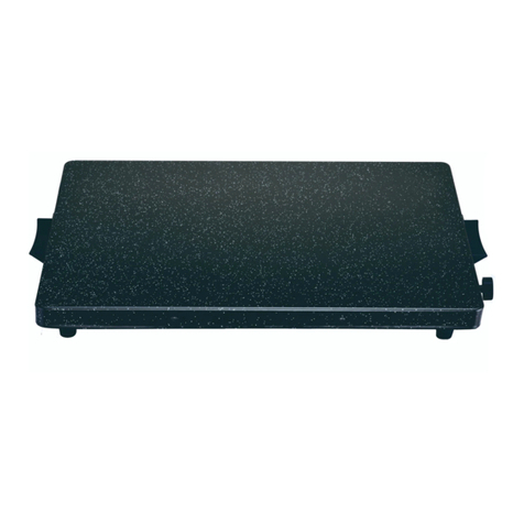
Torrey EchoTherm HP60 SERIES User manual

OPERATING MANUAL
EchoTherm™
PROGRAMMABLE HOT PLATES AND
STIRRING HOT PLATES
HP60 AND HS60 SERIES
DOCUMENT NUMBER HP60/HS60-1
Revised 17 January 2011
TORREY PINES SCIENTIFIC, INC.
2713 Loker Ave. West
Carlsbad, CA 92010
TELEPHONE: (760)-930-9400
Toll Free: 866-573-9104
FAX: (760)-930-9480
WEB SITE: www.torreypinesscientific.com
TABLE OF CONTENTS
PAGE

I. INTRODUCTION 3
II. WARRANTY 3
III. RETURN OF ITEMS 3
IV. LABELS 3
V. CAUTIONS 4
VI. GENERAL DESCRIPTION 5
VII. FRONT AND REAR PANEL CONTROLS 6, 7
VIII. SET UP INSTRUCTIONS 8
IX. DISPLAY AND KEYBOARD DESCRIPTION 9, 10, 11
X SIMPLE OPERATIONS 11, 12, 13
XI. PROGRAM OPERATIONS 13, 14, 15
XII TEMPERATURE CALIBRATION 15, 16
XIII CLEANING 17
XIV. ADDITIONAL SYMBOLS 18
XV. RS232 SERIAL INTERFACE SPECIFICATION ADDENDUM
2
I. INTRODUCTION

Congratulations on your purchase of an EchoTherm™ Programmable Hot Plate or Hot Plate/
Stirrer. Please read the instructions carefully to insure that you receive the maximum benefit
from it. Also, be sure to fill out and return the enclosed warranty registration card.
II. WARRANTY
Torrey Pines Scientific warrants this product to be free from defects in material and
workmanship for a period of one year from the date of purchase. If repair or adjustment is
necessary and has not been the result of abuse or misuse within the one year period, please
return---freight prepaid--and correction of the defect will be made without charge.
Out-of-warranty products will be repaired on a charge basis.
III. RETURN OF ITEMS
Authorization must be obtained from our Customer Service Department before returning
items for any reason. When applying for authorization, please include data regarding the
reason the items are to be returned. For your protection, items must be carefully packed to
prevent damage in shipment and insured against possible damage or loss. Torrey Pines
Scientific will not be responsible for damage resulting from careless or insufficient packing. A
15% restocking charge will be made on all unauthorized returns.
NOTE: Torrey Pines Scientific reserves the right to make improvements in design, construction,
and appearance without notice.
IV. LABELS
There are various labels on the body of this unit. Listed below are the labels and their meanings.
This symbol means: Attention. The instruction manual is to be consulted for
further information. Attention: Lire ce manuel pour des informations
complémentaries.
This symbol means: Warning, Hot Surface. Attention, surface chaude.
This symbol means: Ground or earth connection. Connexion á la terre.
3
V. CAUTIONS
HEATER PLATE SURFACE

The Torrey Pines Scientific HP60 & HS60 Programmable Hot Plates & Hot Plate/Stirrers are
capable of temperatures in excess of 450ΕC at the plate surface. Touching the heated surface
will cause severe burns. USE EXTREME CAUTION AT ALL TIMES. Never leave your hot
plate accessible to others while it is hot. Although the unit is equipped with a AHOT
WARNING@indicator on the front panel, do not rely on this alone. It is good practice to never
touch the heater surface.
NOTE: DO NOT INSTALL THIS UNIT CLOSER THAN SIX (6) INCHES (15.24 CM)
TO A WALL OF COMBUSTIBLE MATERIAL. ALSO, THIS UNIT IS NOT FOR USE
WITH FLAMMABLE SUBSTANCES.
TEMPERATURE PROBE
When attempting to control PROBE TEMPERATURE, plug in the temperature probe and place
it in the sample AT ALL TIMES. If not placed into the sample and plugged into the rear of the
hot plate, the unit will not be able to sense the temperature of the sample as heat is being applied.
This will result in driving the heater to its maximum and could result in ruining the sample.
Temperature probes vary in size and material. The most commonly used probe is the stainless
steel 6-inch immersion probe (part number HS30-600). For other probes available in other
lengths and materials, call the factory or consult your price list. All probes come with 3-foot
(91.44 cm) interconnect cable and are 3/16th (47.6 mm) in diameter. Stainless steel probes work
best with all but the most aggressive chemicals. Solid Teflon will work with the most aggressive
chemicals, but only to about 260ΕC. Glass probes are available for use with aggressive
chemicals at higher temperatures.
ELECTRICAL
These hot plate/stirrers are made in models that operate at 100, 115, and 230 volts AC ∀10%.
Be certain that your voltage matches the unit you receive. Check the nameplate on the bottom
for the voltage setting on your unit. Be certain to use a three-wire, properly grounded AC input.
Take the normal care and precaution one would use with any electrical appliance. Be careful to
keep the AC line cord away from the hot plate. Be certain to use a line cord of the same type
and rating as the one supplied with this unit. Note: all fuses are fast blow.
Bien vérifier que le cordon utilisé est du même type que celui livré avec l=unité. Note: tous les
fusibles sont à action rapide.
4
VI. GENERAL DESCRIPTION
The Torrey Pines Scientific HP60/HS60 Series Programmable Hot Plates & Hot Plate/Stirrers
are general purpose digital/programmable units. They are available with a solid ceramic top or

milled-flat cast aluminum top. All functions are settable from the digital front panel and display.
These units when received display temperature in ºC. They may be switched to read in ºF. See
page 6.
HEATER
Either the plate surface temperature or the actual sample temperature may be set. A sensor in the
plate is used to monitor surface temperature, or, alternately, a 100-ohm, 3-wire, platinum RTD
temperature probe may be connected to the rear of the unit and inserted into the sample to
measure sample temperature. When a temperature is set, power is applied to the heater to
precisely control the temperature at the plate surface or at the sample, as directed by the user.
An optional ramp value may be entered into the unit which causes the temperature to approach
the target value at a controlled rate of temperature change. This can be either an increase or
decrease in temperature. Ramp temperature is always displayed in degrees centigrade.
TIMER
All models come with a count down timer that is settable and displays in hours, minutes and
seconds. The timer can be set to 99:59:59 hours. When the timer is set it starts to count down to
zero. At zero the timer will sound an audible alarm that will ring five times. In addition to the
timer, the unit has an AUTO-OFF function. When the AUTO-OFF function is activated the
heater and stirrer will turn off at the end of any count down timer setting.
ALARMS
In addition to the audible alarm associated with the count down timer, all models have an over
temperature alarm that activates at 455ΕC on ceramic topped units and 405ºC on aluminum
topped units. If, for any reason, the plate surface temperature runs away and exceeds either
value, the units will turn on the over temperature alarm LED, sound an audible alarm, and shut
the heater off. If or when the heater plate surface cools to below 450ºC for ceramic tops or
400ºC for aluminum tops, the heater will turn on again, and the alarm LED and audible alarm
will turn off. NOTE: Failing to place the temperature probe in the solution and then setting
a probe temperature will cause the heater to heat to over 455ΕC and set off the OVER
TEMPERATURE ALARM. Also, the OVER TEMPERATURE ALARM may come on if a
very large sample is placed on the unit and a probe temperature is set. This setting can
cause the heater surface to go over 455ΕC to achieve the probe temperature set to heat the
large sample.
STIRRERS
All stirrers are a motor driven magnet which revolves directly under the heater plate. It is
normal to stir a solution while heating. A stir bar is used in the solution and couples with the
motor driven magnet and stirs the solution. 5
VII. FRONT AND REAR PANEL CONTROLS
FRONT PANEL

Shown above are the keyboard and display for the HS65 Programmable Digital Hot Plate/Stirrer.
This unit has 5-stirring positions and is the most complex unit in the series. Other models in the
series will have a single stirring position or no stirrer at all. The keypads will vary depending
upon the keys needed for the units in this series with less functions.
The front panel has a tactile touch membrane keyboard with audible feedback. The keyboard is
used to set all operating parameters. The display is a LCD type made up of rows of numbers and
several icons which function to display all parameters when the unit is running and during
setting. When the unit is turned on, the display will come on and show the actual plate surface
temperature. If a probe is used, it will display the probe temperature. The timer and stirrer
functions will show zeros.
There is a red LED on the front panel. It is actuated when the plate surface goes over 50ΕC to
remind the user that the plate surface is hot enough to cause burns. Also, it will flash when the
over temperature alarm is activated.
To change the unit from reading in ºC to reading in ºF or vise-versa hold the HEAT OFF button
down for 3 seconds. The display will switch over. The RAMP value is always set in ºC/hour
via the keypad or RS232 I/O port.
6
REAR PANEL

The AC power connector jack and fuse holder are a module mounted on the rear of the unit. The
temperature probe jack and RS232 I/O port jacks are on the rear panel as well. Note the polarity
on the probe jack. Be sure not to force this connection when plugging in the temperature probe.
The AC power jack is a three-prong, male plug combining the snap-in fuse holder. The fuse
types used appear on the label on the rear of the unit.
CAUTION: If the fuses blow repeatedly, contact your dealer or the manufacturer.
ATTENTION: Si les fusibles sautent de manière répétitive, contacter votre distributeur
habituel ou le fabricant.
The temperature sensor jack is a 5-pin DIN jack which is used with a 100-ohm at 0ΕC platinum
RTD temperature probe. Only pins 1, 3 and 5 are used.
7
VIII. SET UP PARAMETERS AND INSTRUCTIONS
The HP60 & HS60 Programmable Ho t Plates & Hot Plate/Stirrers are very simple instruments
to use. Follow the instructions below.

SET UP PARAMETERS
1. Ambient operating temperature range is from 5ΕC to 40ΕC.
2. Maximum altitude of operation should not exceed 2000 meters.
3. Maximum ambient operating relative humidity should not exceed 80% at 31ΕC decreasing
linearly to 50% relative humidity at 40ΕC.
SET UP INSTRUCTIONS
1. Place the unit on a level, dry bench or surface.
2. Plug the unit into a properly grounded, three-wire outlet of proper voltage.
3. Plug the temperature probe (if used) into the jack on the rear of the unit.
4. Place the sample on the heater plate and put the temperature probe (if used) into the sample
container.
5. Turn on the unit by the key on the front panel. The unit will beep once and the display will
light up. At this point the user can set or view any of the parameters of the unit.
6. Set either the plate or probe target temperature, stirrer, timer, ramp rate, or program according
to the instructions given in the following sections.
Note: Do not use this equipment in any manner not specified by the manufacturer.
Note: Ne pas utiliser cet équipement si vous ne pouves pas respecter les conditions
d=utilisation spécifiées par le fabricant.
ENVIRONMENTAL INFORMATION
1. This unit is for installation category II.
2. This unit is rated pollution degree 2.
8
IX. DISPLAY AND KEYBOARD DESCRIPTIONS
DISPLAY
The display has three rows of numbers and some icons. From the top they are as follows.

Plate/Probe Temperature: The icon to the left of the numbers will switch from a picture of a
probe in a vessel when the probe is in use to a flat surface with heat rays radiating up from the
surface when the probe is removed and the plate surface is being controlled. The row of
numbers to the right shows the temperature of either the plate or probe. These numbers are
normally followed with AºC@which denotes that the temperature reading is in degrees
centigrade. However, the display can be made to read in degrees Fahrenheit by holding the
HEATER key depressed for 3 seconds. When a target temperature is set into the unit, the
temperature values in the display will toggle from the target temperature to the actual
temperature. When the actual temperature is displayed, the symbol to the left of the display will
illuminate.
Stirrer: There are units in this series without stirrers (HP60 & HP61), and units with one stirrer
(HS60 and HS61), and units with five stirrers (HS65). The units without stirrers will not have a
numerical value displayed in the middle row of the display. The units with a single stirrer will
display the value of the stirrer in RPM with “RPM” to the right of the numbers. The units with
5-stirrers will display the value of the stirrer in RPM with “RPM” below a box to the right
showing which stirrer of the 5 is being displayed. The STIRRER SELECT key next to the
display can be used to move a dot around in the box next to the numerical values displayed to
choose the stirrer position being monitored. All stirrer positions can be checked this way.
Ramp: When the RAMP key is depressed the ºC symbol to the right of the top line of the display
with convert to “ºC/hr”. (The number value set in the display is always in degrees centigrade per
hour). When the value is entered for a ramp, the word “RAMP” will appear vertically on the left
of the display and it will remain illuminated as long as a ramp value is being used. This tells the
user that the target temperature as set for the probe or plate is moving from its starting point to
the target temperature at a fixed rate in degrees centigrade per hour. The ºC/Hr icon will convert
back to ºC and will be displaying only the actual and target temperatures set for either the plate
or probe. To view the ramp rate set, depress RAMP.
Timer: The bottom line of the display is the timer. The timer is displayed and can be set to
99:59:59 maximum (99 hours, 59 minutes, 59 seconds). The timer will count down to zero from
its setting and sound an audible alarm.
Auto-Off: The count-down timer can be used with an auto-off function that will turn off the
heater and stirrer when the timer counts down to zero. This function is not for use in a program,
but for use in non-programmed operation. When the AUTO-OFF key is depressed the words
AAUTO-OFF@will appear to the right of the timer value set. When this function is actuated, the
timer will count down to zero, sound the audible alarm, and turn the heater and stirrer off.
9
Program: The words PROG and a number value from 1 to 10 will be displayed to the left of the
timer value when setting a program into memory.
KEYBOARD
Power Button: This button is for turning the power to the unit on and off.

Up/Down, Right/Left Arrows: The UP and DOWN arrows to the right of the display are used to
set numeric values for the probe temperature, plate temperature, stirrer, ramp, timer, and
progressing within the steps of a program when writing or editing the program. Pushing the
RIGHT and LEFT arrows are for selecting the digit to be set.
Heater button: Touching the HEATER button is for selecting the value to be set into the heater
plate or probe. Touch HEATER then the RIGHT/LEFT/UP/DOWN arrows to set the target
temperature
Ramp Button: Touch the RAMP button is for selecting values to be entered into the ramp
function. Touch RAMP then the UP/DOWN/RIGHT/LEFT arrows to set the ramp value. To turn
off the ramp value set it to zero.
Stirrer Button (on units that have stirrers only): Touch the STIRRER button to set the value of
the stirrer. Touch STIRRER button then the UP/DOWN/RIGHT/LEFT arrows to set the
STIRRER value.
Stirrer Select Button (on multi-position stirring units only): The STIRRER SELECT button is
for use with the 5-position stirrers only. It is used with the box to the right of the stirrer numeric
values to select the stirrer to be controlled. The stirrers can all be set to one value or each to a
separate value as needed. Press STIRRER SELECT over and over and the dot in the box to the
right of the stirrer value will move around showing each stirrer position. Stop on the one to be
set and use the UP/DOWN/RIGHT/LEFT arrows to set the stirrer speed in RPM.
Timer Button: The TIMER is for setting the value of the timer. Use the
UP/DOWN/RIGHT/LEFT arrows to select the value to be set into the timer.
Auto-Off Button: Touching and releasing this button activates the AUTO-OFF function. It is
used in conjunction with the count-down timer. When activated, this will shut off the heater and
stirrer when the timer counts down to zero. This function can be turned off by touching the
AUTO-OFF button at any time during a timed event. When activated, the words AAUTO-OFF@
will be illuminated on the display.
Heater Off Button: Touching and releasing the HEATER OFF button will turn off the heater.
The HEAT OFF button also is used to change the unit temperature display from ºC to ºF and
vise-versa. Holding the key down for 3 seconds will cause the display to change.
10
Stirrer Off Button (on units with stirrers only): Touching and releasing the STIRRER OFF
button will turn off the stirrer. In the 5-position stirrer this will turn off the stirrer position
selected with the dot in the box to the right of the stirrer speed display. Depressing STIRRER
SELECT will allow the user to scroll around the box to set the dot to the selected stirrer position.
To turn off all 5 stirrers at the same time, press and hold the STIRRER OFF button until it beeps.
Edit Button: The EDIT button is used to enter the program memory to write or edit a program.

Cancel Button: The Cancel button is used to cancel a program step while writing or editing a
program or to cancel any setting if made in error.
Run Button: The Run button is used to start running a program in memory.
Enter Button: The Enter button is used to enter a value setting into the unit in manual operation
or in a program.
X. SIMPLE OPERATION
The HP/HS60 Series units are fully programmable. They have the ability to write and store in
memory ten programs of as many as ten steps each for instant recall and later use. Also, these
units can be used to set a single temperature, temperature ramp, stirring speed and timer function
without going into the memory. The memory is used for complex routines where all the
parameters of the sample can be changed automatically to other values without user attention.
TEMPERATURE
The user may enter either a target probe temperature or a target plate temperature. Only one
target temperature is allowed at one time. Setting a target probe temperature will erase any
target plate temperature previously set and vice versa. Target temperatures may be set anywhere
in the range from ambient to 450ΕC or 842ºF in ceramic topped units, or from ambient to 400ºC
or 752ºF in aluminum topped units. The unit comes with the display reading in degrees C. To
change to ºF depress and hold the HEATER OFF button until the display changes. To change
back to ºC repeat the process.
Setting Solution Temperature: When setting a solution temperature, plug the probe into the jack
on the rear of the unit and place it into the solution. With the probe plugged in, the unit will only
set and control the solution temperature as controlled by the probe. With the probe unplugged,
only the plate surface temperature is sensed and controlled by the unit. Next, touch the
HEATER button and use the UP, DOWN. RIGHT, LEFT arrows to enter the value of the
temperature wanted. Then press ENTER. The unit will now turn the heater on and drive the
solution to the target temperature. Note that the temperature display will toggle between the
target and the actual temperatures. When the target temperature is reached, the display will still
toggle but the numerical value will remain the same.
11
CAUTION: Be certain the temperature probe is in the solution when a solution
temperature target has been entered. Failure to do so could damage your sample because
the hot plate will drive to maximum while seeking a temperature it cannot find.
PRÉCAUTION D=EMPLOI: Bien vérifier que la sonde de température plonge dans le
liquide et qu=elle est connectée dans la fiche située à l=arrière de l=appareil lorsque vous
sélectionnez une température. L=échantillon risque d=être endommagé si la sonde n=est
pas connectée car la plaque va monter au maximum de sa température en recherchant une

température qui n=aura pas été.
Setting Plate Temperature: To set a plate temperature the probe must not be plugged into the rear
of the unit. With the probe unplugged, the unit will control the plate surface using a sensor built
into the heater plate and the display will show only the target and actual heater plate surface
temperatures. To set the plate temperature press HEATER and then use the UP, DOWN,
RIGHT, LEFT arrows to set the target temperature value into the display. Then press ENTER.
The unit will now drive the plate surface to the target temperature while toggling the temperature
display between the target and actual plate surface temperatures. When the target temperature is
reached, the display will still toggle between the target and actual temperatures, but the display
will read the same values.
Setting Ramp: NOTE: IF A RAMP VALUE IS TO BE USED, THE RAMP VALUE MUST
ALWAYS BE SET BEFORE SETTING A TARGET TEMPERATURE. To set a ramp
value, press the RAMP button. The display to the right of the temperature value will show
ºC/Hr. Use the RIGHT, LEFT, UP, DOWN arrows to set the selected value of ramp rate in
ºC/hr. After a target temperature is set the heater will now drive the temperature from its current
value to the target temperature, either plate or solution, at the rate just instructed. The ramp
value is always in degrees centigrade per hour even if the temperature display has been set to
read in degrees F. The RAMP rate is settable from 1ºC/Hour to 450ºC/Hour. Note that the unit
will heat fastest when not using a ramp rate setting, even 450ºC/Hour. The ramp rate
should only be used to slow the heating rate.
It is valuable to note that the ramp can be set to go up to a target temperature or down
from a higher temperature to a lower one. However, the unit can never ramp down any
faster than the sample can cool naturally. When ramping down, the heater is used to slow
a cooling rate only.
Setting Stirrer: To set a stirrer speed on single stirrer units, press STIRRER and the use the UP,
DOWN, RIGHT, LEFT arrows to set the value of the stirrer speed into the display. Then press
ENTER. The stirrer will now start to run and will display the speed in RPM on the second line
of the display.
To set the HS65, 5-position stirrer, the user can select to have all stirrers run at the same speed or
each stirrer position can be set to its own individual speed. To select the stirrers to be set use
press the STIRRER SELECT button repeatedly until the dot in the box to the right of the stirrer
12
speed display is on the stirrer position to be set. Then enter the value for that position by using
the UP, DOWN, RIGHT, LEFT arrows and press the ENTER button. That will set the selected
stirrer. Repeat this process for each position. To set all stirrers to the same speed use the
STIRRER SELECT button to scroll the dots in the box to the right of the display until all 5 dots
are illuminated. The use the UP, DOWN, RIGHT, LEFT arrows to enter the stirrer speed value,
and press the ENTER button.
Setting Timer: To set a timer value press the TIMER button and use the UP, DOWN, RIGHT,
LEFT arrows to set the value in hours, minutes and seconds. Then press the ENTER button. The

timer will now start to count down toward zero. When the timer reaches zero it will sound the
audible alarm. To stop the alarm press CANCEL.
Setting Auto-Off: The auto-off function is used with the timer. When activated, the unit will
turn off the heater and stirrer when the timer counts down to zero. To set the auto-off function,
press the AUTO-OFF button. The display will illuminate the words AAUTO-OFF@to the right
of the timer telling the user that the auto-off function is set. To turn off the auto-off function,
touch the AUTO-OFF button again. The words, AAUTO-OFF@will no longer be illuminated in
the display. Remember that when AUTO-OFF is on, the unit will automatically turn off the
heater and stirrer when the timer counts down to zero.
XI. PROGRAMMABLE OPERATION
The HS60 series have the ability to store ten programs in memory for instant recall and use.
Each program has ten steps maximum where one step is a temperature, stirring speed, ramp
function (if wanted), and time. At the end of each program there is a cycle step that can be
selected to repeat the program up to 98 times. Setting cycles to 99 makes the program repeat
infinitely. These programs are stored in CMOS and cannot be lost by a power failure or by
turning the unit off. However, if power fails during a program run, when power returns, the unit
will have lost its instructions and will be sitting with the same information on the display as
when the unit was first turned on. To stop a program while it is running touch CANCEL.
Some rules for programming:
To erase all programs in memory, depress and hold the EDIT key for about 5 seconds. The
display will be all blank. When the EDIT key is released, after a few seconds or, the
display will return to the normal screen and the programs will be erased. This erases ALL
programs in memory. To change or erase one program the user must go into the program
and remove each step.
The timer can be used in two ways in a program. The timer can be used with a ramp
function or without a ramp function. When the timer is used with a ramp function, the
timer does not start to count down until the target temperature is reached. When the timer
is used without a ramp function, the timer starts to count down as soon as the program
starts. If the user wants a timed event to start after the target temperature is reached, but
13
does not want to wait for a ramped approach to the target temperature to take place, set
the ramp to 450. In almost all cases, this ramp rate is faster than the unit can approach the
target temperature, and it will appear as though no ramp rate is being used, and the timer
will start to count down after the target temperature is reached.
RUNNING A PROGRAM STORED IN MEMORY
1. Press RUN. The display will show PROG 1 at the bottom of the display to the left of the
timer. This is program 1.
2. If program 1 is the choice to be run, next press ENTER. Program 1 will now start to run. If

program 1 is not the choice use the UP ARROW to scroll to the program of choice. When the
program is chosen, press ENTER and the program stored in that site will start to run. As the
program starts to run, as the unit progresses through the steps in the program, the audible
alarm will sound five times for each step as the program progresses. As the program moves
through the steps in the program the current step will be displayed to the left of the timer.
HOW TO WRITE A PROGRAM
Remember, a program step is a temperature, stirring speed (if wanted), temperature ramp
(if wanted), and a timer setting. Do not advance to the next step until the current one is
complete.
1 Press EDIT
2 Select the program site (1 through 10) using the UP and DOWN ARROWS.
3 Touch ENTER. The display will show PROG 1 for program one step one.
4 Enter the ramp value if wanted (remember how the timer works with and without a ramp
function) and push the ENTER button. Then enter a temperature and push the ENTER
button, and stirring speed and the ENTER button, and the time function for that step and
ENTER button. This step is now finished.
5 Press the UP ARROW to go to step 2. The display will show 2 for program step two.
Now enter the values for ramp, temperature, stirrer and timer being certain to hit ENTER
after each. Step 2 is now complete.
6 Repeat the steps above until the program is written.
Note: If a mistake is made while entering a program step, just hit CANCEL on that
step and make the new entry. To go back to a prior program step, hit the DOWN
ARROW. Likewise, to go forward to another program step, hit the UP ARROW.
7 After the last program step data has been entered, press ENTER twice. The display will
now show CYC 01. If only one cycle of the program is needed, hit ENTER. If more
than one cycle of the program is wanted, use the UP ARROW to go to the number of
cycles wanted. For example, twenty cycles would appear on the display as CYC 20.
Then press ENTER again and the program is written and stored for use.
14
8 To run a program, press RUN, the display will show PROG 1. To run program 1, press
ENTER. To select and run a different program, use the UP ARROW to scroll to the
program to be run, and press ENTER.
XII. TEMPERATURE CALIBRATION
The HP/HS60 series are designed for accuracy. The temperature calibration designed into the
unit is made to hold for very long periods of time. When calibrated in the factory, it is expected
that the unit will meet the most demanding customers=requirements. However, our standards

for temperature measurement may not be the same as the users. Therefore, the HP/HS60 series
has been designed to be calibrated in the field by the user. Follow the instructions below if
calibration is wanted or needed.
Note: To calibrate the unit the user is advised to remove all previously entered calibration data.
To erase the calibration and return to not calibrated readings, press and hold the HEATER button
for three seconds until the display reads CAL. Then press and hold the CANCEL button for
three seconds. Calibration is erased independently for the probe and the plate depending upon
whether the probe is plugged in or not.
PROBE CALIBRATION
Probe calibration is performed by using an accessory calibration kit which precisely simulates
fixed temperature points. The kit has two dummy probes which, when plugged into the probe
jack, represent the value of resistance equal to the temperature shown on the dummy probe. The
dummy probes represent temperatures of 25ΕC and 400ΕC. These are the probe calibration
points. The kit is available from the manufacturer (HS30-700).
To calibrate the probe temperature, follow these steps.
1. Insert the 25ΕC dummy probe in the probe jack at the rear of the unit. Depress and hold
the HEATER button for 3 seconds until the display reads CAL. Then press ENTER.
Then use the UP/DOWN/RIGHT/LEFT arrows to make the display read 25ºC. Then
press ENTER. The probe low calibration point is now calibrated.
2. Remove the 25ΕC dummy probe and replace it with the 400ΕC dummy probe. Depress
and hold the HEATER button for 3 seconds until the display reads CAL. Then press
ENTER. Use the UP/DOWN/RIGHT/LEFT arrows to make the display read 400ΕC.
Then press ENTER. The probe high calibration point is now set.
3. Remove the dummy probe. The probe calibration is now complete.
15
PLATE CALIBRATION
The plate calibration does not affect the probe calibration and vice versa. If you are using the
probe temperature control loop only, it is not necessary to calibrate the plate loop. The plate
loop has been factory calibrated and is not likely to change.
To calibrate the plate, an accurate digital temperature meter and a surface temperature probe are
needed. This is a very difficult measurement to make, and not all surface temperature probes
will do the job well. If you need help, please contact the factory. The Plate and Probe
calibration kit #HS30-800 is available from the factory and will contain the temperature meter,
probe, and dummy probes for the probe calibration.

The plate surface calibration procedure cannot be done with the temperature probe
plugged into the rear of the unit.The calibration starts at the low temperatures and goes high.
It is time consuming. Before making an adjustment, be sure that the plate temperature has
stabilized at the point being calibrated. That often takes 20 to 30 minutes after the target
temperature is initially reached. Follow the procedure below.
1. Start at room temperature. Using your temperature meter, read the plate surface
temperature in the center of the heater plate. Press and hold the HEATER button for 3
seconds until the display reads CAL. Then press the ENTER button. Use the
UP/DOWN/RIGHT/LEFT arrows to input the temperature measured for the plate
surface. Then press the ENTER button. The plate low calibration point is set.
2. Set the PLATE temperature to 350ΕC. The plate will start to heat. Give the unit ample
time to reach and stabilize at 350ΕC. When the temperature is stable, measure the plate
temperature with your meter. Press and hold the HEATER button for three seconds until
the display reads CAL. Then press the ENTER button. Use the
UP/DOWN/RIGHT/LEFT arrows as needed to make the plate temperature display read
what is measured on your meter. Then press the ENTER button.
3. Let the unit cool back to room temperature. It will take some time. You can speed the
process by using a fan to help cool the plate. After about an hour measure the plate
surface temperature again. Then reset the plate temperature to what the meter reads as
was done in step 1 above.
The plate surface calibration is now complete.
16
XIII. CLEANING, MAINTENANCE, AND CONSUMABLE PARTS
Cleaning
These units are subject to splashes and spills during normal use. Be sure to clean all spills
quickly. Wipe spills with a soft cloth or paper towel. If a cleaning solution is necessary, use a
mild soap or detergent solution and a soft cloth. Be sure not to use solvents. They could damage
the paint, labels or display window on the unit. A mild abrasive can be used to clean the ceramic
glass heater surface. Do not use abrasives on the cast aluminum heater top. It will scratch the
surface.
Note: When using these units with corrosive liquids, the vapors coming off these liquids
may get into the chassis of the unit and cause damage. This is particularly true on the 5-

position stirring units, the HS65. This unit has a fan on the rear of the unit too cool the
stirrer motors. Vapor can be drawn into the unit by this fan. In any case when using
corrosive chemicals, it is best to try to purge the unit using lab air or an inert gass. Plug as
many holes as is possible and run the gas line into the unit. This causes a positive air
pressure inside the unit and helps keep corrosive vapors out of the unit. On the HS65, the
user may want to deactivate the cooling fan when using a purge gas. When using the unit
with corrosive gasses always work under a fume hood.
CAUTION: Do not attempt to clean the heater surface when it is hot. Burns could occur.
PRÉCAUTION D=EMPLOI: Ne pas nettoyer la surface de la plaque lorqu=elle est chaude
pour éviter toute brûlure accidentelle.
Maintenance
There is no ongoing maintenance program needed with this unit other than the normal care and
cleaning as instructed above and a simple inspection done whenever the unit is to be used. This
simple inspection should include:
1- Checking that the AC line cord is not frayed or burned.
2- Checking that the unit is not dirty to a point where proper performance is impaired. This is
especially important relative to the membrane switch and LCD window.
3- Being certain to store the unit properly when not in use in an area that will not have items
placed on top of the unit. Cover the unit in a way that will keep dirt and other foreign bodies
out.
17
XIV. ADDITIONAL SYMBOLS
The following are additional symbols found on the labels of the instrument.
Symbol Description
V Voltage
~ Alternating Current
A Current
Hz Frequency
W Power
F Fast Acting Fuse
T Time Delay Fuse
I Mains On

O Mains Off
XV. RS232 SERIAL INTERFACE SPECIFICATION
(See the following pages)
18
This manual suits for next models
1
Table of contents
