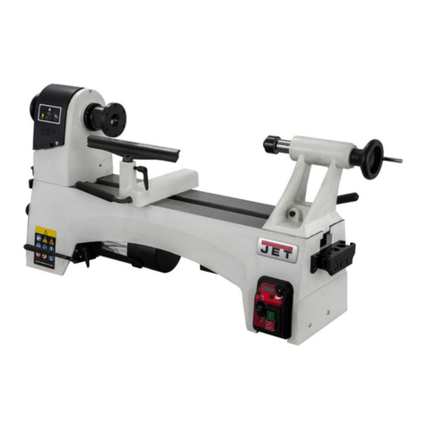
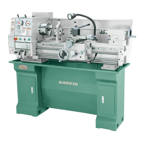
TOS SUA 125 NUMERIC User manual

SUA 125 NUMERIC
UNIVERSAL CENTRE LATHE
SUA 125 NUMERIC
(VERSION WITH AUTOMATIC SHIFT OF REVOLUTIONS)
OPERATING INSTRUCTIONS
TOS a.s.

SUA 125 NUMERIC
T
TO
OS
S,
,
a
a.
.s
s.
.
Member of the CTY GROUP
Stankovského 1892
250 88 Čelákovice
Czech Republic
YOUR PARTNER FOR SOLUTION
OF TECHNICAL PROBLEMS
IN TURNING OF WORKPIECES
Commercial section Service section
Tel.: +420 296 583 213 Tel.: +420 326 633 230
Fax: +420 296 583 226 Fax: +420 326 633 259
e -mail: sales@tosas.cz
e -mail: [email protected]z
http://www.tosas.cz

SUA 125 NUMERIC
34200003 TOS a.s. 02/2011
- 3 -
Opening Word of General Manager.
Dear operator of the SUA 125 NUMERIC centre lathe.
I have pleasure in submitting this Manual to you which will inform you of:
- charakteristics for use
- service
- maintenance
- safe and hygienic operation of SUA 125 NUMERIC universal centre lathe.
The performance of the SUA 125 NUMERIC; centre lathe and this Manual, are full in
harmony line with the instructions and valid Standards for machinery in member states of the
European Union (hereinafter called EU). For this reason the machine will certailny find its place
in the European market and can be marked CE (Conformité Europeénne).
If you follow all instructions contained in this Manual you will be satisfied with the high-quality
of this machine.

SUA 125 NUMERIC
34200003 TOS a.s. 02/2011
- 4 -
This Manual is intended only for the SUA 125 NUMERIC / 2000
centre lathe of serial number mentioned below.
Order number: 34200003
Customer:
SERIAL NUMBER OF LATHE:
34200003
Serial number must be stamped on the front bed part of lathe and on the right hand end of an active surface (in tailstock
part) and should be mentioned in all instructions concerning the lathe. This serial number should be used in dealings of all
relations between customer and manufacturer.
INVENTORY NUMBER OF LATHE:

SUA 125 NUMERIC
34200003 TOS a.s. 02/2011
- 5 -
1. Contents.
1. CONTENTS......................................................................................................................................................................5
2. BASIC INFORMATION FOR USER OF SUA 125 NUMERIC UNIVERSAL CENTRE LATHE. ......................7
2.1. PREFACE. ........................................................................................................................................................................7
2.2. FORM OF MANUAL ARRANGING. ....................................................................................................................................8
2.3. ANALYSIS OF RISK FACTORS ...........................................................................................................................................9
2.4. CONCEPTION VERSION OF SAFETY DEVICES OF THE SUA 125 NUMERIC LATHE WITH NUMERICAL CONTROL SYSTEM
ACCORDING TO EU STANDARDS. ..............................................................................................................................................14
2.5. UNIVERSAL SAFETY,ECOLOGICAL AND HYGIENIC DEMANDS APPLIED TO CONCEPTIONAL LATHE VERSION OF SUA 125
NUMERIC WITH EU STANDARDS............................................................................................................................................17
2.6. GENERAL DATA CONCERNING CENTRE LATHE WITH CNC CONTROL..........................................................................20
3. SPECIFICATION OF MACHINE. ................................................................................................................................26
3.1. BASIC DATA..................................................................................................................................................................26
3.2. SPECIFICATION OF ELECTRIC EQUIPMENT.....................................................................................................................32
4. PURPOSE OF USE OF SUA 125 NUMERIC LATHE. .............................................................................................33
4.1. REQUIREMENTS FOR LATHE OPERATOR CONNECTED WITH PERSONAL SAFETY..............................................................33
5. DESCRIPTION OF MAIN ASSEMBLIES OF SUA 125 NUMERIC CENTRE LATHE FROM POINT OF
VIEW OF THEIR FUNCTIONS..........................................................................................................................................37
5.1. GENERAL PRINCIPLES....................................................................................................................................................37
5.2. SPECIFICATION OF FUNCTIONAL ASSEMBLIES OF LATHE (FIG.5.1) ..............................................................................38
5.2.1. Bed .......................................................................................................................................................................38
5.2.2. Driving Section.....................................................................................................................................................40
5.2.3. Brake. (Fig. 5.2)...................................................................................................................................................43
5.2.4. Headstock.............................................................................................................................................................47
5.2.5. Gearbox................................................................................................................................................................47
5.2.6. Work spindle.........................................................................................................................................................48
5.2.6.1. Reducing taper ................................................................................................................................................................... 52
5.2.7. Ball circulating lead screw...................................................................................................................................53
5.2.8. Carriage, ..............................................................................................................................................................53
5.2.9. Tailstock (fig. 5.6):...............................................................................................................................................56
5.2.9.1. Load of clamping centre in dependence on overhang of tailstock sleeve.......................................................................... 61
5.2.10. Liquid Circuits......................................................................................................................................................62
5.2.11. Lubrication circuit................................................................................................................................................66
5.2.12. Cutting lubricant circuit.......................................................................................................................................69
5.2.13. Rests .....................................................................................................................................................................83
6. DESCRIPTION OF SAFETY DEVICES. ...................................................................................................................85
7. ACOUSTIC EMISSION DATA....................................................................................................................................86
8. OTHER EMISSION DATA..........................................................................................................................................87
9. TRANSPORT OF LATHE............................................................................................................................................88

SUA 125 NUMERIC
34200003 TOS a.s. 02/2011
- 6 -
9.1. MANIPULATION.............................................................................................................................................................88
9.2. DIMENSIONS AND MASS OF THE LATHE (FIG.9.2)..........................................................................................................90
10. ERECTION OF LATHE AND ITS PUTTING INTO OPERATION...................................................................91
10.1. BUILDING OF FOUNDATION. ......................................................................................................................................91
10.2. ERECTION ON FOUNDATION......................................................................................................................................91
WORKING AREA........................................................................................................................................................................96
10.3. OPERATING POSITION................................................................................................................................................96
10.4. ADMISSIBLE CONDITIONS OF SUROUNDINGS: ............................................................................................................96
10.5. CONDITIONS FOR CONECTION OF MACHINE TO MAINS:(MAINTENANCE) ...................................................................96
10.6. ENSURING OF ECOLOGICAL CONDITIONS:..................................................................................................................97
10.7. THE PREVIOUS MEASURES FROM THE USER PART. .....................................................................................................97
11. DETERMINATION OF SERVICE PROCEDURES TO ACHIEVE OF WORKING CAPACITY OF
FUNCTIONAL ASSEMBLIES. ...........................................................................................................................................98
11.1. BASIC INFORMATION FOR THE LATHE SERVICE..........................................................................................................99
11.1.1. Running-on on reference points .........................................................................................................................100
11.2. BASIC PROCEDURES FOR LATHE SERVICE ................................................................................................................102
11.2.1. Reference (home) points approaching................................................................................................................102
11.2.2. Spindle control ...................................................................................................................................................103
11.2.3. Control of carriage movement ...........................................................................................................................103
11.3. LATHE OUTPUT UTILIZATION (FIG.11.1)..................................................................................................................104
11.4. LONGITUDINAL AND TRANSVERSAL STOPS..............................................................................................................107
11.4.1. Transversal stops................................................................................................................................................107
11.4.2. Longitudinal stops..............................................................................................................................................107
12. MAINTENANCE AND TESTING OF LATHE....................................................................................................111
12.1. INSPECTION.............................................................................................................................................................111
12.2. MAINTENANCE........................................................................................................................................................111
12.3. USING SAFEGUARDS................................................................................................................................................111
13. OPERATION BREAKDOWN................................................................................................................................112
14. DATA FOR URGENT HELP. ................................................................................................................................113
15. THE REST................................................................................................................................................................114
16. DETERMINATION OF THE TORQUE MOMENT MK FOR THE GIVEN CUTTING CONDITIONS
ACCORDING TO THE MOTOR OUTPUT.....................................................................................................................115
17. CONCLUSION.........................................................................................................................................................118

SUA 125 NUMERIC
34200003 TOS a.s. 02/2011
- 7 -
2. Basic Information for User of SUA125 NUMERIC Universal Centre Lathe.
2.1. Preface.
This Manual of the SUA 125 NUMERIC centre lathe (hereinafter called Manual) is set up in accordance with “The
Directive 89/392/EEC“ of June 14, 1989 (hereinafter called Directive) which gives basic demands on safe, hygienic and
ecological machinery operation in the states of “European Union“ (hereinafter called EU).
This Directive embodies each machine put on the market in the EU states see Directive, SUPPLEMENT I part 1.1.2
and 1.7.4.
The directive refers in its single chapters to Directives and EU Standards. All these demands are reflected in this Manual.
Note:
According to the Directive, the following EU Standards were used:
A type (basic safety Standards)
B type ( a collection of safety Standards)
B1 engaged in safety points of views (safe distances, etc.)
B2 engaged in safety devices (locking devices, covers, etc.)
C type (safety Standard for machinery - machine tools).
According to the Directive, the following definitions are mentioned in this Manual:
- “dangerous space“ any area inside and about lathe where a person is run to risk of dangering someone
health and safety,
- “exposed person“ person situated in or partly in the area of action where the risk can come into existence,
- “operator“ is a person or persons carrying out an instalation, service, maintenance, cleaning, repairs or lathe
transport.
The EU demands in this Manual are enlarged of ones which are apply to the safety machine operation in the Czech republic.
All demands mentioned in this Manual should be respected by the operator in the interests of safety of operation.

SUA 125 NUMERIC
34200003 TOS a.s. 02/2011
- 8 -
2.2. Form of Manual Arranging.
Instructions for operator, data of maintenance and tests, information of possible lathe out of operation together with
analysis of operational safety conditions are arranged in this Manual by:
- functional and service description
- instructions for the operator (Manual)
- instructions for maintenance carried out daily by the operator for ensuring the operation capacity.
- instructions for ensuring the maintenance by qualified person
- instructions for service ensuring by the manufacturer
- recommended technological turning process
- testing procedure for checking the lathe accuracy
- conditions for installation and mounting
- transport procedure
- instructions for lubrication
- catalogue of spare parts
Instructions and description in this Manual have been set up with the aim of limiting the risk factors to the minimum,
mentioned in the EU Standard - EN 292 "Safety of machine devices".
The survey is tabulated in the following tables.

SUA 125 NUMERIC
34200003 TOS a.s. 02/2011 9
2.3. Analysis of risk factors
Risk factors in accordance with
EN 292
Risk situation.
Activity.
Dangerous space.
Other references.
Number. Name.
1. Mechanical risks:
1.1. Crush risk (compression).
Workpiece clamping .
Workpiece change. Tool change.
Between clamp (jaws) and
workpiece.
Tool clamping.
Tool post change in position.
In tool post and within the zone of
tool motion cover.
1.2. Shear risk.
Moving carriage.
Enter into the working space.
Between carriage and bed.
1.3. Cut or cut off risk.
Rotating spindle or moving tool.
Lathe operating mode.
Path of tool edge travel.
Workpiece surface.
1.4. Catch risk.
Chip removal.
Chip removal.
In the sphere of cutting proces.
1.5. Draw or grip risk.
Carriage rapid travel or workpiece motion.
Power operated carriage or
workpiece motion.
Carriage, tool and workpiece
motion cover.
1.6. Impact risk.
Moving tool.
Tool feed.
Tool motion cover.
Workpiece handling.
Workpiece exchange.
Working space.
1.7. Shoot risk.
Shooting of material parts and chips.
Machining process control.
In machining proximity.
1.8. Risk of tripping, slipping and falling.
Spirting, pooling of cutting lubricant and
lubricating or hydraulic oil chips flushed by
cutting lubricant.
In or after process.
After or in maintenance.
Floor surface round the lathe.
2. Electric risks produced by:
2.1. Contact.
Direct and indirect contact.

SUA 125 NUMERIC
34200003 TOS a.s. 02/2011 10
3. Heat risks:
No heat risks are occurred.
4. Noise risk with consequent:
Noise metering record.
4.1. Reduction of hearing
Motion of power and geared parts. Cutting
process. Noise resonance of machined material.
In course of machining.
In lathe proximity.
5. Vibration risks:
Vibration metering record.
6. Radiation risks:
Unrelated.
7. Risks caused by machined
materials and liquids used in
machining process:
7.1. Contact or inhalation of harmful
vapours of liquid, gas, mist, smoke and
dust.
Conditions in lathe proximity caused by
particles of machined material, drops of cutting
lubricant or arised mist
In course of machining
In lathe proximity.
7.2. Fire or explosion risk
Flammable machined material.
Mist making
Loss of cutting lubricant supply to the point of
machining. In line breakdown to the power
electric hydraulic or lubricant systems
In course of machining
In lathe proximity.
7.3. Biological and microbiological
risks
Contact with hydraulic or cutting lubricant
either in liquid state or in mist which consists of
chips,bacteria e.t.c....
In course of the working
process control and in
maintenance
In lathe proximity.

SUA 125 NUMERIC
34200003 TOS a.s. 02/2011 11
8. Risks caused by neglecting of
ergonomical principles:
8.1. Unhealthy possitions or excessive
working stress.
Lifting and handling of materials
machined, tools and lathe parts.
In course of loading and unloading,
working process control and
maintenance.
In places of loading, unloading, tool
fitting position and in maintenance
places of action.
8.2. Amission of using the personal
protective aids.
Details mentioned in
Manual.
8.3. Disproportionate space lighting.
Premeditation and precision of manual
activity are weakened in the handling with
materials or tools or in their positioning.
In loading, unloading, controlling,
watching and tool handling.
In proximity of loading, unloading
and tool fitting positions.
8.4. Human mistake.
Logical foreseeable wrong use. Inattentive
control. Wrong handling with material
processing and tools and their setting up.
In course of loading and unloading,
in course of working process
control and tool handling.
In proximity of loading and
unloading positions and fitting
positions.
9. Combination of risk factors:
Non - existent.

SUA 125 NUMERIC
34200003 TOS a.s. 02/2011 12
10. Risks caused by electric power
supply brake, damage of lathe parts
and other function defects:
10.1. Electric power supply brake.
Lathe control failure with consecutive wrong
use of accumulate energy.
Electromotor overspeeding: Moving parts
failure under the influence of residual forces
which cause unexpected movement of external
parts.
In the course of work, working
activity control and maintenance.
At lathe and its parts which are kept
in safe position by causing of force
or liquid pressure.
10.2. Unexpected flinging of lathe
parts or spirting of lubricant.
Electric motor overspeeding. Tool fraction.
Hydraulic system failure. Breakage or spirting
of lathe parts under the influence of residual
forces.
In course of machining.
In lathe proximity.
10.3. Failure, wrong function of
control system.
Unrelated.
10.4. Assembly error.
Machine parts are displaced unexpectedly or
fallen down.
In course of working activity
control and in tool fastening. In
the course of maintenance.
At lathe.

SUA 125 NUMERIC
34200003 TOS a.s. 02/2011 13
11. Risks caused by missing of wrong
located agents seccuring with safety of
work:
11.1. All kinds of covers
Drive cover
spindle measuring cover
lead screw cover
longitudinal feed cover
front cover - fast
front cover - movable
real cover.
1 60 4891
1 45 8629
3 08 8049
3 08 8097
1 70 3081
1 60 9903
2 60 9666
11.2. All kinds of corresponding safety
devices
Detailed description of safety devices is
comprised in PLC description.
See the following survey of
safety and emergency
switches.
11.3. Starting and stopping devices.
These functions are set by control
system.
11.4.Safety marks and rating plates.
Lids and covers of electrical equipment
are marked with black lighting on
yellow base.
11.5. All kinds of devices of information
and warning
Rating plate of pressure setting.
11.6. Power supply failure devices
Main switch of circuit breaker.
11.7. Emergency devices
Lathe running.
Emergency stopping.
Emergency stopping device.
Push button.

SUA 125 NUMERIC
34200003 TOS a.s. 02/2011 14
2.4. Conception version of safety devices of the SUA 125 NUMERIC lathe with
numerical control system according to EU Standards.
The main dangerous working space is:
-working area with rotating spindle, with moving components for chucking of workpiece e.g.chuck or face-plate and things
moving with carriage tool and workpiece.
Safety requirements and measures .
Risk limitation of construction is carried out in accordance with EN 292-2 , article 3 and protective devices are in
accordance with EN 292-2, article 4.
Control system in general.
It complies with EN 292-2, article 3 subarticles 3.7 and 3.10 and further articles from 5.1.1 to
5.1.10.
Safety and reliability of control system
Includes everything from starting of an actuator and a position sensor in the place of input to final driving device,
electric motor.
From the standpoint of safety the control system ensures:
-starting and repeated starting
-operating stop
-spindle rotation (including rotation with limited speed)
-emergency stop
-blocking
-blocking with locking of protective shields
-feeds (including limited feed rates)
-no arresting actuators (they must be pushed down continuously)
-workpiece chucking
Control system is of the 3rd category in accordance with EN 954, article 7.2.
Position of actuators .
The main contol devices for starting,operating stop and selection of lathe modes and no arresting actuators, are placed in the
operating point near the movable protective shields and actuators and they are in accordance with EN 894-1-2-3.
Starting
See EN 60204-1, articles 9.2.5.2.
The function of starting actuator is controled by mode selection (see paragraph“Change-over switch for mode selection“).
Safety functional protection is reached by block arrangement (see paragraph“Production mode“and “Adjusting mode“).
Closing of movable protective shields does not result in automatic repeated start of movable components.
When the protecive shields are open an unexpected start of dangerous motions of spindle or face-plate, workpiece and tool
are prevented in accordance with EN 1037.
Operating stop
The operating stop is set for ensuring the operating mode. Power supply to el.motors for drive in single
coordinate axes controled by CNC system (category 2 in accordance with the article 9.2 from EN 60204) is not
disconnected if the operating stop is activated, because there is a separated power control of working
spindle.The lathe stop is reached after control acting in dependence on workpiece mass and activity mode of CNC system. If
the lathe is stopped by operating stop, the opening of protective shields keeps the lathe stop in category 2 (see EN 60204,
the article 9.2).
It is posible to repeat start in the operating mode only if the protective shields are closed.

SUA 125 NUMERIC
34200003 TOS a.s. 02/2011 15
Emergency stop
Emergency stop corresponds to EN 60204, the article9.2.5.4 and EN 418, an actuator is located on the main control panel
and panel operated movement of tailstock.
Change-over switch for mode selection
The lathe is equipped with the mode switch which can be selected as “Operating mode“ as “Adjusting mode“. The selection
of modes ensures that in every time is only one active mode. The safety protection is effective in any mode.
Operating mode
If the moveble protective shield with blocking device is open in the operating mode it is only possible to open and close the
clamping device. Operating motions are possible when the moveable protective shields with blocking device are closed.
Moveable protective shields are equipped with blocking devices in accordance with EN 10888, article 3.3.3.4. and in
accordance with EN 292.2, article 4.2.2.3.
Adjusting mode
- is attainable by lockout change over switch of mode
- makes an approach to the cuting space possible when the protective shields with blocking device are closed on the
following conditions: feed rates are limited to a speed up to to 2 metres per minute and are controled by no arresting
actuator in any axis or they are limited to stepping motion with the lenght of the step not longer than 6 mm.
Note: The function “Block by block“ and progamme motion are impossible in this mode.
The following conditions are applied for the lathe:
- spindle rotation is possible only in revolutions of 50 r.p.m. or less and if the no arresting actulator is used.
Limited speed control
Control system connected with the safety for limited speed is in category 3 in accordance with EN 954-1.
For limited speed control by means of software two separated software canals have got a computer control with cross check.
For supplying the requirements of category 3 the control (excessive) loops for the acceleration check, threshold speed
check, etc. are used in above mentioned control.
Numerical control
Numerical control is self-checking, capable to comparison of input and output data which are protectived against possible
loss of programmes and electromagnetic effects and it is constant at error exposures of electric system.
Software connected with any safety should not be adjusted by user.
Power supply failure
It is secured by means of undervoltage protection device, which prevents an automatic repeated starting ( see EN 60204-1,
the article 7.5.).
Protection against mechanical risk factors
See description EN 292-1, the article 4.2 and principles EN 292-2, the article 4.

SUA 125 NUMERIC
34200003 TOS a.s. 02/2011 16
Working area
The conditions for workpiece chucking.
In general.
No workpiece clamping devices are controllable if the spindle is rotating. Work clamping device is equipped with a
protective shield for supplying of EN 293 requirements.
Programm will not run in operating mode sooner until the following conditions are fulfilled:
a) max. spindle speed for machining every rebound is set and displayed
b) the max. admissible revolutions of lathe chucking device are preselected.
c) the power applied on the tailstock sleeve is checked.
Manual device
There are means which can stop the spindle starting if a wrench is pushed into the chuck or a crank into the face-plate.
Throwing up
Working area is covered with a protective shield which minimalizes to throw workpieces, machine components, tools or
their parts, chips and cutting lubricant up.
Approach to the working area
To avoid acting risk factors mentioned in EN 292-1, the article 4.2 (drawing in, clamping, cut, etc.) there is a limitation of
approach to the dangerous parts, for example rotating chuck (chucks), face-plate and spindle (spindles) power operated
tools, moving parts of lathe in coordinate axes and drives, by means of a protective shield. The protective shield prevents
from approaching to the working area and also serves as a shield which minimalizes a risk of throwing up.
Drives protection
Drives ( for example indented belt drive) are covered with fast protective shield.
Blocking with protective shields
Moving protective shields which prevent an approach to the dangerous spaces of lathe motions are equipped with blocking
devices. The selection of blocking device is in accordance with EN 1088, the article 7.1.. The blocking error causes the lathe
stop -see 1 cathegory according to EN 60204-1, the article 9.2.2..
Blocking device with locking of protective shield (see EN1088 and EN999). Moving protective shields will keep clossed in
operating mode until the lathe stops. The other safety devices and means as limited spindle speed are in function of
adjusting mode.
Demanded characteristics of protective shields
In general.
Protective shields fulfil the EN 953 Standard.
Protective power - operated shields
Protective power - operated shields are in accordance with EN 292-2, the article 4.2.2.6..
Displacement
There are means and information for releasing of catching persons at lathe for examle it is possible to move the set part
manually (not by machine) - see EN 292-2, the article 6.1.2..

SUA 125 NUMERIC
34200003 TOS a.s. 02/2011 17
2.5. Universal safety, ecological and hygienic demands applied to conceptional lathe
version of SUA 125 NUMERIC with EU Standards.
Noise.
There are suitable means to minimalize risks cased by noise, for example decrease of supply noise or absorption of emitting
noise.
If the conditions for noise test are not at disposal, the noise declaration gives following data:
- arrangement and lathe working conditions in case of measuring of emitting noise.
- position of working place where the levels of acoustic pressure were measured.
- method used for measuring
- tests according to them the declaration of noise level is worked.
Information of noise spreading by air is mentioned in accordance with used measuring methods and in accordance with
working conditions specified in relevant EN National Standards.
Note:
Noise measuring is worked according to the Czech National Standard NSST 20 102 “Noisiness of metal machine tools“.
Lighting
Lighting of working area is worked such a way so that the motion of cutting process could be visible through the inspection
hole and its intensity should be at least 300 luxs measured before the end of work spindle at the distance corresponding to
chuck diameter.
Electrical equipment
Electrical equipment is pursuant to EN 60204-1.
Ergonomy
The lathe is designed in accordance with ergonomical principles mentioned in EN 292-1, the article 4.9, EN 292-2, the
articles 3.6 and 6.2.4, EN 547-1 and 2 and ENV 26385.
Where there is a device for workpiece handling required a measure for their instalation and activity is possible in open
shields, e.g. by forming approach from the top of the machine, by lifting mechanizm, etc..
Cutting lubricants
The lathe is designed to enable a maintenance of cutting lubricant, e.g. to take samples, cleaning of tanks and tubes and
filter exchanche so that a leakage, pouring and possible contact with lubricant, etc. are prevented.
Tanks and tubes for cutting lubricant are designed such a way so that the place with immovable lubricant is not occured
during circulation.
Hydraulic system
To avoid risks arising from hydraulic system the lathe is made in accordance with EN 982.
Disconnection
See EN 292-2, the articles 3.8 and 6.2.2.
An electric disconnecting switch is in accordance with the article 5.3 in EN 60204-1 ( disconnecting switch is not the d type
) in the article 5.3.2.
Maintenance
See EN 292-2, the article 3.12 and the supplement A, EN 292-1, the article 1.6.1.
The information of maintenance in examples according to EN 292-1, the article 5.5.1 is mentioned in this Manual.

SUA 125 NUMERIC
34200003 TOS a.s. 02/2011 18
Safety information
It is in accordance with EN 292-2, the article 5 in this Manual.
Marking
clamping device of workpiece (face plate) is marked with the max. admissible speed.
Manual
This Manual is in accordance with EN 292 demands, the article 5.5.
The following data are mentioned in this Manual and selling literature:
- noise emission values
- principles of test making
- general safety principles for the lathe operation.
Tool exchange
The information which allows safety chucking and tool exchange is mentioned in this Manual, e.g. data refering to this part
of dividing line tool - machine, which belongs to the lathe.
Exchange of workpiece chucking device
This Manual contains the information which allows the safety fastening and exchange of workpiece chucking device, e.g.
data refering to the part of dividing line chucking device - machine, which belongs to the lathe.
Using of workpiece chucking device
The sufficient information for chucking device delivered with lathe is mentioned in this Manual. The information anables
the safety usage of the chucking device (basic information of face plate).
Adaptation of workpiece chucking device
The Manual information of the adaptation of workpiece chucking devices delivered separately with the lathe or fastened can
limit or change the max. operating speed or efficiency of these devices.
If the chucking device is supplied with another equipment or if some equipment is replaced by another one, which can limit
the max. speed, this device must be explicitly indicated with the limited max. speed.
Remaining risk factors
The manufacturer gives an information of the strengh of protective shields delivered with the lathe. The protective shields
fitted on the lathe or delivered with the lathe are mentioned in this Manual. They can minimalize only the risk of throwing
up and cannot eliminate it at all.
In cases where the risk of throwing up can be higher than that is expected or mentioned in the method of protective shield
tests, the designer, producer and supplier must give some information about these remaining risk factors ( solutions of
single technological cases ).
Action on CNC panel
Information given by manufacturer contains the action on CNC panel, for example tool correction, mode selection, change
of mode etc. is in this Manual.
WARNING!
External equipment - portable PC - (or other equipment) can be connected to the machine through the RS 232-C only in
case that the system has been switched off.
Non-observing this procedure can expose the customer to the risk of damage of the control system or the connected external
equipment!
Perfectly attested components and principles
a)Electrical equipment is in accordance with following Standards:

SUA 125 NUMERIC
34200003 TOS a.s. 02/2011 19
EN 60947-5-1(part 3) for controlling switches with positive disconnection which are used as mechanically controlled
positional sensors for blocking devices of protective shields and for relays used in auxilliary circuits,
EN 60947-4-1 for electromechanical concactors and motor starters used in the main circuits,
EN 60245-1 for rubber insulated cables,
EN 60227-1for polyvinyl chloride insulated cables if they are also protected from mechanical damage by suitable location
( e.g. inside of frames).
Control system is made of electrical components according to EN Standards and installed in accordance with EN 60204-1,
the articles 4.8 and 9.
b) Electrical principles are in accordance with measures 1-4 mentioned in EN 60204-1.
c) Mechanical parts fulfil the article 3.54 in EN 292-2.
d) Mechanically controlled positional sensors of protective shields are controlled by positive mode and their arrangements
(fastening) and design and cam mounting are in accordance with the articles 5.2.2. and 5.2.3. in EN 1088.
e) Blocking device with locking of the protective shields is of type 3 according to the table 1 in EN 1088.

SUA 125 NUMERIC
34200003 TOS a.s. 02/2011 20
2.6. General Data Concerning Centre Lathe with CNC Control.
CNC lathe: is machine tool with the main circular motion (rotary motion) of a rotary workpiece as a rule.
It serves predominantly for the machining of outside surfaces of revolution but it is possible to machine inside surfaces of
revolution and plane surfaces.
Machining - turning: is ensured by means of a control system on the basis of a control programme of a workpiece in an
operator’s presence. The operator should be informed of a control procedure, how to start and run the lathe and how to
ensure single turning operations. This procedure with the risk analysis in turning operation according to ČSN EN 292
Standard and programmed by means of the control system are mentioned in the following parts of this Manual.
Basic machine posibilities for safe operation of lathe,
which is classified among machinery as far as safety of operation is concerned. The following points should be ensured by:
The manufacturer.
- design
- suitable covering of dangerous space
- blocking end positions of moving parts
- presenting appropriately pointing up demands on the operator safety, mentioned in this Manual chapters.
The user,
- the universal rules for the safe control of machinery should be followed
- the requirements for the operator safety, mentioned in this Manual must be complied with.
Analysis of basic posibilities for the safe operation of lathe from point of view of its service.
Design makes demands for ensuring the quantitative and qualitative max. parameters as follow:
- swing over bed and carriage
- length between centers
- range of work spindle speed
- carriage feed
- torque on spindle
- cutting force
- workpiece mass carried between centres and in rest
- speed in machining process of workpiece of max.mass and workpiece accuracy of manufacture.
The limited parameters, except accuracy, concerning the lathe safety of operation must be complied with by its user and
service in the operation process.
Suitable covering of a dangerous space is the main demand for the elimitation of:
- mechanical risks - safety of operation
- risks from substances in machining process (cutting lubricant, evaporations separated in course of turning etc.) - hygiena
and ecology of work.
Blocking of end positions makes demands for ensuring the safety of operation, e.g. a carriage possition.
The requirements for the safety of operator are mentioned and pointed up in this Manual and conditioned by:
- qualification and continued knowledge of the operator about the safety Standards of A type
- complying with the universal and single demands on the safe service set on the basis of the safety Standards B and C type
and appropriate EU directives (Counsil Directive 89/392/EEC, 91/368/EEC, 93/44/EEC and 93/68/EEC) mentioned in
single Manual chapters.
Suitable covering, blocking and following the rules for the safe lathe control are the main assumption for the safety of
operator given by the manufacturer.
Table of contents
