manuals.online logo
Brands
  1. Home
  2. •
  3. Brands
  4. •
  5. Toshiba
  6. •
  7. Circuit Breaker
  8. •
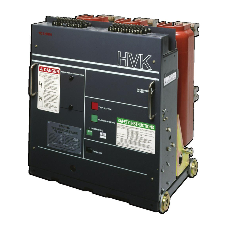
  9. Toshiba VK Series User manual

Toshiba VK Series User manual

Document
:
GF
077601
-
B
TOSHIBA
INSTRUCTIONS
INSTALLATION
-
OPERATION
-
MAINTENANCE
Type
VK
&
HVK
Series
Vacuum
Circuit
Breakers
5
-
15
kV
APPLICABLE
TYPE
FORMS
(
1200
A
)
(
2000
A
)
(
3000
A
)
VK
-
6
M
32
A
HVK
-
6
M
32
A
VK
-
6
M
40
A
HVK
-
6
M
40
A
VK
-
8
M
40
A
HVK
-
8
M
40
A
VK
-
10
M
25
A
2
HVK
-
10
M
25
A
2
VK
-
10
M
40
A
HVK
-
10
M
40
A
VK
-
6
M
50
VK
-
10
M
50
VK
-
6
P
32
A
HVK
-
6
P
32
A
VK
-
6
P
40
A
HVK
-
6
P
40
A
VK
-
8
P
40
A
HVK
-
8
P
40
A
VK
-
10
P
25
A
2
HVK
-
10
P
25
A
2
VK
-
10
P
40
A
HVK
-
10
P
40
A
VK
-
6
P
50
VK
-
10
P
50
VK
-
8
Q
40
VK
-
10
Q
40
VK
-
6
Q
50
VK
-
10
Q
50
NOTES
:
1
)
The
designation
of
H
before
VK
(
ie
.
HVK
)
denotes
that
the
circuit
breaker
unit
was
assembled
in
the
USA
using
domestic
and
foreign
components
.
All
references
to
model
numbers
in
this
manual
will
be
by
the
numbers
following
the
VK
-
and
HVK
-
.
2
)
This
manual
was
written
for
the
Toshiba
type
form
circuit
breakers
listed
on
this
page
used
in
conjunction
with
Toshiba
cells
.
For
circuit
breakers
utilized
in
the
conversion
of
other
equipment
,
a
supplemental
instruction
manual
should
be
obtained
from
the
conversion
manufacturer
.
i
\
Issued
2
/
95
.
Supersedes
GFO
770
O
1
-
A
Dated
12
/
94
.
Courtesy of NationalSwitchgear.com
INTRODUCTION
Page
i
READ
THIS
MANUAL
carefully
for
important
information
about
safety
,
handling
,
installation
,
operation
,
maintenance
,
and
parts
replacements
for
spring
-
operation
-
type
,
VK
and
HVK
series
vacuum
circuit
breakers
.
This
manual
and
all
accompanying
drawings
should
be
considered
a
permanent
part
of
the
equipment
.
They
should
be
readily
available
for
review
and
reference
at
all
times
.
DIMENSIONS
shown
in
the
manual
are
metric
and
/
or
their
U
.
S
.
equivalent
.
INQUIRIES
should
be
addressed
to
:
Field
Service
Department
Toshiba
International
Corporation
13131
West
Little
York
Road
Houston
,
Texas
77041
USA
Telephone
:
(
713
)
466
-
0277
(
800
)
231
-
1412
(
800
)
527
-
1204
(
Canada
)
(
713
)
466
-
8773
Fax
:
Use
only
Toshiba
-
authorized
replacement
parts
.
This
equipment
is
designed
and
built
in
accordance
with
applicable
safety
standards
in
effect
on
the
date
of
manufacture
.
Unauthorized
modifications
will
void
warranty
and
can
result
in
severe
injury
,
death
and
property
damage
.
Do
not
make
any
modifications
to
this
equipment
without
the
written
approval
of
Toshiba
.
®
TOSHIBA
INTERNATIONAL
CORPORATION
,
1995
Courtesy of NationalSwitchgear.com
(
(
(
.
Courtesy of NationalSwitchgear.com
TABLE
OF
CONTENTS
Page
ii
SAFETY
RECEIVING
,
STORAGE
AND
HANDLING
Receiving
and
Unpacking
Acceptance
Inspection
Lifting
for
Handling
and
Moving
Storage
Inspection
During
Storage
GENERAL
DESCRIPTION
Safety
Devices
Interlock
Lever
Self
Coupling
Type
Secondary
(
Control
Circuit
)
Disconnects
INSTALLATION
Service
Conditions
Rating
Lifting
for
Installation
Using
the
Portable
Lifter
Moving
the
Circuit
Breaker
in
the
Cell
PRE
-
ENERGIZATION
CHECK
General
Electrical
Checks
4
4
4
5
6
6
7
8
9
10
11
11
11
13
13
15
18
18
18
19
OPERATION
19
Manual
Operation
Electrical
Operation
Control
Circuit
Operation
Closing
Sequence
Charging
Sequence
Tripping
(
Opening
)
Sequence
Mechanism
Operation
Closing
Charging
Tripping
Trip
Free
20
20
20
20
20
25
25
25
25
25
26
MAINTENANCE
Maintenance
Program
Maintenance
Record
Servicing
Equipment
Inspection
and
Maintenance
Types
.
.
Inspection
and
Maintenance
Intervals
Wipe
Measurement
Vacuum
Check
Troubleshooting
Guidelines
Replacement
of
Parts
Auxiliary
Switch
Closing
Coil
and
Trip
Coil
.
.
.
Control
Circuit
Board
Control
Circuit
Board
Fuse
.
..
26
26
27
28
30
36
37
41
44
45
47
49
51
53
Replacement
Parts
List
CONVERSIONS
WARRANTY
and
LIMITATION
OF
LIABILITY
54
57
Courtesy of NationalSwitchgear.com
f
(
(
Courtesy of NationalSwitchgear.com
Page
1
SAFETY
IMPORTANT
MESSAGES
Read
this
manual
and
follow
its
Instructions
.
Signal
words
such
as
DANGER
,
WARNING
and
CAUTION
will
be
followed
by
important
safety
information
that
must
be
carefully
reviewed
.
Indicates
a
situation
which
will
result
in
death
,
serious
injury
,
and
severe
property
damage
if
you
do
not
follow
instructions
.
A
DANGER
Means
that
you
might
be
seriously
injured
or
killed
if
you
do
not
follow
instructions
.
Severe
property
damage
might
also
occur
.
A
CAUTION
:
Means
that
you
might
be
injured
if
you
do
not
follow
instructions
.
Equipment
damage
might
also
occur
.
NOTE
:
Gives
you
helpful
information
.
(
SAFETY
CODES
Comply
with
ail
applicable
state
and
local
codes
.
Unless
superseded
by
state
and
local
codes
,
adhere
to
all
applicable
ANSI
,
OSHA
,
IEEE
,
NEMA
and
National
Electrical
Code
(
NFPA
70
)
and
Maintenance
Procedures
in
NFPA
70
B
standards
.
This
includes
standards
pertaining
to
the
manufacture
,
assembly
,
installation
,
grounding
,
maintenance
,
conversion
,
rating
and
operation
of
:
1
)
Metal
-
clad
switchgear
2
)
Power
switchgear
3
)
Metal
-
clad
and
station
type
cubicle
switchgear
4
)
AC
high
voltage
circuit
breakers
Courtesy of NationalSwitchgear.com
SAFETY
READ
ALL
SAFETY
SIGNS
Safety
signs
are
placed
on
the
circuit
breaker
for
your
safety
and
instruction
.
A
DANGER
Read
and
follow
the
instructions
in
this
manual
and
on
the
safety
signs
located
on
the
equipment
.
DO
WOT
REMOVE
.
DESTTOT
.
OB
COVB
THB
LUC
.
READ
TtC
INSTRUCTION
MANUAL
CAREMJLY
BERM
!
INSTALLING
.
OPERA
1
MG
.
OR
S
8
MCMG
IMS
EBUMENT
.
Keep
the
safety
sign
visible
and
in
good
shape
.
HAZARDOUS
VOLTAGE
H
•
Trip
On
*
*
Bcmmft
And
Never
remove
,
damage
,
or
cover
any
safety
sign
.
CoiMCtatt
MOVING
PARTS
AND
POWERRJL
SPRINGS
Can
R
«
aaM
k
»
Lots
of
fiogiri
«
r
Unto
•
Oo
Not
Place
YovHinto
or
»
y
Part
of
Your
Body
MdeTMeEqaipmm
Shows
'
CHARGHT
or
wm
•
CLOSED
*
.
ToOiactorgoSprtMc
In
Disconnect
Poaaba
Degrees
TRIP
BUTTON
.
Than
CLOSING
BUTTON
And
TRP
BUTTON
Again
FOR
REPLACEMENT
INSTRUCTION
MANUALS
OR
TECHNICAL
ASSISTANCE
CALL
1
-
000
-
231
-
1412
TOSHIBA
INTERNATIONAL
CORPORATION
SAFETY
INSTRUCTIONS
READ
INSTRUCTION
MANUAL
BEFORE
ATTEMPTING
THE
FOLLOWING
PROCEDURES
MANUAL
OPERATING
PROCEDURE
TO
CHARGE
SPRINGS
:
Remove
Charging
Handle
Socket
Cover
and
Insert
Charging
Handle
Into
Socket
Opening
.
Rachet
Handle
Up
and
Down
Until
A
Click
is
Heard
And
Spring
Indicator
Reads
CHARGED
(
Yellow
)
.
Ratchet
Handle
No
Further
.
Remove
Handle
and
Replace
Socket
Cover
.
Push
the
CLOSING
BUTTON
.
Circuit
Breaker
Indicator
Will
Then
Read
CLOSED
(
Red
)
and
DISCHARGED
(
White
)
.
Push
the
TRIP
BUTTON
.
Circuit
Breaker
Indicator
Wri
Then
Reed
OPEN
(
Green
)
and
DISCHARGED
(
White
)
.
The
Following
Can
Result
In
Equipment
Damage
.
Depression
Of
The
CLOSING
BUTTON
With
The
Circuit
Breaker
CLOSED
.
Depression
Of
The
CLOSING
BUTTON
With
The
INTERLOCK
LEVER
Raised
.
Depression
Of
The
CLOSING
BUTTON
With
The
TRIP
BUTTON
Depressed
.
TO
CLOSE
BREAKER
:
TO
OPEN
BREAKER
:
NOTE
:
INSTALLATION
Or
REMOVAL
*
INDICATORS
Must
Read
DISCHARGED
(
White
)
And
OPEN
(
Green
)
Before
The
Breaker
Can
Be
installed
Into
Or
Removed
From
The
Cell
(
Cradle
)
.
Courtesy of NationalSwitchgear.com
Page
3
SAFETY
QUALIFIED
OPERATORS
ONLY
Only
qualified
persons
are
to
install
,
operate
or
service
this
equipment
according
to
all
applicable
codes
and
established
safety
practices
.
A
qualified
person
must
:
1
)
Carefully
read
the
entire
instruction
manual
.
2
)
Be
skilled
in
the
installation
,
construction
or
operation
of
the
equipment
and
aware
of
the
hazards
involved
.
3
)
Be
trained
and
authorized
to
safely
energize
,
de
-
energize
,
clear
,
ground
,
lockout
and
tag
circuits
in
accordance
with
established
safety
practice
.
4
)
Be
trained
and
authorized
to
perform
the
service
,
maintenance
or
repair
of
this
equipment
.
5
)
Be
trained
in
the
proper
care
and
use
of
protective
equipment
such
as
rubber
gloves
,
hard
hat
,
safety
glasses
,
face
shield
,
flash
clothing
,
etc
.
in
accordance
with
established
practices
.
6
)
Be
trained
in
rendering
first
aid
.
Courtesy of NationalSwitchgear.com
RECEIVING
,
HANDLING
AND
STORAGE
Page
4
RECEIVING
AND
UNPACKING
The
circuit
breaker
units
are
subjected
to
factory
production
testing
prior
to
being
packed
and
shipped
.
ACCEPTANCE
INSPECTION
Confirm
that
the
circuit
breaker
unit
is
complete
,
correct
as
specified
and
undamaged
from
shipment
and
handling
.
Upon
receipt
of
the
equipment
,
do
the
following
:
1
)
Make
an
immediate
inspection
for
damage
which
might
have
occurred
during
shipment
(
Fig
.
1
)
.
If
damage
is
discovered
,
it
should
be
noted
with
the
carrier
prior
to
accepting
the
shipment
,
if
possible
.
Fig
.
1
Inspect
for
Damage
2
)
Carefully
unpack
the
equipment
sufficiently
to
check
for
missing
parts
or
concealed
damage
.
3
)
Keep
the
equipment
upright
(
Fig
.
2
)
.
/
A
CAUTION
:
Never
lay
the
equipment
on
its
side
or
upside
down
,
equipment
damage
to
occur
.
This
may
cause
4
)
File
a
claim
with
the
carrier
for
any
damaged
or
missing
items
and
immediately
notify
the
nearest
Toshiba
International
Corporation
representative
.
Do
not
install
or
energize
equipment
that
has
been
damaged
.
Damaged
equipment
can
fail
during
operation
,
resulting
in
fire
and
explosion
.
Fig
.
2
The
Circuit
Breaker
should
be
kept
Upright
5
)
If
the
circuit
breaker
has
been
utilized
for
the
conversion
of
other
equipment
,
seethe
CONVERSIONS
Section
of
this
manual
.
Confirm
that
your
conversion
manufacturer
is
in
compliance
with
this
section
.
f
Courtesy of NationalSwitchgear.com
RECEIVING
,
HANDLING
AND
STORAGE
Page
5
LIFTING
FOR
HANDLING
AND
MOVING
When
handling
and
moving
the
circuit
breaker
,
the
suspension
techniques
shown
in
this
section
may
be
used
.
When
installing
or
removing
the
circuit
breaker
from
the
cell
above
floor
level
,
refer
to
the
"
Lifting
For
Installation
"
instructions
in
the
INSTALLATION
Section
of
this
manual
.
Do
not
attempt
installation
of
the
circuit
breaker
above
floor
level
using
the
lifting
methods
described
in
this
section
.
Always
use
a
Toshiba
Portable
Lifter
for
installation
.
Care
and
caution
should
be
used
when
handling
the
circuit
breaker
units
to
avoid
damage
to
the
equipment
and
personal
injury
.
Fig
.
3
Lifting
the
Circuit
Breaker
with
Lifting
Hooks
.
Always
keep
the
circuit
breaker
in
a
generally
upright
position
.
A
CAUTION
:
When
lifting
,
the
circuit
breaker
will
tilt
slightly
backwards
.
Stand
clear
of
the
breaker
when
lifting
or
you
may
be
injured
.
Always
use
lifting
equipment
suitable
for
handling
the
weight
of
the
unit
.
The
capability
of
the
lifting
equipment
to
handle
the
size
and
weight
of
the
circuit
breaker
should
be
confirmed
prior
to
lifting
.
A
CAUTION
:
Attempting
to
manually
lift
the
circuit
breaker
can
cause
serious
injury
or
equipment
damage
.
Always
use
suitable
lifting
equipment
.
Fig
.
4
Circuit
Breaker
Tilting
Backward
while
Lifting
.
WHEN
LIFTING
:
6
M
32
A
6
P
32
A
6
M
40
A
6
P
40
A
8
M
40
A
8
P
40
A
10
M
25
A
2
10
P
25
A
2
10
M
40
A
10
P
40
A
i
Lift
the
circuit
breaker
as
shown
in
Fig
.
3
and
Fig
.
4
.
Courtesy of NationalSwitchgear.com
RECEIVING
,
HANDLING
AND
STORAGE
Page
6
WHEN
LIFTING
:
6
M
50
6
P
50
6
Q
50
8
Q
40
10
Q
40
10
M
50
10
P
50
10
Q
50
Lift
the
circuit
breaker
as
shown
in
Fig
.
5
.
The
circuit
breaker
has
a
set
of
lifting
plates
as
accessories
.
Lifting
plates
must
be
removed
before
attempting
to
install
into
cell
.
NOTE
:
WHEN
LIFTING
FOR
INSTALLATION
:
The
VK
&
HVK
Circuit
Breaker
Types
listed
in
this
manual
use
the
procedure
described
in
the
INSTALLATION
section
.
Fig
.
S
Lifting
Circuit
Breaker
with
Lifting
Plates
.
STORAGE
If
the
circuit
breaker
is
to
be
stored
for
any
length
of
time
prior
to
installation
,
the
following
precautions
should
be
taken
:
1
)
The
original
packing
should
be
restored
,
if
possible
.
2
)
Do
not
subject
the
equipment
to
moisture
or
sun
rays
.
Store
in
cool
,
clean
,
and
dry
location
.
3
)
Place
a
dust
cover
over
the
circuit
breaker
packaging
to
protect
against
dirt
and
moisture
.
4
)
Store
in
an
upright
position
.
INSPECTION
DURING
STORAGE
Routine
scheduled
inspection
is
necessary
if
storage
is
for
an
extended
period
.
The
unit
should
be
checked
for
condensation
,
moisture
,
corrosion
,
and
vermin
.
Prior
to
installation
,
the
circuit
breaker
should
be
carefully
examined
for
evidence
of
physical
damage
,
corrosion
,
or
other
deterioration
.
Refer
to
the
PRE
-
ENERGIZATION
section
of
this
manual
.
The
MAINTENANCE
section
of
this
manual
describes
various
types
of
inspections
recommended
for
this
circuit
breaker
during
the
operation
period
.
Fig
.
6
Circuit
Breaker
Storage
Courtesy of NationalSwitchgear.com
Page
7
GENERAL
DESCRIPTION
The
Toshiba
VK
&
HVK
Series
medium
voltage
circuit
breakers
in
this
manual
are
designed
for
applications
at
utilization
voltages
ranging
from
5
kV
to
15
kV
and
interrupting
ratings
ranging
from
250
MVA
to
1000
MVA
.
The
circuit
breakers
are
intended
for
use
only
in
metal
-
clad
distribution
switchgear
and
other
limited
applications
.
Fig
.
7
,
Fig
.
8
,
and
Fig
.
9
illustrate
and
identify
various
components
of
the
circuit
breaker
.
COMPONENTS
LEGEND
:
Handle
for
moving
circuit
breaker
Secondary
disconnects
Rating
interlock
pin
6
M
/
P
/
Q
50
8
Q
40
10
Q
40
10
M
/
P
/
Q
50
Interlock
lever
Wheel
Primary
disconnects
Barrier
Racking
screw
Vacuum
interrupter
Flexible
conductor
Insulated
operation
rod
Rating
interlock
plate
6
M
/
P
32
A
6
M
/
P
40
A
10
M
/
P
25
A
2
10
M
/
P
40
A
8
M
/
P
40
A
1
)
Fig
.
7
Front
View
2
)
3
)
4
)
5
)
6
)
7
)
8
)
9
)
10
)
11
)
12
)
Fig
.
8
Side
View
Use
only
genuine
Toshiba
replacement
parts
and
accessories
.
Improper
components
could
cause
the
circuit
breaker
to
malfunction
.
i
Fig
.
9
Rear
View
Courtesy of NationalSwitchgear.com
Page
8
GENERAL
DESCRIPTION
SAFETY
DEVICES
Safety
interlocks
and
guards
are
provided
as
an
integral
part
of
the
equipment
design
.
These
devices
are
provided
for
your
safety
.
A
DANGER
Never
Defeat
,
Modify
or
Bypass
any
Safety
Devices
,
interlocks
,
or
operating
mechanism
.
This
would
make
the
equipment
unsafe
.
Fire
,
explosion
,
severe
injury
,
death
,
and
property
damage
could
occur
.
Do
not
operate
this
equipment
unless
all
covers
and
panels
are
in
place
.
A
.
SPRING
CHARGE
INTERLOCK
With
the
closing
springs
charged
,
the
circuit
breaker
cannot
be
moved
into
or
out
of
the
cell
.
A
steel
plunger
{
Fig
.
10
)
mechanically
prevents
the
breaker
unit
from
being
withdrawn
until
the
closing
springs
are
completely
discharged
.
B
.
CLOSE
PIN
INTERLOCK
With
the
circuit
breaker
closed
,
it
cannot
be
moved
between
the
connected
,
test
and
disconnected
positions
.
Also
,
it
cannot
be
moved
into
or
out
of
the
cubicle
.
The
close
pin
interlock
(
Fig
.
11
)
is
mechanically
held
down
,
thus
locking
the
unit
in
place
.
Additionally
,
a
safety
plate
blocks
the
racking
handle
opening
to
prevent
insertion
of
the
handle
.
Fig
.
11
Typical
Close
Pin
Interlock
C
.
RATING
INTERLOCK
PIN
/
PLATE
The
circuit
breaker
has
an
interlock
to
prevent
the
breaker
from
connecting
to
a
cell
that
has
a
continuous
current
rating
different
from
the
circuit
breaker
.
This
interlock
is
accomplished
by
the
rating
interlock
pin
{
Fig
.
12
)
on
the
6
M
/
P
/
Q
50
,
8
Q
40
,
10
Q
40
,
and
10
M
/
P
/
Q
5
O
.
Courtesy of NationalSwitchgear.com
GENERAL
DESCRIPTION
Page
9
The
interlock
is
accomplished
by
a
rating
interlock
plate
(
Fig
.
13
)
on
the
6
M
/
P
32
A
,
6
M
/
P
40
A
,
10
M
/
P
25
A
2
,
8
M
/
P
40
A
and
10
M
/
P
40
A
.
Fig
.
13
Rating
Interlock
Plate
INTERLOCK
LEVER
The
interlock
lever
(
Fig
.
14
)
on
the
right
side
of
the
circuit
breaker
front
panel
cannot
be
lifted
when
the
circuit
breaker
is
closed
.
Before
lifting
the
interlock
lever
,
verify
that
the
open
-
closed
indicator
reads
"
OPEN
"
(
green
)
.
When
the
interlock
lever
is
lifted
,
the
closing
action
is
blocked
both
electrically
and
mechanically
.
With
the
interlock
lever
up
,
the
microswitch
(
Fig
.
15
)
is
open
,
thus
electrically
preventing
the
circuit
breaker
from
being
closed
.
.
i
Fig
.
15
Interlock
Lever
Microswitch
Courtesy of NationalSwitchgear.com
Page
10
GENERAL
DESCRIPTION
SELF
COUPLING
TYPE
SECONDARY
(
CONTROL
CIRCUIT
)
DISCONNECTS
Self
coupling
type
secondary
(
Control
Circuit
)
disconnects
are
mounted
on
the
top
of
the
circuit
breaker
(
Fig
.
16
)
.
The
control
circuit
is
connected
to
the
appropriate
stationary
contacts
(
Fig
.
17
)
when
the
circuit
breaker
is
in
the
connected
or
test
position
.
Hazardous
Voltage
.
Turn
Off
and
Lock
Out
Primary
and
Control
Circuit
Power
Before
Servicing
.
To
ensure
smooth
connection
of
the
self
coupling
contacts
,
apply
a
thin
film
of
TOSHIBA
B
8
grease
to
the
stationary
contacts
before
inserting
the
circuit
breaker
into
the
cell
(
cradle
)
.
Fig
.
16
Secondary
Disconnects
Do
not
allow
grease
or
any
other
substances
to
contaminate
insulating
materials
.
Contaminated
insulators
can
allow
a
short
circuit
or
ground
fault
to
occur
.
Fig
.
17
Secondary
Disconnects
Courtesy of NationalSwitchgear.com
INSTALLATION
Page
11
SERVICE
CONDITIONS
Do
not
install
this
equipment
in
areas
where
unusual
service
conditions
exist
.
Using
this
equipment
in
other
than
usual
service
conditions
can
result
in
equipment
failure
.
Toshiba
VK
&
HVK
Series
Circuit
Breakers
are
intended
for
use
in
usual
service
conditions
as
defined
by
ANSI
.
The
temperature
of
the
air
(
ambient
air
temperature
)
surrounding
the
switchgear
should
be
between
the
limits
of
-
30
°
C
(
-
22
°
F
)
and
+
40
°
C
(
104
°
F
)
.
The
altitude
of
the
equipment
installation
should
not
exceed
3300
ft
(
1000
m
)
.
Temperature
,
altitude
or
other
conditions
outside
of
the
usual
limits
may
require
derating
or
other
special
equipment
.
Contact
Toshiba
International
Corporation
for
additional
information
.
NOTE
:
RATING
Prior
to
Installation
:
The
maximum
fault
current
capacity
of
the
power
system
at
the
point
of
installation
should
be
verified
.
This
value
must
not
exceed
the
symmetrical
interrupting
capability
of
the
circuit
breaker
.
Fig
.
18
illustrates
a
typical
circuit
breaker
nameplate
and
ratings
.
-
*
-
y
’
Spttcp
«
i
.
_
,
s
.
'
usrrccwfailil
r
;
BREAKER
<
*
*
m
.
m
•
.
ypc
•
V
.
-
::
VEYtL
-
^
•
•
-
w
:
•
Cfafl
—
SHOUT
-
cneurrAMFs
.
&
A
DANGER
Do
not
exceed
the
ratings
specified
on
the
circuit
breaker
nameplate
or
system
accessories
.
Underrated
equipment
can
fail
during
operation
causing
fire
,
explosion
,
severe
injury
,
death
,
and
property
damage
.
m
-
i
-
rfcVT
..
vlio
~
•
;
;
>
;
-
'
Mi
<
v
,
-
5
:
^
W
*
TPy
>
TH
'
v
1
*
*
'
:
-
v
,
T
*
V
*
’
y
.
:
MM
.
*
>
Fig
.
18
Typical
Circuit
Breaker
Nameplate
To
calculate
the
required
Symmetrical
Interrupting
Capability
,
use
the
formula
in
Note
4
and
5
of
Table
1
.
All
system
accessories
such
as
surge
suppressors
,
lightning
arrestors
,
etc
.
should
be
checked
to
verify
their
ratings
capacity
.
Courtesy of NationalSwitchgear.com
Page
12
INSTALLATION
Table
1
.
RATINGS
(
Symmetrical
Rating
Basis
,
ANSI
C
37.06
)
Rotated
Required
Capabilities
Identification
Rated
Values
+
Current
Value
#
Voltage
kmdation
Current
Type
Form
of
Breaker
Level
iif
3
-
pheM
rm
»
Vmax
Rated
Maximum
rma
3
H
sa
Hp
’
Cfadng
Voltage
Class
Rated
Rated
Voltage
Range
Factor
Con
-
tinous
SCA
end
(
MVA
)
Rated
Withstand
Test
Voltage
Short
droit
Latching
CapeWIty
(
kV
)
Rated
kiter
Rated
rma
Pw
-
Vafcoq
*
Divided
Voltage
mm
Ciaront
Rating
nrw
rapthg
(
kV
)
K
Current
Rating
Timor
Rated
dra
*
*
£
i
Trippmg
Ddey
,
Y
(
Seconds
)
Time
(
2
f
13
)
*
at
m
(
Cydeo
)
60
Hz
(
at
Low
(
A
)
Frequency
Crest
Max
.
vine
Impcdse
Voltage
rma
k
V
)
Ctmnt
Voltage
(
kA
)
IkA
)
!
(
kV
)
(
kV
)
(
4
)
*
6
M
32
A
6
P
32
A
4.10
4.76
1.24
60
250
19
1200
2000
3
2
29
3.85
36
36
58
4.16
4.70
1.24
60
250
19
3
2
28
3.85
30
36
58
6
M
40
A
(
1
)
*
0
P
4
OA
(
if
4.10
350
4.70
1.0
19
00
1200
2000
41
3
2
4.70
41
41
00
4.10
4.70
1.0
60
350
19
3
2
41
4.70
41
41
60
0
M
5
O
0
P
6
O
6
Q
50
4.16
350
4.76
19
1200
2000
3000
1.19
60
41
3
2
4.0
49
49
78
350
4.70
4.70
4.18
4.10
1.19
00
3
19
41
2
4.0
49 49
78
1.19
60
350
19
41
3
4.0
2
49
49
78
8
M
40
A
6
P
40
A
BQ
40
(
if
500
8.25
7.2
1.25
95
1200
2000
3000
3
36
33
2
0.0
41
41
00
7.2
8.25
1.25
500
36
95
33
3
0.6
2
41 41
60
7.2
8.25
1.25
500
36
3
95
33
0.6
2
41 41
66
10
M
25
A
2
10
P
25
A
2
500
13.0
15
1.30
95
1200
2000
18
36
3
2
11.5
23 23
37
13.8
500
1.30
36
15
95
18
3
2
11.5
23 23
37
10
M
40
A
10
P
40
A
10
Q
4
O
(
if
750
13.8
15
1.30
36
95
1200
2000
3000
28
3
2
11.5
36
36
58
t
750
13.8
15
1.30
36
95
28
3
2
11.5
36
50
30
13.8
15
95
750
1.30
36
28
2
11.5
3
36 36
58
10
P
40
AO
)
*
10
Q
40
(
if
1000
1000
2000
3000
13.8
15
1.0
95
37
36
3
2
37
15
37
59
13.8
15
95
1.0
36
3
37
2
15
37
37
59
10
M
50
10
P
50
10
Q
50
13.8
1000
1000
1000
1.30
15
30
95
1200
2000
3000
37
3
11.5
46
2
48
77
13.0
15
1.30
36
95
37
3
2
48
11.5
48
77
13.8
15
1.30
30
95
37
3
2
11.5
48 48
77
*
Numbers
in
parenthesis
refer
to
the
NOTES
,
below
.
NOTES
:
1
)
ANSI
C
37.06
does
not
define
these
ratings
.
2
)
Maximum
voltage
for
which
the
circuit
breaker
is
designed
and
the
upper
limit
for
operation
.
3
)
K
is
the
ratio
of
rated
maximum
voltage
to
the
lower
limit
of
the
range
of
operating
voltage
in
which
the
required
symmetrical
and
asymmetrical
interrupting
capabilities
vary
in
inverse
proportion
to
the
operating
voltage
.
4
)
To
obtain
the
required
symmetrical
interrupting
capability
of
circuit
breaker
at
an
operating
voltage
between
1
/
K
times
rated
maximum
voltage
and
rated
maximum
voltage
,
the
following
formula
shall
be
used
:
Required
Symmetrical
Interrupting
(
Vmax
)
(
Vop
)
Capability
=
(
SCA
)
X
Where
:
SCA
=
Short
-
Circuit
rms
Current
Rating
from
Table
(
kA
)
Vmax
=
Rated
Maximum
rms
Voltage
(
kV
)
from
Table
Vop
=
Measured
operating
voltage
(
kV
)
5
)
Current
values
in
this
column
are
not
to
be
exceeded
even
for
operating
voltages
below
1
/
K
times
rated
maximum
voltage
.
For
voltages
between
the
rated
maximum
voltage
and
1
/
K
times
rated
maximum
voltage
,
follow
(
4
)
above
.
/
[
Courtesy of NationalSwitchgear.com
Page
13
INSTALLATION
LIFTING
FOR
INSTALLATION
Unlike
the
lifting
procedures
recommended
in
the
RECEIVING
,
STORAGE
AND
HANDLING
section
.
Lifting
for
Installation
purposes
requires
a
different
technique
.
A
Portable
lifter
as
shown
in
Fig
.
19
should
be
used
for
the
insertion
or
removal
of
a
circuit
breaker
to
the
switchgear
compartment
above
floor
level
.
The
portable
lifter
may
also
be
used
to
transport
the
circuit
breaker
to
and
from
the
switchgear
.
AWARNING
Do
not
attempt
to
install
or
remove
a
circuit
breaker
above
floor
level
from
a
compartment
by
using
the
lifting
eyes
or
plates
.
Use
a
Toshiba
portable
lifter
.
F
'
\
\
'
Discharge
springs
completely
before
installation
.
!
A
CAUTION
:
Always
insure
the
portable
lifter
is
operated
on
a
firm
and
level
surface
.
USING
THE
PORTABLE
LIFTER
1
)
Set
wheel
stops
to
the
locked
position
.
2
)
Place
the
circuit
breaker
on
the
lifter
bucket
and
lock
in
place
with
the
interlock
pin
{
Fig
.
20
)
.
nv
/
mm
Do
not
transport
the
circuit
breaker
without
the
interlock
pin
locked
in
place
.
Portable
Lifter
Interlock
Pm
in
Place
Courtesy of NationalSwitchgear.com
Page
14
INSTALLATION
FiWZ
^
mmd
Do
not
transport
the
Vacuum
Circuit
Breaker
in
the
elevated
position
while
using
portable
lifter
.
3
)
Unlock
the
wheel
stops
and
move
the
lifter
into
position
in
front
of
the
cell
.
4
)
Before
moving
the
circuit
breaker
on
or
off
the
lifter
bucket
,
make
sure
that
:
a
)
The
bucket
tab
is
lowered
over
the
cell
stud
to
insure
the
lifter
does
not
move
(
Fig
.
21
)
.
b
)
The
wheel
stops
are
again
locked
.
The
portable
lifter
must
be
securely
fixed
to
the
circuit
breaker
cell
before
transferring
the
circuit
breaker
to
or
from
the
cell
.
5
)
Remove
the
circuit
breaker
interlock
pin
.
6
)
Follow
the
procedure
"
MOVING
THE
CIRCUIT
BREAKER
IN
THE
CELL
"
for
insertion
into
the
equipment
cell
.
MOUNTING
PADS
Some
installations
utilize
elevated
equipment
mounting
pads
.
This
type
of
installation
will
increase
the
overall
height
of
the
equipment
.
Pads
should
not
increase
the
equipment
height
more
than
6
inches
,
or
the
portable
lifter
may
not
work
.
Additionally
,
mounting
pads
should
extend
no
more
than
6
inches
forward
of
the
switchgear
.
<
Courtesy of NationalSwitchgear.com
Page
15
INSTALLATION
MOVING
THE
CIRCUIT
BREAKER
IN
THE
CELL
A
DANGER
Fire
and
explosion
hazard
.
Trip
circuit
breaker
open
and
discharge
springs
before
attempting
removal
or
Installation
.
Unit
contains
powerful
springs
.
Discharge
springs
completely
before
servicing
.
To
Discharge
Springs
:
In
either
Disconnect
or
out
of
cell
position
.
Depress
Trip
Button
,
then
Closing
Button
,
and
Trip
Button
again
(
Fig
.
22
)
.
Circuit
Breaker
with
Springs
Discharged
Fig
.
22
Disconnect
Position
-
The
circuit
breaker
is
first
placed
into
this
position
when
installed
into
the
cell
(
Fig
.
23
)
.
1
)
With
the
closing
spring
charged
,
the
circuit
breaker
cannot
be
moved
into
or
out
of
the
cell
.
NOTE
:
2
)
With
the
circuit
breaker
closed
,
it
cannot
be
moved
between
the
Connected
,
Test
and
Disconnect
Positions
and
it
cannot
be
moved
into
or
out
of
the
cell
.
Test
Position
-
This
position
is
between
the
Disconnected
Position
and
the
Connected
Position
(
Fig
.
24
)
.
Fig
.
23
Circuit
Breaker
at
Disconnected
Position
To
Move
the
Circuit
Breaker
from
the
Disconnect
Position
to
Test
Position
:
1
)
Lift
and
hold
the
interlock
lever
on
the
right
side
as
shown
in
Fig
.
25
.
2
)
Hold
both
grip
handles
(
Fig
.
26
)
and
push
the
circuit
breaker
into
the
cell
.
When
the
interlock
lever
is
released
at
the
predetermined
position
,
make
sure
that
the
interlock
lever
has
dropped
completely
.
NOTE
:
Courtesy of NationalSwitchgear.com

Other manuals for VK Series

1

This manual suits for next models

29

Other Toshiba Circuit Breaker manuals

Toshiba EAS630G User manual

Toshiba

Toshiba EAS630G User manual

Toshiba VK Series User manual

Toshiba

Toshiba VK Series User manual

Toshiba HV6FS User manual

Toshiba

Toshiba HV6FS User manual

Toshiba HV6FS-MLD User manual

Toshiba

Toshiba HV6FS-MLD User manual

Toshiba XVFN10 User manual

Toshiba

Toshiba XVFN10 User manual

Popular Circuit Breaker manuals by other brands

Eaton NHI-E PKZ0 Series installation instructions

Eaton

Eaton NHI-E PKZ0 Series installation instructions

Siemens 3VT9300-8CB30 operating instructions

Siemens

Siemens 3VT9300-8CB30 operating instructions

Delixi NAVIGATOR Series user manual

Delixi

Delixi NAVIGATOR Series user manual

TERASAKI TemBreak 2 E125 instruction manual

TERASAKI

TERASAKI TemBreak 2 E125 instruction manual

ABB VM1 instruction manual

ABB

ABB VM1 instruction manual

WEG ACW400 manual

WEG

WEG ACW400 manual

Westinghouse DB-75 instructions

Westinghouse

Westinghouse DB-75 instructions

Hyundai HVF Series instruction manual

Hyundai

Hyundai HVF Series instruction manual

ABB SMISSLINE TP 2CCC451032M0109 quick start guide

ABB

ABB SMISSLINE TP 2CCC451032M0109 quick start guide

Allen-Bradley 140G-J-EOP manual

Allen-Bradley

Allen-Bradley 140G-J-EOP manual

Schrack MC1-XD installation instructions

Schrack

Schrack MC1-XD installation instructions

Siemens 3RV1.2 operating instructions

Siemens

Siemens 3RV1.2 operating instructions

Eaton XNH1-A Series Instruction leaflet

Eaton

Eaton XNH1-A Series Instruction leaflet

Siemens Sentron 8UD1721-0AB Series operating instructions

Siemens

Siemens Sentron 8UD1721-0AB Series operating instructions

Eaton ZB-XPLH Instruction leaflet

Eaton

Eaton ZB-XPLH Instruction leaflet

Projoy Electric PEBS-S Instructions for installation and operation

Projoy Electric

Projoy Electric PEBS-S Instructions for installation and operation

Siemens 3WN6 operating instructions

Siemens

Siemens 3WN6 operating instructions

ABB Ekip UP Series Getting started

ABB

ABB Ekip UP Series Getting started

manuals.online logo
manuals.online logoBrands
  • About & Mission
  • Contact us
  • Privacy Policy
  • Terms and Conditions

Copyright 2025 Manuals.Online. All Rights Reserved.