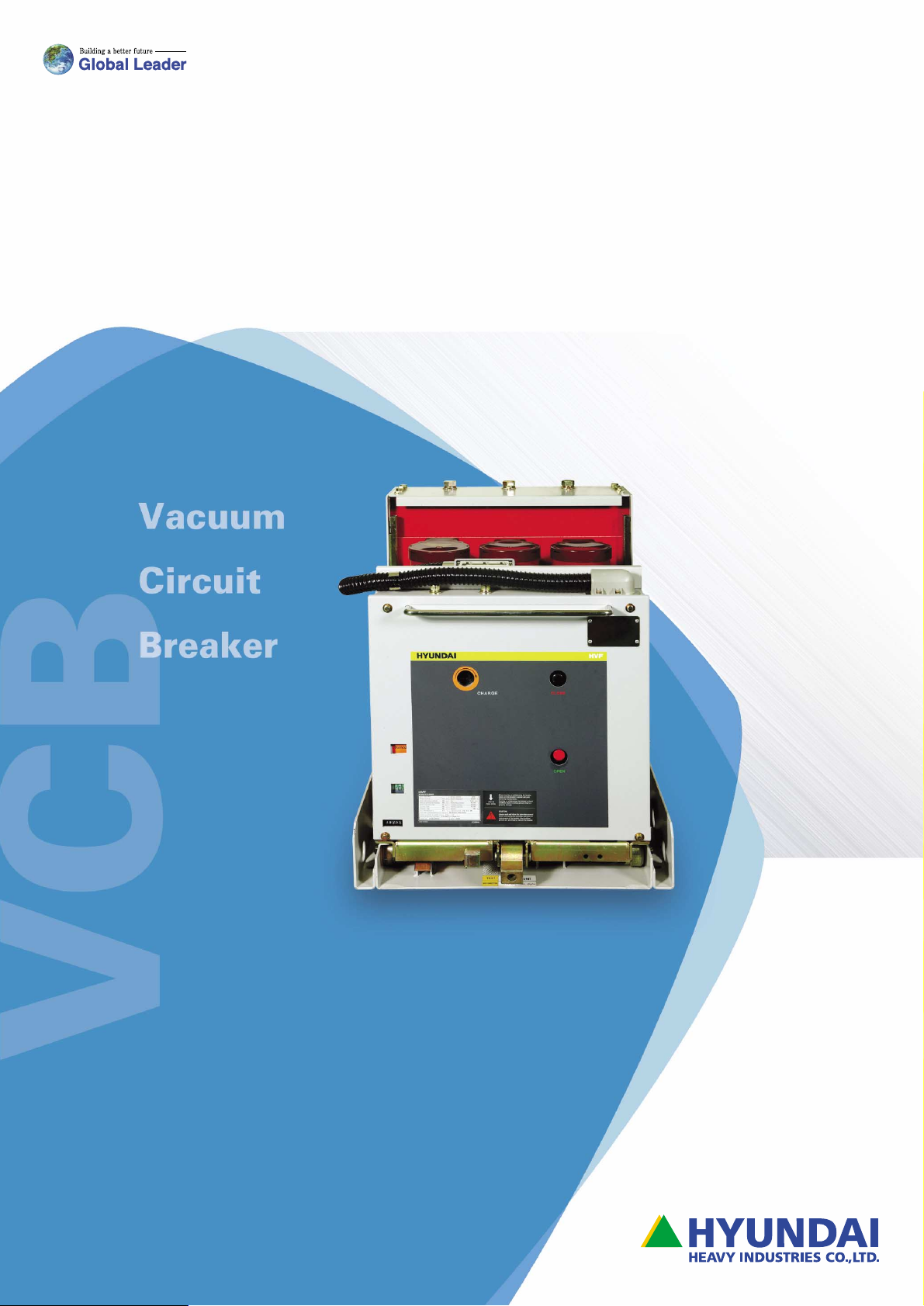
Hyundai HVF Series User manual

Notice
�Read and understand these instructions before attempting any
unpacking, assembly, operation or maintenance of the circuit
breaker.
�This instruction manual should be applied only to HVF/HAF
Series acuum circuit breakers.
�This instruction booklet does not include all items regarding
installation and maintenance procedures.
�For more information, please contact HYUNDAI Hea y Industries
Co,. Ltd. or one of our partners.
�
당사 진공차단기를 사용하시기 전에 반드시 취급설명서를 상세히
읽으신 후 설치 및 운전하십시오.
�
본 취급설명서는 HVF/HAF 시리즈 고압 진공차단기에만 적용됩니다.
�
본 취급설명서에는 설치 및 유지∙보수에 관련된 모든 절차가 포함되어
있지는 않으므로 제품에 대해 더 많은 정보를 필요로 하시는 경우에는
당사로 연락하시기 바랍니다.
�
기술적인 문의 및 A/S사항은 가까운 지사 혹은 뒷 표지의 본사 설계 또는
A/S 담당자에게 문의 바랍니다.
HVF
HAF Series
진공차단기
취급설명서
Vacuum Circuit Breakerl
Instruction Manual

2<< Vacuum Circuit Breaker Instruction Manual
Safety Practices
안전 조항
Safety Practices
This instruction manual applies only to HVF Series vacuum
circuit breakers regarding installation and maintenance
procedures.
Installing and maintaining these products improperly may
result in serious personal injury, property damage, or even
death. Therefore this instruction manual must be read and
understood at any step in unpacking, assembly, operation,
and maintenance of the breaker.
Only qualified persons who are familiar with installing and
maintaining circuit breakers are permitted to work on
breakers, and this instruction manual should be accessible
to those persons at any time.
Signal Words
Signal words used in this instruction manual are divided by
DANGER, WARNING and CAUTION depending on the
situation.
Indicates an imminently hazardous point which, if ignored,
will result in death or serious injury.
This is the most dangerous point.
Indicates a potentially hazardous point which, if ignored,
could result in death or serious injury.
Indicates a potentially hazardous point which, if ignored,
may result in minor or moderate injury. This signal also
warns operators not to work unsafely.
Safety Practices During Moving
안전 조항
기호 설명
이동시 주의사항
When the breaker need to be moved
on flat area, grab the handle and
move the breaker.
When the breaker is lifted by the rope,
it can lean to the terminal side.
Make sure of not making any damage
on person and products.

>> 3
VCB |HVF/HAF Series
Safety Practices During Installation
Safety Practices During Operation
Safety Practices During Maintenance
설치(취부, 접속)시의 주의사항
동작시 주의사항
유지
보수시 주의사항
�Do not work on the breaker unless the
primary circuits are disconnected.
�When connecting bus-bars, tighten
bolts using our standards.
�The product should be installed and
tighened on the plate area.
�Do not install the breaker in areas with
high temperature, high humidity, dust,
corrosive or vibrating conditions.
�Concrete dust or any other dust
should not be inside of the product
when it installed. It can cause fire or
misoperation.
�Connet the control jack tight,
otherwise it can cause the
misoperation.
�Do not touch the main and control
circuit while the productis in operation.
The hazardous voltage can cause
serious problem.
�Do not let the product stay in the
DISCONNECTION position with UNLOCK
state.
�When the heavy product fall down on
the gound, it can cause the serious
accident or product damage.
�Before doing any maintenance, always
open the breaker and make sure that
the main and control circuits are not
charged.
The voltage can be hazardous.
�Discharge the springs and open the
breakers before performing any
breaker maintenance, inspection or
repair. Charged closing or tripping
spring can cause serious injury.
�Use the standard pressure torque to
tighten the bolts. Loosening the bolts
can cause fire.

4<< Vacuum Circuit Breaker Instruction Manual
Safety Practices 2
1. Production Scope 5
2. Technical Data 6
2.1 Service Condition
2.2 Motor Drive
2.3 Multiple Auto-Reclosing
2.4 Interlock Mechanism of the Draw-Out Type Breaker
2.5 Closing (Y9) and Anti-Pumping (K1)
2.6 Open Solenoid (Y1)
2.7 Auxiliary Switch (S1)
2.8 Condenser Trip Device
2.9 Under Voltage Release (Y7)
2.10 2nd Open Solenoid (Y2)
2.11 Cutout Switch
2.12 “Closing Spring Charge” Signal
3. Handling and Installing the Breaker 11
3.1 Unloading and Storage
3.2 Unpacking
3.3 Inspection After Unpacking
3.4 Installation
3.5 Inspection Before Operation
3.6 Manual Operation
4. Structure and Operation 13
4.1 Component List of HAF
4.2 Component List of HVF
4.3 Operation Mode
4.4 Draw In & Out Operation of HAF VCB
4.5 Draw In & Out Operation of HVF VCB
Reference: Draw in & out operation with worm
gear type of mechanism
5. Maintenance and Inspection 21
5.1 Visual Inspection
5.2 Periodical Inspection
5.3 Contact Erosion Limit
5.4 Troubleshooting Guide
5.5 Lubrication
Appendix A 25
Appendix B 26
Maintenance Recording 27
Memo
안전 조항
1. 제작 사양
2. 기술적 데이터
3. 취급설명
4. 구조 및 동작
5. 보수�점검
부록 A
부록 B
보수 점검
Contents
목차

HVF Type (HVF ����1))
HAF Type (HAF ����-�1))
1) Type No. Suffix in the “” and “-”shall
be listed as shown in the column of rated current.
2) Impulse withstand voltage “( )” is avaliable on request.
>> 5
VCB |HVF/HAF Series
Product Scope
제작 사양
01
630
(600)
1250
(1200) 2000 2500 3150
(3000)
7.2
12
24
38
25
20
28 75 2041
2051
6011
6041
2042
2052
2062
2072
6012
6042 6044
6054
6064
7054
6056
6067
7057
ANSI C37
6052
6062
7052
7062
2044
2054
2064 2067
2074 2077
60
1041
1051
1042
1052
1062
1044
1054
1064
2056
1067
IEC60056
31.5
40
25
31.5
28
(36)2)
50 125
75
(95)2)
40
50
12.5
25
31.5
40
80
50 125
31.5
40
80 150(170)2)
150
630
(600)
1250
(1200) 2000 2500 3150
(3000)
50
25
31.5
40
50
25
31.5
40
50
25
31.5
40
12.5
16
20
25
19
20
28
36
50
60
60
75
95
125
1041-4
1051-4
1541-4
1751-4
2341-4
2351-4
6111-4
6121-4
6131-4
6141-4
1072-3
1042-4
1052-4
1162-3
1172-3
1542-4
1752-4
1762-3
1772-3
2342-4
2352-4
2362-3
6112-4
6122-4
6132-4
6142-4 6144-4
6134-4
6146-4
1074-3
1044-4
1054-4
1164-3
1544-4
1754-4
1764-3
2344-4
2354-4
2364-4
1056-4
1166-3
1176-3
1756-4
1766-3
1776-3
2356-4
2366-4
1767-3
1777-3
2367-3
1077-3
1167-3
1177-3
ANSI C37
IEC60056
IEC60056
ESB150
IEC60056
IEC60056
IEC60056
ANSI C37
IEC60056
IEC60056
ESB150
4.76
7.2
12
15
24
(25.8)

2.1 사용 조건
°
2.2 모터 동작
Technical Data
기술적 데이터
02
6<< Vacuum Circuit Breaker Instruction Manual
2.1 Service Condition
1) Ambient Temperature: MAX 40 / MIN -25°
2) Relative Humidity: Less than 95%
3) Site Altitude: Less than 1000 m
2.2 Motor Drive
HVF & HAF VCB have motor-spring type stored-energy
operating mechanism. The closing operation can be done
only after the closing spring is charged.
Consumption during the operation is shown in Table 2-2,
and the inrush current may be disregarded since it lasts for
only a brief period.
The closing spring is fully tensioned by motor (M1) with the
rated voltage applied through terminal no.1&2 of standard
control circuit. Then the limit switch (S21, S22) stop the
motor, and the spring indicator shows "SPRING CHARGED"
by link activation as shown in Fig. 2-1. The charged VCB
can carry out the open-close-open sequential operation
and also the next close-open operation without delay.
Consideration of site altitude!!!
If the site altitude is higher than 1000 m, dielectric
strength of the breaker will be reduced according to
the altitude. Therefore, the values of power frequency
withstand voltage and lightning impulse withstand
voltage should be selected as following.
Rated withstand voltage according to rated voltage
X k(k: Refer to Table 2-1.)
For higher humidity, it is required to use a heater in the
switchgear to prevent dewdrops on the insulation
material and the consecutive decrease in dielectric strength.
1000 m 1500 m 2000 m 2500 m 3000 m
1.0 1.05 1.1 1.15 1.2
24 DC
48 DC
60 DC
110 DC
220 DC
110 AC
220 AC
25.6
53
66
121
242
121
242
20
41
51
93.5
187
93.5
187
500
500
500
500
500
-
-
-
-
-
-
-
700
700
21
10.5
8
4.5
2.3
6.4
3.2
15
8
8
5
3
5
3
SPRING CHARGE
고도에 따른 전압 정정! ! !

>> 7
VCB |HVF/HAF Series
Note 1. Extended circuit spec & connection line number are
defined by user's request.
2. For the AC control circuit, the rectifier should be
attached on the standard circuit.
3. Standard contacts can be insufficient on the request
of the extended circuit.
M1 Motor Operating Mechanism
K1 Anti-Pumping Contactor
R1 Resistor
X0 Plug Connector
Y1 Open Solenoid
Y2 2nd Open Solenoid
Y4 C.T. Operated Release
Y7 Under-Voltage Release
Y9 Closing Solenoid
S1 Auxiliary Switch
S3 Limit Switch (K1 Control)
Limit Switch Supplied With the Lockout
S5 (Prevents Closing by Electrical Means When
Lock-Out Effective)
S6, S7 Cutout Switches
S21, S22
Limit Switches
(Interrupt Motor Circuit After Spring Charged)
S41, S42 Position Switch (Spring Charged Status Signal)

Technical Data
기술적 데이터
02
8<< Vacuum Circuit Breaker Instruction Manual
2.3 Multiple Auto-Reclosing
HVF & HAF circuit breakers are capable of auto-reclosing
and can also be used for multiple reclosing for the
following operating sequence
O-0.3s-CO-15s-CO-15s-CO..... (O: tripping; C: closing)
2.4 Interlock Mechanism of the Draw-Out Type Breaker
The draw-out type circuit breaker has an interlock
mechanism which prevents trouble due to misoperation.
The sensing parts check the position of the circuit breaker
and prevent it from closing if the associated disconnector is
not allowed for safe operation.
2.5 Closing (Y9) and Anti-Pumping (K1)
When closing authorization is applied through terminals no.
6 & 7, Solenoid Y9 unlatches the closing spring, and thus
closes the circuit breaker electrically. Immediately after the
breaker closes, Aux. S/W, S1 the closing circuit, and limit
switch S3 and anti-pumping relay K1 switch affect to Y9 so
that they can not be reactivated until the continuous
closing command is interrupted.
Thus the breaker can meet the IEC requirements for anti-
pumping and trip-free opeation. At the same time, the
contact pressure spring is compressed properly to maintain
sufficient contact pressure on the moving contact of the
vacuum interrupters while the breaker is in the closed
position, and the tripping spring is compressed for the
opening operation.
2.6 Open Solenoid (Y1)
When the opening command is applied, the tripping spring
is unlatched by the trip solenoid Y1 and the force turns the
torque to rotate the brake shaft to make the opening
position. Immediately after the breaker is open, the
indicator displays the open state and Aux. S/W, S1 open
the opening circuit.
2.7 Auxiliary Switch (S1)
The standard auxiliary contacts for external connection are
composed of 4NO+4NC. These contacts are wired to the
control jack (XO).
Rated Insulation Voltage: AC/DC 250 V
Continuous Current: 10 A
Making Current: 30 A
Switching Current: 2 A at DC 220 V, =20 ms
The maximum connection 10NO+10NC is available on request.
2.3 다중 자동 재투입
2.4 인출형 차단기의 인터록 장치
2.5 투입(Y9)과 재투입 방지 회로(K1)
2.6 트립 솔레노이드(Y1)
2.7 보조 스위치(S1)
Misoperation or carelessness may result in
serious injury or property damage.
With the breaker closed, the draw in & out operation is
impossible. Do not push too hard on the breaker under
improper condition.
오조작, 또는 부주의가 중상 혹은 재산 피해를 일으킬 수 있습니다.

2.8 Condenser Trip Device
It is recommended to employ the capacitor trip unit for a
trip operation of the breaker when the control source is
lost in the AC control system.
If contacts B1, B2(1.5sec delay contact) of auxiliary relay
are connected with tripping push button as shown below,
the breaker can be opened automatically in case of power
failure and terminals 5, 7 can be used as AC power supply
connecting to the motor or closing circuit.
2.8 콘덴서 트립 장치
>> 9
VCB |HVF/HAF Series
This device can maintain 30 seconds for the voltage
which can trip the breaker just one time.
It cannot be operated properly if used for other
purposes or if the circuit is modufued without
consulting the manufacturer.

Technical Data
기술적 데이터
02
10 << Vacuum Circuit Breaker Instruction Manual
2.9 Under Voltage Release (Y7)
The UVR (Y7) having a spring-energy storing mechanism, is
used for the continous monitoring of circuits, and can open
the circuit breaker automatically when the control voltage
drops lower than the drop-out voltage.
And the latching mechanism of the release can be excited
to hold the cloisng condition of the circuit breaker when
the control voltage rise than the pick-up voltage.
Drop-out voltage: 35~60% of rated control voltage
Pick-up voltage: 75~85% of rated control voltage
If it is necceary to lock the automatical tripping function of
the release at the lower control voltage, you can place the
lock-screw as shown in Fig. 2-6.
And the release can be operated again by shifting the
screw down as shown in Fig. 2-7.
2.10 2nd Open Solenoid (Y2)
2nd trip solenoid (Y2) can be attached to the HYUNDAI
HAF/HVF circuit breaker putting aside the 1st trip solenoid
(Y1), so that the circuit breaker can be opened with more
safety.
2.11 Cutout Switch
The cutout switch consists of two limit switches, which are
connected in series with the impulse contact of the
auxiliary switch in the alarm circuit.
When the VCB is opened locally, the cutout switch
interrupts the tripping signal.
Closing time of impulse contact is more than 10ms.
2.12 “Closing Spring Charge” Signal
Using the auxiliary switches S41, S42 operated by the
closing spring, the spring charged indicator is displayed for
visual checking.
2.9 부족전압 release(Y7)
2.10 2차 트립 솔레노이드(Y2)
2.11 컷아웃 스위치
2.12 “투입 스프링 차지”신호

3.1 Unloading and Storage
When unloading from the vehicle, avoid turning if over.
Special care should be taken to avoid shocks.
If vacuum circuit breakers must be stored prior to use, they
should be stored only in dry, dust-free and well ventilated
rooms, with the breakers in the OFF position and the
stored-energy spring mechanism in the released position.
3.2 Unpacking
When opening the package, also avoid turning it over and
special care should be taken to not damage the breaker.
Handle carefully disconnecting unit, front panel and so on.
3.3 Inspection After Unpacking
1) Check the type rating and quantities with the
specification sheet.
2) Check the circuit breaker for any damage or missing
materials.
3) Check all accessories and spares supplied. Also, check
to see if these parts are damaged.
3.4 Installation
Before installing the circuit breaker into the switchgear,
check the type rating and for any signs of damage again.
Wipe the breaker with a dry cloth to remove dirt and dust.
Mount the draw-out unit (if it is used) on a level floor by
means of screwing through the mounting holes on the
bottom. Then, the tolerance on the level should be within
1 mm. If required. adjust the level using a liner.
3.1 운송 및 보관
3.2 포장해체
3.3 포장해체 후 점검사항
3.4 Switchgear에 설치
>> 11
VCB |HVF/HAF Series
Handling and Installing the Breaker
취급설명
03
Excessive weight will cause the serious injury,
property damage, or even death.
To avoid this situation, do not transport a circuit
breaker on a lift truck or other lifting facility in the
raised position.
과도한 무게가 나가는 제품은 중상, 재산 파괴, 혹은 사망을
일으킵니다.

12 << Vacuum Circuit Breaker Instruction Manual
Wipe the connecting surface with a dry cloth to remove dirt
and dust before connecting maincircuit bus-bars and earth
terminal and be careful not to shock the draw-out unit and
breaker.
3.5 Inspection Before Operation
1) Check to see if the breaker is installed properly.
2) Operate the breaker a few times manually to ensure
that the breaker is closed and opened smoothly.
Then, operate the breaker using the motor operating
mechanism with the auxiliary power, and check the
ON/OFF indicator and charged state of the closing spring
3) Check that no tools and materials are left near the breaker.
4) Ground all possible parts of circuit breaker.
3.6 Manual Operation
1) Insert the handle-crank in the hole and turn it clockwise
until the indicator displays “SPRING CHARGED”.
2) Press the “ON” button. Be sure to check that the breaker is
closed and the ON/OFF indicator displays “CLOSE”.
3) Press the “OFF” button. And be sure to check that the
breaker is opened and the ON/OFF indicator displays "OPEN".
4) Operate 2~3 times as mentioned sequence.
Finally, check that no tools and materials are left near
the breaker.
3.5 운전 전 점검사항
3.6 차단기의 수동 조작 설명
Handling and Installing the Breaker
취급설명
03
Charged closing or tripping spring can cause
serious injury.
To avoid this situation, always be attentive to the
mechanism of sudden movement before taking any
action on the circuit breaker. Discharge The springs
and open the breakers before performing any breaker
maintenance, inspection or repair.
차지된 투입, 트립 스프링은 중상을 일으킬 수 있습니다.
Note Refer to our catalogue “HAF&HVF Vacuum Circuit
Breaker” for mounting hole size of the each draw-out
unit and earth terminal’s size.
Heavy weight!
Please use lifter to remove or install the breaker in the
upper position of the switchgear.
Do not stand below the lifted breaker.
과도한 무게가 나가는 제품은 중상, 재산 파괴, 혹은 사망을 일으킵니다.

4-1 Component List of HAF
4-1 HAF 차단기의 구조 및 부품표
>> 13
VCB |HVF/HAF Series
Structure and Operation
구조및동작
04
NO
10 Housing Box
Closing Mechanism
Closing Spring
Trip Spring
Link
Coupling Bar
Breaker Shaft
Dash Pot
Counter
ON/OFF Indicator
Spring Charged Indicator
Closing Button
Trip Button
Name Plate
Hole for Manual Charging
Motor
Closing Solenoid
Trip Solenoid
Limit Switch (S3, S21, S22)
Anti-Pumping Contact (K1)
Auxiliary Switch (S1)
Vacuum Interrupter
Upper Female Arm
Upper Pole Support
Lower Pole Support
Flexible Terminal
Upper Insulator
Lower Insulator
Insulator Coupler
Contact Pressure Spring
Cross Arm
Struts
Earthing Terminal
Centering Ring
Hole for Draw-out Operation
Interlock Handle
11
12
13
14
15
16
17
18
19
20
21
22
23
24
31
32
33
34
35
36
41
42
43
44
45
46
47
48
49
50
51
52
53
60
61
I t e m

14 << Vacuum Circuit Breaker Instruction Manual
4.2 Component List of HVF
4.2 HVF 차단기의 구조 및 부품표
NO
Housing Box
Closing Mechanism
Closing Spring
Trip Spring
Link
Coupling Bar
Breaker Shaft
Dash Pot
Counter
ON/OFF Indicator
Spring Charged Indicator
Closing Button
Trip Button
Name Plate
Hole for Manual Charging
Motor
Closing Solenoid
Trip Solenoid
Limit Switch (S3, S21, S22)
Anti-Pumping Contact (K1)
Auxiliary Switch (S1)
Vacuum Interrupter
Upper Female Arm
Upper Pole Support
Lower Pole Support
Flexible Terminal
Contact Press Spring
Female Contact
Insulation Frame
Rear Insulation Cover
Insulation Rod
Spring Guide
Coupling Bolt
Position lndicator
Draw In & Out Device
I t e m
10
11
12
13
14
15
16
17
18
19
20
21
22
23
24
31
32
33
34
35
36
41
42
43
44
45
49
54
55
56
57
58
59
62
63
Structure and Operation
구조및동작
04

>> 15
VCB |HVF/HAF Series
항목
4.3 Operation Mode
1) Charging
When the charging mechanism
is activated by hand or motor
(31), the charging shaft (11-1)
turns by the gears and the
driver (11-2) so that the closing
spring (12) is tensioned. When
the closing spring is fully
tensioned, the closing pawl
(11-3) makes the closing spring
be latched.
2) Closing
When closing command is
applied, the closing spring is
unlatched by the activation of
the closing pawl. Through the
energy from the discharging of
the closing spring, the coupling
bar is powerfully pushed down
via the charging shaft and the
cam.
Consequently, the breaker shaft
is turned until the moving
contact is fully closed and
latched by the trip pawl (25-1).
At the same time, the contact
pressure spring (49) is
compressed to insure sufficient
contact pressure on the moving
contact while the breaker is in
the closed position, and the
tripping spring (13) is
compressed for the opening
operation.
3) Recharging
After the closing operation, the
closing spring can be
immediately recharged bya
motor (31) or hand so that the
breaker immediately re-closes
in case the closing authorization
re-closes is applied.
4) Opening
When opening command is
applied, the tripping spring is
unlatched by the activation of
the trip pawl, and the breaker
shaft is returned to the open
position.
11-1
11-2
12
31
11-3
11
25-1
33
16
49
4.3 동작 설명
1) Charging
2) Closing
3) 재투입 대기
4) 트립
Charging
Opening
Closing
Recharging

16 << Vacuum Circuit Breaker Instruction Manual
Hazardous High Voltage will cause serious injury,
property damage, or even death.
Before inserting or withdrawing, the breaker should be
open. Before turning the handle, lift up the Interlock
Handle. If excessive power is applied to the handle
when the breaker is closed or the Interlock Handle is
not lifted up, it can cause damage to the breaker.
Make sure that the breaker and cradle have same
rating when inserting and withdrawing the breaker.
The sticker and name plate with rating are attached on
the product.
고전압은 중상, 재산 피해, 혹은 사망을 일으킵니다.
차단기와 크레들의 사양이 일치하는지 반드시 확인하여 주십시오.
Excessive weight can cause serious injury or damage.
To avoid this situation, Do not transport the breaker on
a lifting facility in the raised position and do not stand
below the lifted breaker.
과도한 무게가 나가는 제품은 심각한 인명 피해, 기타 사고를
일으킬 수 있습니다.
4.4 HAF VCB의 인출입 방법
1) Checking before inserting the breaker to
the switchgear or cradle Check first
whether the link is horizontal as shown in
Fig. 4-10. If not, put the handle into the
hole and turn it any direction to set the
link horizontal. After that, check to see if the
breaker is open.
2) Inserting to the disconnection position
Put the breaker to the switchgear so that
the wheel of the breaker is exactly on the
guide rail of switchgear. After that lift up
the interlock handle fully and push it
slowly until it stops. When the breaker is
in the connection position, check
whether the interlock pin is securely
dropped into the lock hole as shown in
Fig. 4-11. This is the Disconnection
position.
3) Inserting to the connection position
After checking to see if the breaker is
open in the disconnection position, insert
the crank handle to the hole to draw out
handle, and lift up the interlock handle
fully. Then, turn the crank handle
clockwise so that the breaker moves to
the connection position.
When the breaker is in the connection
position, check that the interlock pin
drops into the lock hole.
4.4 Draw In & Out Operation of HAF VCB
HYUNDAI HAF Type Vacuum circuit breakers have several
versions of draw-out mechanisms and the breaker types
which were produced according to customer requests.
The following procedure is for the circuit breaker of our
standard version having worm and wormgear type draw-out
mechanism. For the instruction of nonstandard version,
please contact us.
Structure and Operation
구조및동작
04

4) Withdrawing the Breaker
After checking that the breaker is open, insert the crank
handle in the hole, and lift up the interlock handle fully.
Then, turn the crank handle counterclockwise so that the
breaker shifts to the disconnection position.
4.5 Draw In & Out Operation of HVF VCB
HYUNDAI HVF Vacuum Circuit Breakers have several
versions of draw-out mechanisms which were produced
according to customer requests and the breaker types.
The following procedure is for the circuit breaker of our
standard version having screw draw-out mechanism.
For instructions on nonstandard versions, please contact us.
4.5 HVF VCB의 인출입 방법
>> 17
VCB |HVF/HAF Series
Hazardous High Voltage will cause serious injury,
property damage, or even death.
Before inserting or withdrawing, the breaker should be
open, and also before turning the handle, the manual
Locker should be stay in the unlock position.
If excessive power is applied to the handle when the
breaker is closed, it can cause damage to the product.
고전압은 중상, 재산 피해, 혹은 사망을 일으킵니다.
Note For the worm gear type of mechanism, refer to the
"Reference" section of this chapter.

18 << Vacuum Circuit Breaker Instruction Manual
Excessive weight can cause serious injury or
damage.
To avoid this situation, Do not transport the breaker
on a lifting facility in the raised position
과도한 무게가 나가는 제품은 심각한 인명 피해, 기타 사고를
일으킬 수 있습니다.
Make sure that the breaker and cradle have
same rating when inserting and withdrawing the
breaker.
The sticker and name plate with rating are attached on
the product.
차단기와 크레들의 사양이 일치하는지 반드시 확인하여 주십시오.
1) Checking before inserting the
breaker in to the switchgear
Before putting the breaker into the
cradle or switchgear, check whether all
parts of the breaker are in the righ
position as follows.
CLOSE/OPEN INDICATOR:
displays “OPEN”
POSITION INDICATOR:
displays “DISCONNECTION”
MANUAL LOCKER:
located in “UNLOCK” position
2) Inserting to the disconnection position
Put the breaker to the switchgear or
cradle and push it slowly until it stops.
When it is stopped, set the manual lock
handle to the LOCK position.
This is the disconnection position.
3) Inserting to the connection position
After checking that the break is open
in the disconnection position, insert
the handle into the fixing screw head and
turn it in a clockwise direction so that the
breaker moves to the connection
position. When the breaker is in the
connection position check that the
position indicator
displays the "CONNECTION."
4) Withdrawing the breaker
First of all, open the breaker and put the
handle into the fixing screw head and
turn in a countclockwis direction to
withdraw the breaker. The position
indicator will display "DISCONNECTION"
when the breaker reaches the
disconnection position.
To withdraw the breaker fully from the
cradle, put the manual locker to the
unlock state and pull the breaker out
slowly.
Structure and Operation
구조및동작
04
POSITION INDICATOR
MANUAL LOCKER FIXING SCREW HEAD
FEMALE CONTACT MALE CONTACT
CHARGING
HANDLE
(ACCESSORY)
DRAW-OUT
HANDLE
(ACCESSORY)

>> 19
VCB |HVF/HAF Series
Improper operation of the breaker can
casue the product demage.
Fixing screw head should be located in the
proper position as shown in the right figure.
And also, after withdrawing the breaker into
the disconnection position, the fixing screw
head must be located in the proper position
otherwise the manual locker cannot move
to the unlock position.
Otherwise the manual locker cannot move
to the unlock position.
However, after finishing inserting and
withdrawing the breaker, the fixing screw
head should head should be located in the
proper position and then the stopper should
be come out.
Always be cautious of locating the head of
the fixing screw for precise operation of the
breaker.
차단기를 올바르게 조작하지 않을 시에는 제품의
파손을 일으킬 수 있습니다.

20 << Vacuum Circuit Breaker Instruction Manual
Draw in & out operation with worm gear type of mechanism
Note For withdrawing the breaker from the switch or cradle,
follow the reverse direction of this procedure.
Structure and Operation
구조및동작
04
This manual suits for next models
1
Table of contents
Other Hyundai Circuit Breaker manuals