manuals.online logo
Brands
  1. Home
  2. •
  3. Brands
  4. •
  5. TERASAKI
  6. •
  7. Circuit Breaker
  8. •
  9. TERASAKI TemBreak 2 E125 User manual

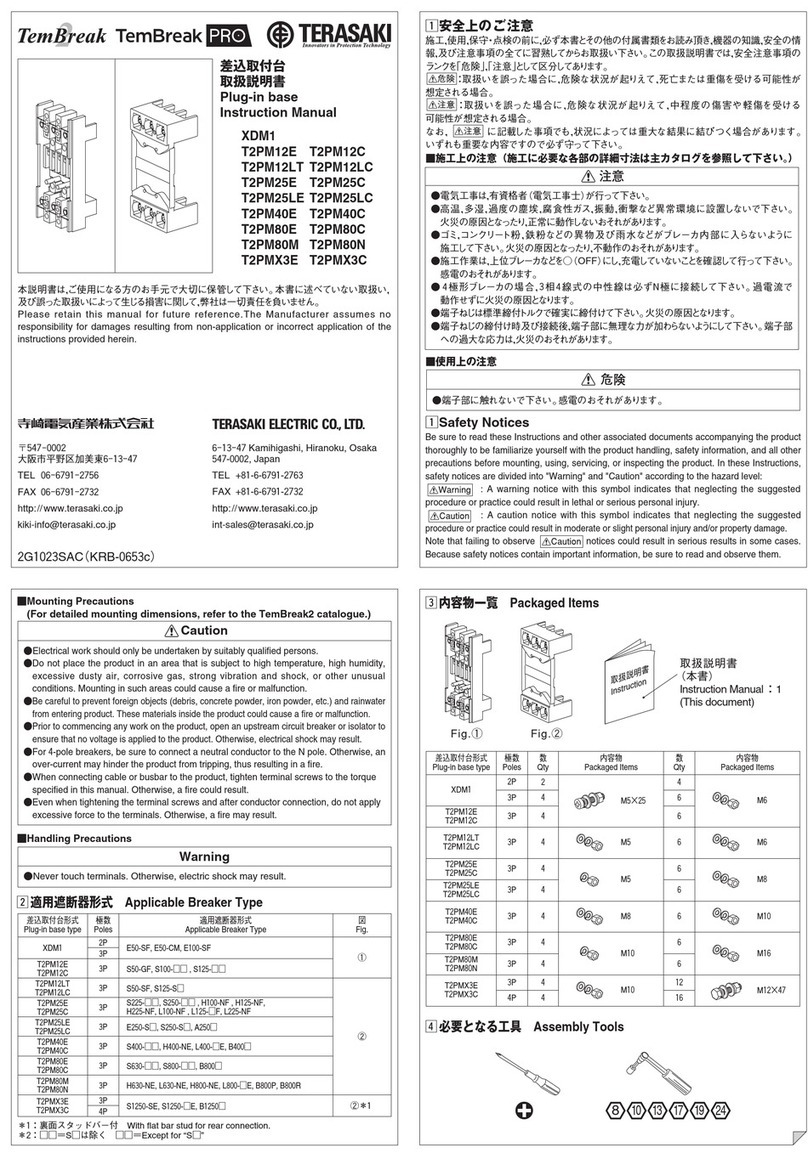
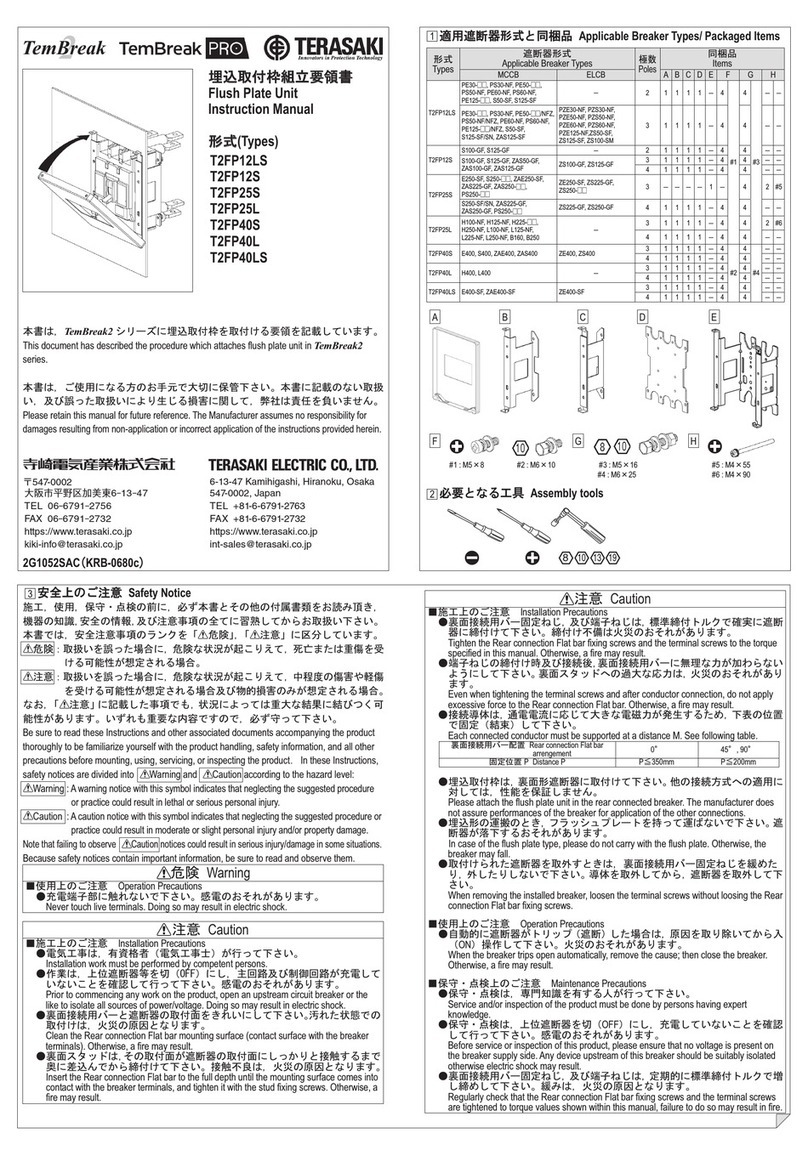
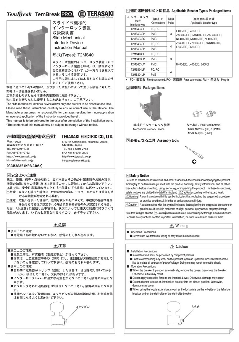
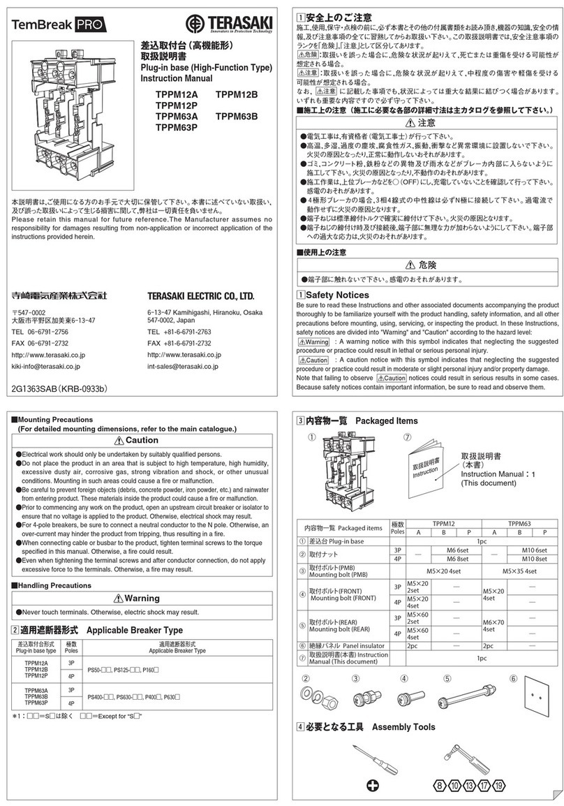
TERASAKI TemBreak 2 E125 User manual

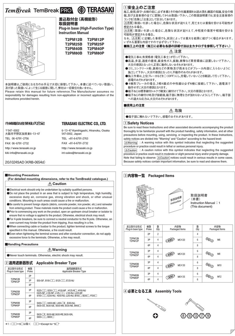
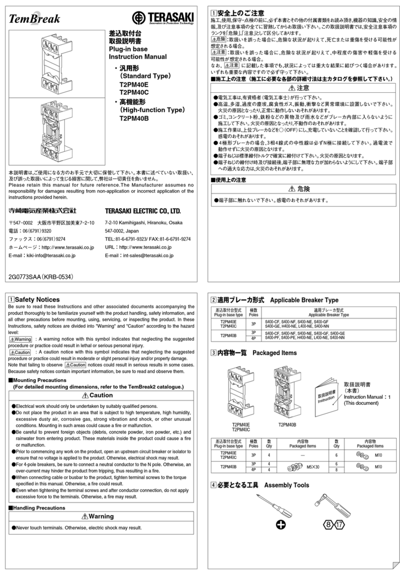
Plug-in Connection Unit
Instruction Manual
Types: E125 S125 H125 L125
E250 S250 H250 L250
H160 L160
This document has described the procedure which attaches Plug-in Connection unit in
TemBreak2 series.
Please retain this manual for future reference. The Manufacturer assumes no responsibility for
damages resulting from non-application or incorrect application of the instructions provided herein.
7-2-10 Kamihigashi, Hiranoku, Osaka
547-0002, Japan
TEL:81-6-6791-9323/ FAX:81-6-6791-9274
Web Site: www.terasaki.co.jp
Email: [email protected]
2G0617SAA (KRB-5309)
□
2Applicable Breaker Types/Packed Items
PC Unit
Items
Applicable Breaker Types Poles Code No.
A B C D E F
G
H
I
3 800009 6 1 - 4 6 -
1
2
-
E125,S125
4 800016
8 - 1 4 8 -
1
4
-
3 800023 6 1 - 4 - 6
1
2
-
E250,S250
4 800030
8 - 1 4 - 8
1
4
-
3 800061
6 1 - 4 - 6
1
-
2
H125,L125,H250,L250,H160,L160
4 800078
8 - 1 4 - 8
1
-
4
□
3Assembly tools
□
1Safety Notice
Be sure to read these Instructions and other associated documents accompanying the product
thoroughly to be familiarize yourself with the product handling, safety information, and all other
precautions before mounting, using, servicing, or inspecting the product. In these Instructions,
safety notices are divided into Caution according to the hazard level:
Caution :
A caution notice with this symbol indicates that neglecting the suggested procedure
or practice could result in moderate or slight personal injury and/or property damage.
Note that failing to observe Caution notices could result in serious injury/damage in some situations.
Because safety notices contain important information, be sure to read and observe them.
Caution
■Installation Precautions
●Clean the Plug-in Connection bolt mounting surface (contact surface with the breaker
terminals). Otherwise, a fire may result.
●Insert the Plug-in Connection bolt the full depth until the mounting surface comes into
contact with the breaker terminals, and tighten it with the PC bolt fixing screws.
Otherwise, a fire may result.
●Tighten the Plug-in Connection bolt fixing screws and carrier fixing screws to the torque
specified in this manual. Otherwise, a fire may result.
■Opration Precautions
●When the breaker trips open automatically, remove the cause; then close the breaker.
Otherwise, a fire may result.
■Maintenance Precautions
●Service and/or inspection of the product must be done by persons having expert
knowledge.
●Before service or inspection of this product, please ensure that no voltage is present on
the breaker supply side. Any device upstream of this breaker should be suitably
isolated otherwise electric shock may result.
●Regularly check that the Plug-in Connection bolt fixing screws are tightened to torque
values shown within this manual, failure to do so may result in fire.
D : φ4×12 E : M6×16 F : M6×20 GH : M4×55
BC
A
I : M4×115
□
4PC Unit Mounting Procedure
Please attach PC unit in front connected breaker.
◯
1Removal of I,J and K
<For E125,S125,E250,S250> <For H125,L125,H250,L250>
J K
3P:6pcs 3P:3pcs
4P:8pcs 4P:4pcs
L
3P:3pcs
4P:4pcs
◯
2Removal of M (for H125,L125,H250,L250)
◯
3Removal of N (for H125,L125,H250,L250)
◯
4
◯
6Cleaning
◯
7Insert
◯
8Check contact state
◯
9Tightening
M6×16
E 4.60~5.98N・m
M6×20
F 4.60~5.98N・m
◯
5Mount the carrier B or C to rear side of breaker.
M4×16
D
1.0~1.7N・m
Before mounting the carrier ,make sure that the breakers are in the I (ON) position.
◯
10 Stick the sticker G on the breaker body.
□
5Operation check
◯
1Turn ON the breaker and measure distance O.
◯
2Turn OFF the breaker and measure distance O.
◯
3Turn ON the breaker and measure distance P.
◯
4Turn OFF the breaker and measure distance P.
O
P
ON Min. 100 (mm)
O OFF
Max. 94 (mm)
ON 12.7-13.3 (mm)
P OFF
9.7-10.3 (mm)
OPEN THE MCCB
BEFORE MOUNTING
OR REMOVING.
MCCBをOFFにして
取付け・取外し下さい。
3㎜
4㎜
B or C
D
3P : 6pcs
4P : 8pcs
M
3P : 6pcs
4P : 8pcs
N
EorF
⑨
⑥
⑦
⑥
⑧(for E125,S125,E250,S250)
(for H125,L125,H250,L250)
A
G

This manual suits for next models

9

Other TERASAKI Circuit Breaker manuals

TERASAKI TemPower 2 User manual

TERASAKI

TERASAKI TemPower 2 User manual

TERASAKI AME Series User manual

TERASAKI

TERASAKI AME Series User manual

TERASAKI TemBreak PRO T2FP12LS User manual

TERASAKI

TERASAKI TemBreak PRO T2FP12LS User manual

TERASAKI TemBreak PRO TPPM12A User manual

TERASAKI

TERASAKI TemBreak PRO TPPM12A User manual

TERASAKI TemBreak PRO XDM1 User manual

TERASAKI

TERASAKI TemBreak PRO XDM1 User manual

TERASAKI TemBreak PRO T2MS4 User manual

TERASAKI

TERASAKI TemBreak PRO T2MS4 User manual

TERASAKI TemBreak 2 User manual

TERASAKI

TERASAKI TemBreak 2 User manual

TERASAKI TemPower 2 ACB User manual

TERASAKI

TERASAKI TemPower 2 ACB User manual

TERASAKI TemBreak 2 T2PM12B User manual

TERASAKI

TERASAKI TemBreak 2 T2PM12B User manual

TERASAKI TemPower2 AR-E Series User manual

TERASAKI

TERASAKI TemPower2 AR-E Series User manual

TERASAKI NHP TemBreak PRO P160 Series User manual

TERASAKI

TERASAKI NHP TemBreak PRO P160 Series User manual

Popular Circuit Breaker manuals by other brands

Siemens 3WN1 operating instructions

Siemens

Siemens 3WN1 operating instructions

Doepke DFS 4 NA Series Installation and operating instructions

Doepke

Doepke DFS 4 NA Series Installation and operating instructions

Allen-Bradley 140G Series Installation

Allen-Bradley

Allen-Bradley 140G Series Installation

Siemens 3VT9.00-1CC.2 manual

Siemens

Siemens 3VT9.00-1CC.2 manual

Siemens MBKJD1A installation instructions

Siemens

Siemens MBKJD1A installation instructions

Eaton W-VACi user manual

Eaton

Eaton W-VACi user manual

Linear Technology DC1198B-A Demo Manual

Linear Technology

Linear Technology DC1198B-A Demo Manual

Acrel ASCB1 Series Installation and operation manual

Acrel

Acrel ASCB1 Series Installation and operation manual

nader NDM3 Series product manual

nader

nader NDM3 Series product manual

ABB SACE Emax 2 E2.2 manual

ABB

ABB SACE Emax 2 E2.2 manual

CHINT NXBLE-125 Mounting instructions

CHINT

CHINT NXBLE-125 Mounting instructions

Westinghouse CAS-8 instructions

Westinghouse

Westinghouse CAS-8 instructions

Rockwell Automation Allen-Bradley 140U installation instructions

Rockwell Automation

Rockwell Automation Allen-Bradley 140U installation instructions

Leviton 46596 Installation

Leviton

Leviton 46596 Installation

SIMiONIC SHCB01 user manual

SIMiONIC

SIMiONIC SHCB01 user manual

ABB SACE Emax 2 Installation, operation and maintenance instructions

ABB

ABB SACE Emax 2 Installation, operation and maintenance instructions

Lovato SMX 11 Series Mounting instructions

Lovato

Lovato SMX 11 Series Mounting instructions

Siemens SIRIUS S2 Original operating instructions

Siemens

Siemens SIRIUS S2 Original operating instructions

manuals.online logo
manuals.online logoBrands
  • About & Mission
  • Contact us
  • Privacy Policy
  • Terms and Conditions

Copyright 2025 Manuals.Online. All Rights Reserved.