3R-F330—
|
CONTENTS
1.
OPERATING
INSTRUCTIONS...............-205.
ee
err
creer
2
MOC
VOW
«a
Ss
is
ao
Sb
Se
a
ne
ae
a
ead
erat
ed
ON
eh
ae
a
ey
2
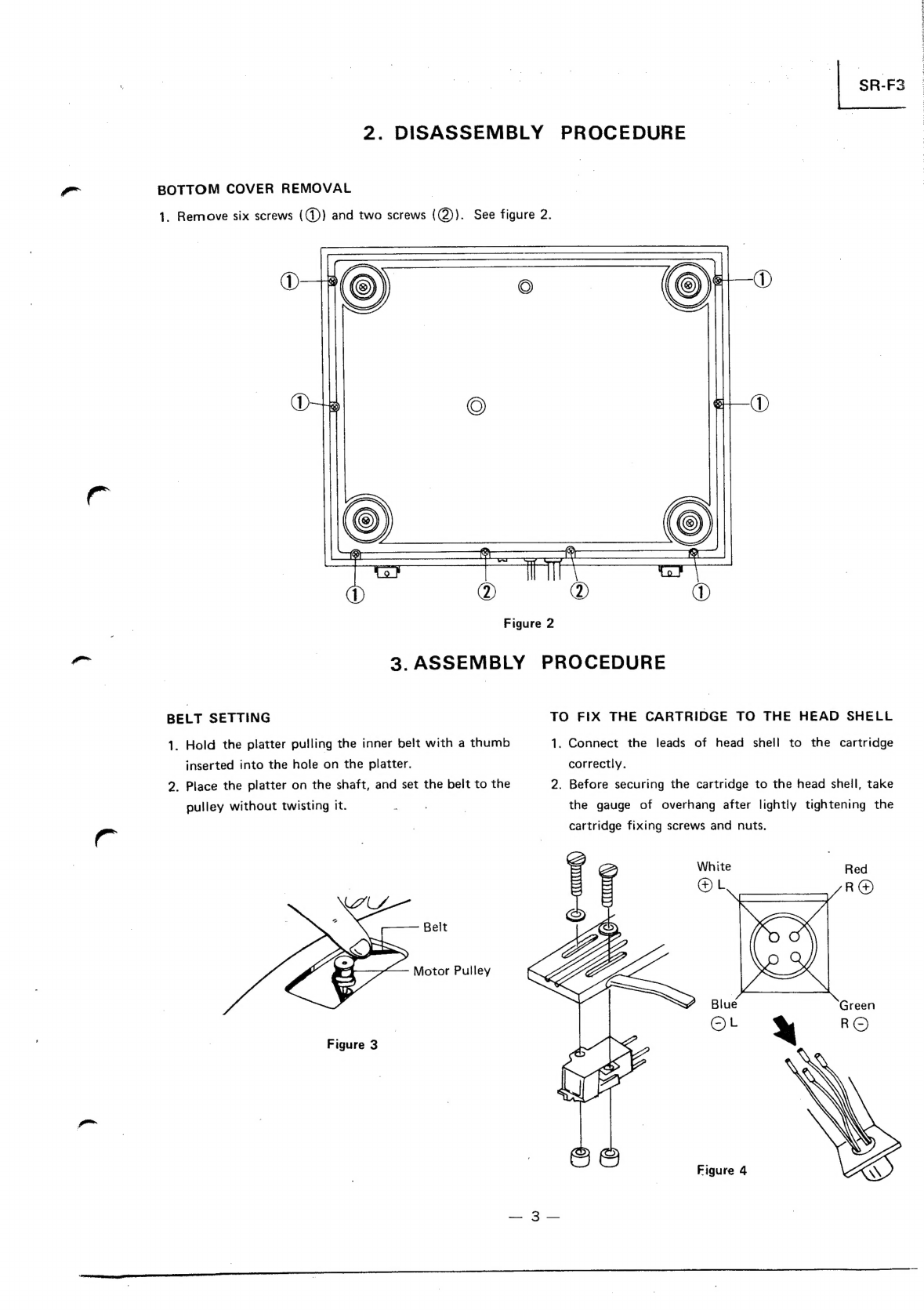
2.
DISASSEMBLY
PROCEDURE:
6.4
dc
Gree
wh
Se
RS
SO
Sr
es
Se
3
BOTTOM
COVER.
REMOVAL.
«4.605
éc8
eee
es
225
oo
eee
aR
ewe
ees
3
3.
ASSEMBLY
PROCEDURES
c55)cs
Shee
CRESS
SS
Lee
ede
ee
3
BELT
SEVIING
oie
oe
de
ce
eee
woes
Sb
be
Se
ee
ot
Se
ae
3
TO
FIX
THE
CARTRIDGE
TO
THE
HEAD
SHELL
...................
3
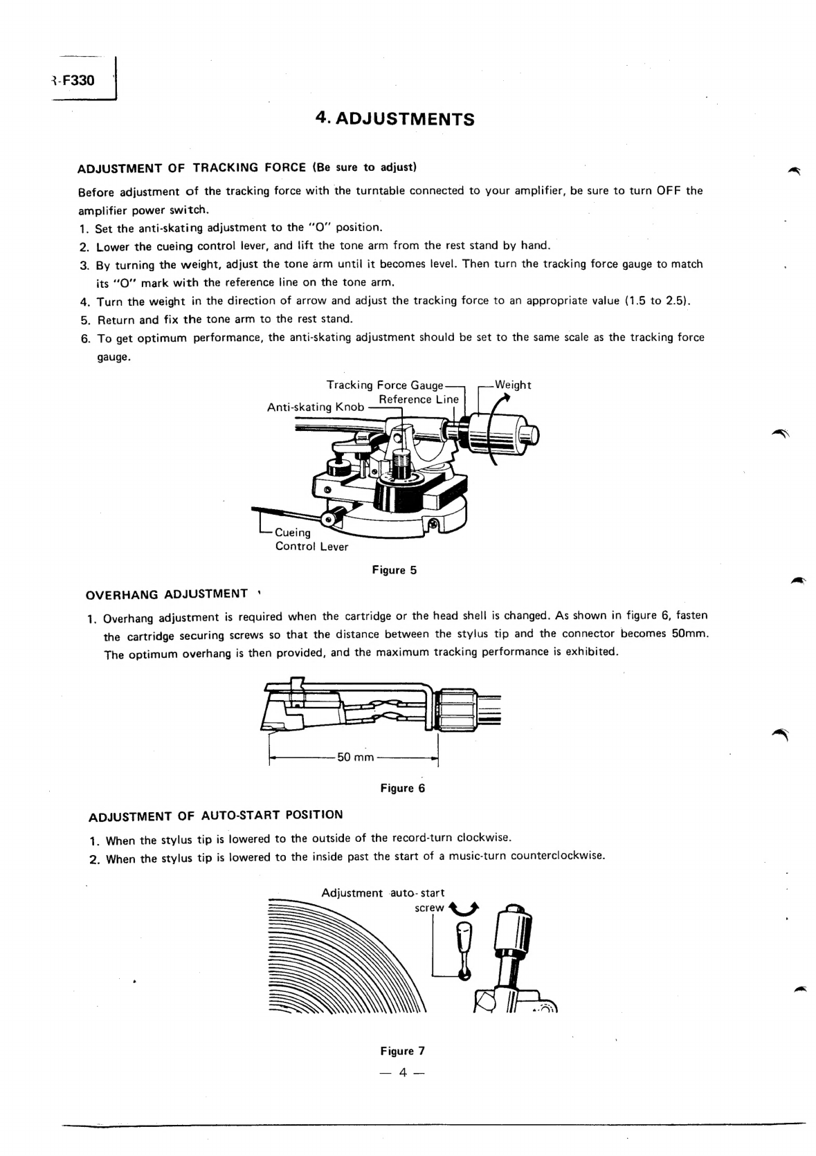
4.
ADIUSTMENTS:
:60c0.
eee
ik
Bie
Bh
Ge
et
OE
ee
4
and
9
ADJUSTMENT
OF
TRACKING
FORCE
(BE
sure
to
Adjust)
.............
4
OVERHANG
ADJUSTMENT.
5:
cnet
nes
ak
eS
keh
Sie
ee
Se
we
eS
4
ADJUSTMENT
OF
AUTO-START
POSITION
.............-..--..-202-
4
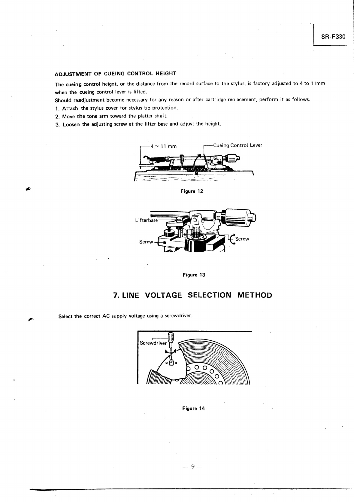
ADJUSTMENT
OF
CUEING
CONTROL
HEIGHT
................-.-..
9
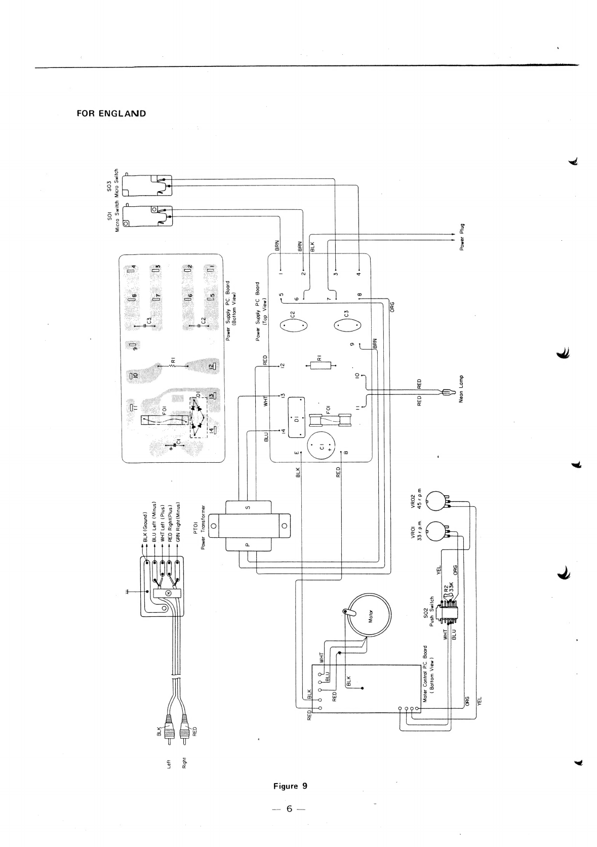
5.
WIRING
DIAGRAM
...........
2...
ccc
ce
ee
eee
ete
eee
5
to
7
FOR
EUROPE/AUSTRALIA.
.
2.005
were
se
bee
Sh
ee
eee
oe
wee
oe
5
FOR
ENGUAND:
6
ootcstwwsc
Ache
er
bs
6
ee
ees
ee
ee
PS
6
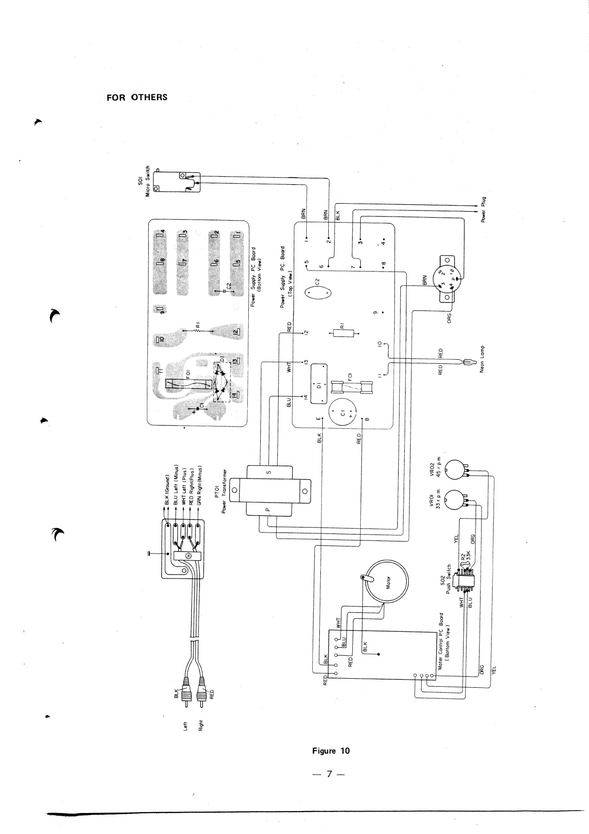
FOR
OTHERS
oct
Giere
wwe
toed
ese
see
st
cate
ees
ee
ee
7
6.
SCHEMATIC
DIAGRAM
.......-.-.
22-2
eee
ce
tee
eee
en
ete
nee
8
7.
LINE
VOLTAGE
SELECTION
METHOD
.................2-..-2-06--
9
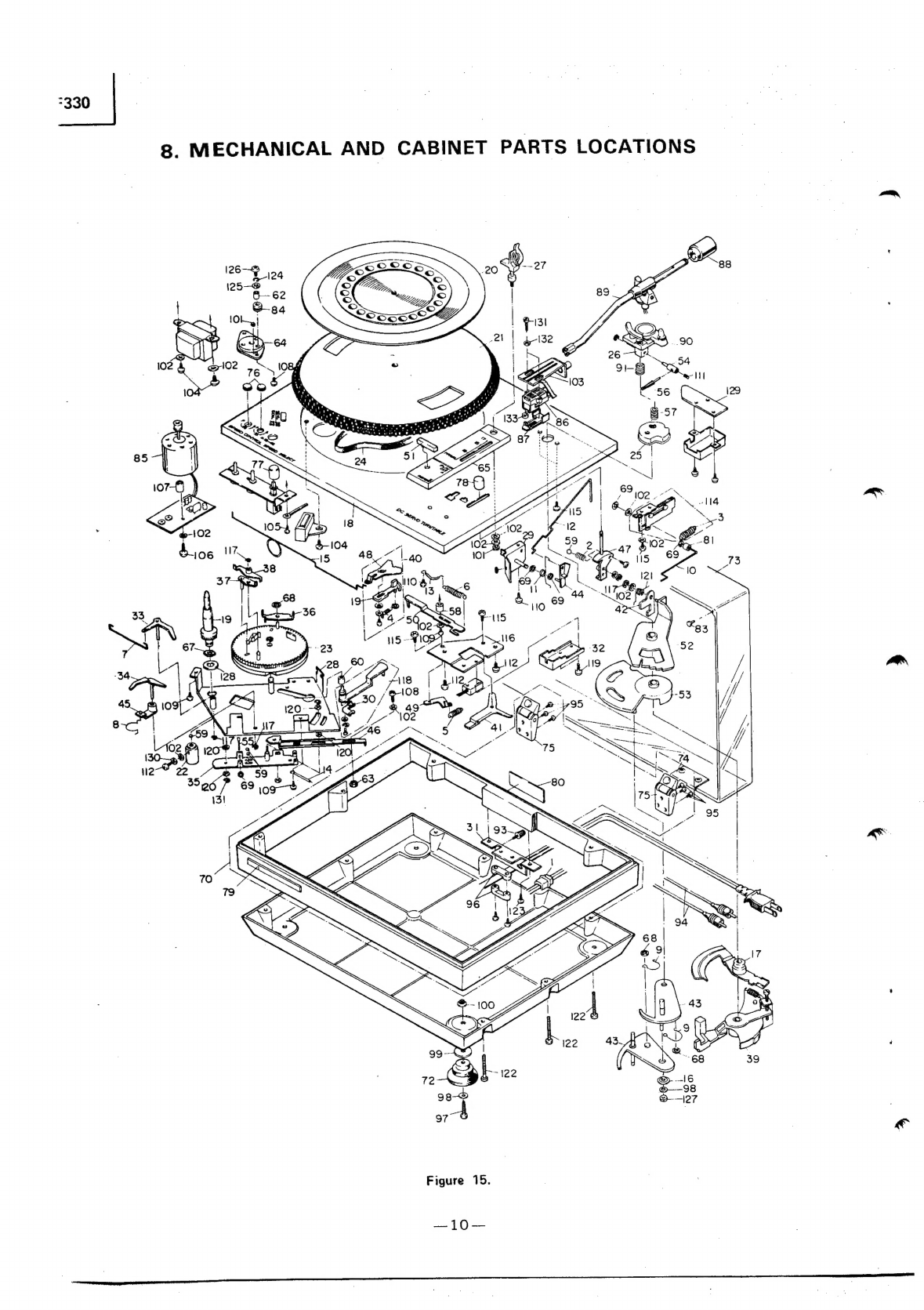
8.
MECHANICAL
AND
CABINET
PARTS
LOCATION
................-...
10
9.
PARTS
LIS!
3:4:2.60o5
2
ae
ee
oe
ees
Ee
Se
ee
11
1.
OPERATING
INSTRUCTIONS
TOP
VIEW
Weight
Platter
Sheet
Tone
Arm
Anti-skating
Platter
Cueing
Control
Lever
Shaft
Rest
Stand
Record
|
Select
Lever
Platter
Strobo
Light
Lever
(play,
cut
repeat)
Head
nae
Speed
Select
"=
65
ol
Figure
1