Toshiba 43VJ33P User manual

– SUMMARY –
43VJ33P is the same as 43VJ22P except for the parts tabled on back of this sheet.
Use this service manual together with the original service manual of
43VJ22P
(File No. 030-
200225).
FILE NO. 033-200312
SERVICE MANUAL
COLOUR TELEVISION
VJ33 Chassis
43VJ33P
PUBLISHED IN JAPAN, Jul., 2003 So

Location
No. Part No. Description
A110 23411886 Cabinet, Light Box
A201 23532205 Cover, Bezel Assy
A225 23445723 B tton, Power
A266 23450677 Panel, Pole SPK Grille (Right)
A268 23450678 Panel, Pole SPK Grille (Left)
C900 24214101 CD, 100pF, ±10%, 500V
C905 24214101 CD, 100pF, ±10%, 500V
D923 23115599 Diode, 1N4148
D961 23115599 Diode, 1N4148
DB21 23358564 Diode, LED, SLR-56VC3FPQ
DW22 23115599 Diode, 1N4148
K501 23311036 Screen, Lentic lar Sheet,
SCREEN43KNEL
K502 23311037 Screen, Fresnel Sheet,
SCREEN43KNEF
LV46 23103852 Coil, Filter, TEM2028AH
QB02 23114433 Transistor, 2SC1815-Y
R925 24366470 CF, 47 ohm
R933 24000921 FR, 1.2 ohm, 2W
R953 24366221 CF, 220 ohm
R962 24366241 CF, 240 ohm
R963 24366222 CF, 2200 ohm
R967 24366122 CF, 1200 ohm
R9801 24327180 MF, 18 ohm, ±1%, 1/4W
RA71 24366272 CF, 2700 ohm
RA73 24366113 CF, 11k ohm
RB02 24366471 CF, 470 ohm
RB20 24366101 CF, 100 ohm
RB21 24366103 CF, 10k ohm
*U901A 23761240 CRT-D/R Board, PD1439A-1
*U901B 23761241 CRT-D/G Board, PD1439A-2
*U901C 23761242 CRT-D/B Board, PD1439A-3
*U901F 23761245 SVM Board, PD1439A-4
*U902 23761376 SIGNAL Board, PD0817D
*U906A 23761373 FRONT IN Board, PD1103D-1
*U906B 23761374 RMT IN Board, PD1103D-2
*U906D 23761375 IND Board, PD1103D-4
* V911R 23587094 SERVICE KIT, PJTV CRT-R
* V912B 23587095 SERVICE KIT, PJTV CRT-B
* V913G 23587096 SERVICE KIT, PJTV CRT-G
Y101A 23566149 Owner’s Man al, Ehglish,
43VJ33P
Y101E 23566150 Owner’s Man al, E ro,
43VJ33P
REPLACEMENT PARTS LIST DIFFERENCES
TOSHIBA CORPORATION
1-1, SHIBAURA 1-CHOME, MINATO-KU, TOKYO 105-8001, JAPAN

TOSHIBA CORPORATION
1-1, SHIBAURA 1- CHOME, MINATO-KU, TOKYO 105-8001, JAPAN
FILE NO. 030-200225
SERVICE MANUAL
COLOUR TELEVISION
VJ13 Chassis
43VJ22P
PUBLISHED IN JAPAN, Sep., 2002 So

– 2 –
GENERAL ADJUSTMENTS
SPECIFIC INFORMATIONS
TABLE OF CONTENTS
CHAPTER 1 GENERAL ADJUSTMENTS
SAFETY INSTRUCTIONS ........................................................................................................................................ 3
CRT ASSEMBLY REPLACEMENT AND MOUNTING .............................................................................................. 4
PICTURE TUBE COMPONENTS ADJUSTMENT .................................................................................................... 6
SERVICE POSITION ................................................................................................................................................ 9
SERVICE MODE .................................................................................................................................................... 10
DESIGN MODE ...................................................................................................................................................... 13
ELECTRICAL ADJUSTMENT ................................................................................................................................. 14
CONVERGENCE ADJUSTMENT ........................................................................................................................... 15
SCREEN AND MIRROR ALIGNMENTS ................................................................................................................. 21
CIRCUIT CHECKS ................................................................................................................................................. 22
CHAPTER 2 SPECIFIC INFORMATIONS
SETTING & ADJUSTING DATA ............................................................................................................................. 23
LOCATION OF CONTROLS ................................................................................................................................... 24
MECHANICAL DISASSEMBLY .............................................................................................................................. 26
CHASSIS AND CABINET REPLACEMENT PARTS LIST ......................................................................................27
PC BOARDS BOTTOM VIEW................................................................................................................................. 41
TERMINAL VIEW OF TRANSISTORS ................................................................................................................... 50
CIRCUIT BLOCK DIAGRAM .................................................................................................................................. 52
SPECIFICATIONS .............................................................................................................................................. END
APPENDIX:
CIRCUIT DIAGRAM

–3 –
GENERAL ADJUSTMENTS
SPECIFIC INFORMATIONS
CHAPTER 1 GENERAL ADJUSTMENTS
SAFETY INSTRUCTIONS
WARNING: BEFORE SERVICING THIS CHASSIS, READ THE “X-RAY RADIATION PRECAUTION”, “SAFETY PRECAU-
TION”AND “PRODUCT SAFETY NOTICE”INSTRUCTIONS BELOW.
X-RAY RADIATION PRECAUTION
1. Excessive high voltage can produce potentially hazard-
ous X-RAY RADIATION. To avoid such hazards, the high
voltage must not be above the specified limit. The nominal
value of the high voltage of this receiver is (A) kV at zero
beam current (minimum brightness) under a (C) V AC power
source. The high voltage must not, under any circum-
stances, exceed (B) kV.
Refer to table-1 for high voltage (A), (B) & AC voltage (C).
(See SETTING & ADJUSTING DATA on page 23)
Each time a receiver requires servicing, the high voltage
should be checked following the HIGH VOLTAGE CHECK
procedure in this manual. It is recommended that the read-
ing of the high voltage be recorded as a part of the service
record. It is important to use an accurate and reliable high
voltage meter.
2. The only source of X-RAY RADIATION in this TV receiver
is the picture tube. For continued X-RAY RADIATION pro-
tection, the replacement tube must be exactly the same
type tube as specified in the parts list.
3. Some part in this receiver have special safety-related char-
acteristics for X-RAY RADIATION protection. For contin-
ued safety, parts replacement should be undertaken only
after referring to the PRODUCT SAFETY NOTICE below.
SAFETY PRECAUTION
WARNING : Service should not be attempted by anyone unfamiliar with the necessary precautions on this receiver. The following
are the necessary precautions to be observed before servicing this chassis.
1. An isolation transformer should be connected in the power line between the receiver and the AC line before any service is
performed on the receiver.
2. Always discharge the picture tube anode to the CRT conductive coating before handling the picture tube. The picture tube
is highly evacuated and if broken, glass fragments will be violently expelled. Use shatter proof goggles and keep picture tube
away from the unprotected body while handling.
3. When replacing a chassis in the cabinet, always be certain that all the protective devices are put back in place, such as; non-
metallic control knobs, insulating covers, shields, isolation resistor-capacitor network etc.
PRODUCT SAFETY NOTICE
Many electrical and mechanical parts in this chassis have special safety-related characteristics. These characteristics are
often passed unnoticed by a visual inspection and the protection afforded by them cannot necessarily be obtained by using
replacement components rated for higher voltage, wattage, etc. Replacement parts which have these special safety char-
acteristics are identified in this manual and its supplements; electrical components having such features are identified by
the international hazard symbols on the schematic diagram and the parts list.
Before replacing any of these components, read the parts list in this manual carefully. The use of substitute replacement
parts which do not have the same safety characteristics as specified in the parts list may create shock, fire, X-ray
radiation or other hazards.

–4 –
GENERAL ADJUSTMENTS
SPECIFIC INFORMATIONS
CRT ASSEMBLY REPLACEMENT AND MOUNTING
CAUTION : DO NOT LOOSEN THE HEX HEAD BOLTS WITH SPRINGS (12 PCS), BECAUSE THOSE ARE FOR
SEALING OF CRT COOLANT.
Lens and Neck Components View
4 Screws
CRT Anode Cap Assembly
S.V.M. Coil
CRT DRIVE Board
Lens Assembly
CRT Assembly
Deflection Yoke and Conver Yoke
CRT Mounting
4 Screws
Attention Serviceman
The Hex Head
Bolts with
Springs. (see
sketch) used on
CRT assembly,
are “NOT”
Adjustment Screws
DO NOT LOOSEN-FLUID
LEAKAGE WILL OCCUR.

–5 –
GENERAL ADJUSTMENTS
SPECIFIC INFORMATIONS
SERVICING PRECAUTIONS
■Check the point of anode lead in a straight
line, if it is winding, please revise it.
Anode lead holder
■Do not use a magnetized screw driver for screws
of Deflection Yoke and Velocity Modulation Coil to
avoid magnetization of electron gun.
Magnetization of electron gun will degrade basic
function and result in unbalance of right and left
shift of user static convergence, and result in no
variable quantity.
■When replacing the anode cap assembly (CRT) or
anode lead assembly (F.B.T.), remove the anode
lead holder from old one and attach the holder
again to new anode lead.
Screw
for D.Y
Screw for SVM coil
Silicon
(On shaded area)
TSE3843W #23960136
2 ~ 5 mm
15 ~ 25 mm
Anode Cap
TO REMOVE CRT (Same procedure for R, G, B)
1. Remove CRT DRIVE Board, S. V. M. COIL and
DEF. YOKE from CRT.
2. Remove Lens Assembly.
3. Detach CRT Anode Cap from CRT.
4. Remove CRT Assembly from CRT Mounting.
CRT REPLACEMENT (Same procedure for R, G, B)
Reverse the removal procedures except the followings.
1. Anode Cable should be replaced with new one.
See "SERVICING PRECAUTIONS" shown below.
2. Install silicon (T461B) to the CRT, replace the Anode
cable and put enough silicon again on around the An-
ode Cap as illustrated.
CAUTION: Align the Anode cable as illustrated on page
4.
ADJUSTING PROCEDURE IN REPLACING CRT
1. R.G.B. CUTOFF (SCREEN VR) ADJUSTMENT (page 6.)
2. R.G.B. FOCUS ADJUSTMENT (page 6.)
3. PICTURE TILT ADJUSTMENT (page 7.)
4. USER CONVERGENCE CENTER CHECK
(Refer to owner's manual.)
5. CENTERING ADJUSTMENT (page 7.)
6. CONVERGENCE ADJUSTMENT (page 20.)
7. WHITE BALANCE ADJUSTMENT (page 14.)
Adjustments are complete.

–6 –
GENERAL ADJUSTMENTS
SPECIFIC INFORMATIONS
WARNING: BEFORE SERVICING THIS CHASSIS, READ THE "X-RAY RADIATION PRECAUTION", "SAFETY PRE-
CAUTION" AND "PRODUCT SAFETY NOTICE" ON PAGE 3 OF THIS MANUAL.
PICTURE TUBE COMPONENTS ADJUSTMENT
ADJUSTING PROCEDURE IN REPLACING CRT
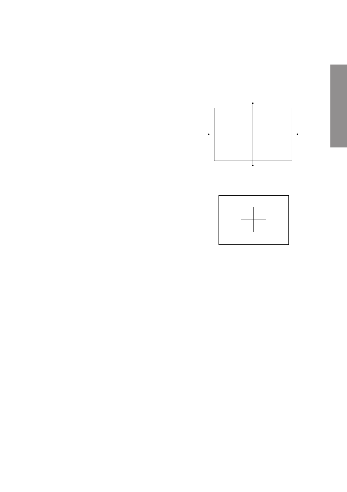
User convergence center check
Lens focus
Electrical focus
Cutoff
Centering (PAL)
Convergence adjustment
(PAL/NTSC)
Yoke horizontal
End
Sub bright adjustment
White balance
DESCRIPTION OF NECK COMPONENTS
1Deflection yoke and convergence yoke.
The position on the neck is required most front (CRT fun-
nel side) and the screw is fastened after rotating yoke
adjusting picture tilt.
2Centering magnet
After adjusting picture tilt, picture position is finally fixed
by this magnet.
In order to get maximum margin of user convergence con-
trol for center of screen, this magnet have to be used for
center convergence adjustment.
PREPARATION
Operate the receiver for at least 5 minutes.
R, G, B CUTOFF (SCREEN VR) ADJUSTMENT
1. Adjust before replace the screen assembly.
2. Set user control to reset position.
(CONTRAST →Max
BRIGHTNESS, COLOR, TINT →Center. )
3. Call up the adjustment mode display, then select the
item RCUT.
4. Adjust the data of items RCUT,GCUT, and BCUT to
"40H".
5. Press the -/-- button on Remote. (Y-MUTE : ON)
6. Gradually rotate R, G and B screen volume of FOCUS
PAC clockwise or counterclockwise until the raster
appears slightly on the CRT through the each lens, and
leave them.
(Lookin to the lens in order to check the raster.)
7. Press the -/-- button on Remote. (Return to Normal
Picture)
1
2
S.V.M. COIL
RGB FOCUS ADJUSTMENT
1. Connect a VIDEO signal generator which generates a
cross-hatch pattern.
2. Receive a white cross-hatch pattern by pressing the signal
slection key on the VIDEO signal generator.
3. Expose only RED by covering the GREEN and BLUE
lenses with caps.
4. Loosen the RED lens fixing screws (refer to Fig. a), and
adjust the RED lens focus to obtain the sharpest point
while observing the middle and peripheral sections of the
screen.
Fig. a
5. Use the focus VR of “R”of the focus pack in order to adjust
the electric focus in the middle and peripheral sections of
the screen to its sharpest level.
6. Check the RED focus of the whole screen and if necessary
repeat steps 4 and 5.
7. Fix the RED lens by tightening its fixing screws.
8. Expose only GREEN by covering the RED and BLUE
lenses with caps.
9. Display the internally-generated cross-hatch signal.
10. Adjust the GREEN lens focus on the left border of the
screen to its sharpest level, then check the focus on the
right border, and if it is at its sharpest level, fix it in that
position by tightening the lens screws.
(1) If the horizontal line toward the right border is red-
flared, turn the lens screw slightly right in order to
balance it with the left border. (After adjustment, the
left border tends to be slightly green-flared, and the
right border tends to be slightly red-flared.)
(2) If the horizontal line toward the right border is green-
flared, turn the lens screw slightly left in order to
balance it with the left border. (After adjustment, the
left border tends to be slightly red-flared, and the
right border tends to be slightly green-flared.)
Note: The aim of the above-described adjustment procedure
for the Green lens focus is to obtain the best lens focus
after 2 - 3 hours of warming up taking into account the
focus drift; it applies if the warming up time before the
adjustment is less than 30 minutes. (The horizontal line
in the screen middle section tends to be slightly red-
flared.)

–7 –
GENERAL ADJUSTMENTS
SPECIFIC INFORMATIONS
In case of warming up of more than 2 hours under a condition
that the large anode current is running through the projection
tube so that for example the all-white pattern appears, adjust
to obtain the sharpest focus while observing the whole screen
like in the RED case.
11. Use the focus VR of “G”of the focus pack in order to ad-
just the electric focus in the middle section of the screen
to its sharpest level.
Note: Normally the most clearly visible point of the scanning
line is the sharpest point of the Green focus, however as
the characteristics vary depending on the projection tube,
the sharpest focus points of the vertical and horizontal
lines may not match each other, thus when you turn the
focus VR, if the picture tends to be tremendously unstable
(rolls horizontally or vertically), adjust the balance of the
vertical and horizontal lines to its best position.
12. Check the GREEN focus of the whole screen and if
necessary repeat steps 10 and 11.
13. Fix the GREEN lens by tightening up its fixing screws.
14. Expose only BLUE by covering the RED and GREEN
lenses with caps.
15. Loosen the BLUE lens fixing screws (refer to Fig. a), and
adjust the BLUE lens focus while observing the middle
and peripheral screen sections.
16. Use the focus VR of “B”of the focus pack in order to adjust
the focus in the middle section of the screen to its sharpest
level.
(The point of the Blue focus becomes sharpest when the
brightness level of BLUE is lowest, the cross-hatch is
clearly visible.)
17. Check the BLUE focus of the whole screen and if neces-
sary repeat steps 15 and 16.
18. Fix the BLUE lens by tightening its fixing screws.
TILT ADJUSTMENT
Rotate R, G, B deflection yoke so that picture becomes hori-
zon, then fasten screw.
CENTERING ADJUSTMENT
1. Stretch threads towards the center of the screen (top and
bottom, left and right).
2. Enter to the user's Convergence Adjustment Mode from
the menu.
3. Adjust G centering magnet so that the cross pattern cen-
ter comes to screen center.
4. Perform HEIGHT adjustment . (See page 14.)
5. Perform VERT. LINEARITY adjustment. (See page 14.)
6. Perform WIDTH adjustment. (See page 14.)
7. Check whole quality of green line.
8. Adjust R, B centering magnet so that the cross pattern
center comes to screen center.

–8 –
GENERAL ADJUSTMENTS
SPECIFIC INFORMATIONS
LOCATION OF SCREEN AND FOCUS VR'S
To remove the Speaker grille and Front panel.
SCREEN VR's
Front panel Speaker grille
FOCUS VR's
RG
B
REPLACEMENT OF HIGH VOLTAGE CABLE
ANODE LEAD
RUBBER BOOT
LEAD HOLDER
Z450 TPA5007
Fig. a
1. When replacing Anode Lead or Anode Cap with new
one, remove Lead Holder from old lead as shown in
figure below, and put it on new lead. Do not throw away
Lead Holder.
NOTE : THE LEAD HOLDER IS ATTACHED TO
TPA5007 (Z450), BUT IS NOT ATTACHED TO
ANODE LEAD AND ANODE CAP. RUBBER
BOOT IS ATTACHED TO ANODE LEAD AND
ANODE CAP.
2. Detaching Lead Holder
RUBBER BOOT
OLD
ANODE LEAD
or
ANODE CAP
LOCK LEAD HOLDER Cut here rubber boot
and lead together to
detach Lead Holder.
Fig. b

–9 –
GENERAL ADJUSTMENTS
SPECIFIC INFORMATIONS
WARNING: BEFORE SERVICING THIS CHASSIS, READ THE "X-RAY RADIATION PRECAUTION", "SAFETY PRE-
CAUTION" AND "PRODUCT SAFETY NOTICE" ON PAGE 3 OF THIS MANUAL.
SERVICE POSITION
In order to assure the performance, processed wires shall be replaced after the repair work.
Work procedures are as follows:
1. Remove the back board.
2. Remove lead wires.
3. Draw out the chassis.
4. Rest the chassis against the back cabinet, chassis as shown bellow.
After repair work finished, replace it in the opposite procedure.

–10 –
GENERAL ADJUSTMENTS
SPECIFIC INFORMATIONS
SERVICE MODE
1. ENTERING TO SERVICE MODE
S
(Service mode display)
Item
Data
or Sound Mute
3) While pressing the obutton,
press MENU button on TV set.
2) Press obutton again to
keep pressing.
2. DISPLAYING THE ADJUSTMENT MENU
1) Press MENU button on TV.
3. KEY FUNCTION IN THE SERVICE MODE
The following key entry during display of adjustment menu provides special functions.
Screen adjustment mode ON/OFF: -/-- button (on Remote)
Test signal selection : abutton (on Remote)
Selection of the adjustment items : Channel s/t(on TV or Remote)
Change of the data value : Volume ;+/–(on TV or Remote)
Adjustment menu mode ON/OFF : MENU button (on TV)
Initialization of the memory (QA02) : CALL + Channel button on TV (s)
Reset the count of operating protect
circuit to “00”: CALL + Channel button on TV (t)
“RCUT”selection : 1 button
“GCUT”selection : 2 button
“BCUT”selection : 3 button
“SCNT”selection (in BRTC VIDEO mode): 4 button
“COLP”selection : 5 button
“TNTC”selection : 6 button
Convergence adj : YELLOW button
Self diagnostic display ON/OFF : 9 button
1) Press obutton once on
Remote Control.
Adjustment mode
Press
Press
Service mode
Item
Data
S
Color thickness correction
note: Displayed differently as shown below, de-
pending on the setting of the receiving color
system.
COLP (PAL)
COLC (NTSC)
COLS (SECAM)
CAUTION : Never try to perform initialization unless you have changed the memory IC.

–11 –
GENERAL ADJUSTMENTS
SPECIFIC INFORMATIONS
4. SELECTING THE ADJUSTING ITEMS
1) Every pressing of CHANNEL sbutton in the service mode changes the adjustment items in the order of table-2.
(tbutton for reverse order)
Refer to table-2 for preset data of adjustment mode.
(See SETTING & ADJUSTING DATA on page 23)
5. ADJUSTING THE DATA
1) Pressing of VOLUME ;+/–button will change the value of data in the range from 00H to FFH. The variable
range depends on the adjusting item.
6. EXIT FROM SERVICE MODE
1) Pressing POWER button to turn off the TV once.
■INITIALIZATION OF MEMORY DATA OF QA02
After replacing QA02, the following initialization is required.
1. Enter the service mode, then select any register item.
2. Press and hold the CALL button on the Remote, then press the CHANNEL sbutton on the TV. The initialization of QA02 has
been complated.
3. Check the picture carefully. If necessary, adjust any adjustment item above.
Perform “Auto search Memory”on the owner’s manual.
CAUTION: Never attempt to initialize the data unless QA02 has been replaced.
7. TEST SIGNAL SELECTION
1) Every pressing of abutton on the Remote Control changes the built-in test patterns on screen as described below
in SERVICE MODE.
Signals Picture
•Red raster
•Green raster
•Blue raster
•All White
•Black cross-hatch
* The signals marked with are not usable to display in the Test signal for some model.
Signal off PAL signals (5 patterns)
NTSC signals (5 patterns)

–12 –
GENERAL ADJUSTMENTS
SPECIFIC INFORMATIONS
8. SELF DIAGNOSTIC FUNCTION
1) Press “9”button on Remote Control during display of adjustment menu in the service mode.
The diagnosis will begin to check if interface among IC’s are executed properly.
2) During diagnosis, the following displays are shown.
2300* * * *(SAA556* PS/M3/* * * *)
TIME : 000000
POWER : 0
BUS LINE : OK
BUS CONT : OK
BLOCK : UV V1 V2 V3
<SELF CHECK
Part number of microcomputer (QA01)
Total hour of turn the TV on. (Unit: H)
Operation number of protecting circuit ----“00”is nor-
mal.
When indication is other than “00”, overcurrent apts to
flow, and circuit parts may possibly be damaged.
BUS LINE ----“OK”is normal.
When indication shows “SDA-GND”, the SDA line may
possibly be shorted to GND..
BUS CONT ----“OK”is normal.
When indication shows “Q uuu NG”, the device with
the number may possibly be damaged.
BLOCK
UV : TV reception mode
V1 : VIDEO 1 input mode (a1)
V2 : VIDEO 2 input mode (a2)
V3 : VIDEO 3 input mode
V4 : VIDEO 4 input mode
Indicated color of mode now selected : Green and Red
Indicated color of other modes : Black
Green : Normal
Red : The microcomputer operates to provide judgement
of no video signal. The red color is still indicated
though the signal is input, failure may exist in input
signal line including QV01.
NOTE: (1) In case that "on timer" indicator is blinking with
interval of 0.5 seconds; it means protecting
circuit (Current limiter) is operating, and cir-
cuit components may possibly be damaged.
Check related components.
(2) In case that "on timer" indicator is blinking with
interval of 1 second; Protecting circuit does
not operate, but a part of Bus line does not
operate normally. Check Bus line.
* The items marked with are not usable to display in the SELF DIAGNOSTIC FUCTION for some model.

–13 –
GENERAL ADJUSTMENTS
SPECIFIC INFORMATIONS
DESIGN MODE
1. ENTERING TO DESIGN MODE
ITEM
DATA
S D Press
(Design mode) (Adjustment mode)
Press
3) Press MENU button on TV.
2) While pressing CALL button on Remote
and press MENU button on TV.
1) Select the Service mode.
2. SELECTING THE ADJUSTING ITEMS
Every pressing of CHANNEL tbutton in the design mode changes the adjustment items in the order of table-3.
(sbutton for reverse order)
Refer to table-3 for data of design mode.
(See SETTING & ADJUSTING DATA on page 23)
3. ADJUSTING THE DATA
Pressing of VOLUME sor tbutton will change the value of data.

–14 –
GENERAL ADJUSTMENTS
SPECIFIC INFORMATIONS
ITEM ADJUSTMENT PROCEDURE
1. Call up the adjustment mode display, then select the item WID.
2. Press the VOLUME tbutton to get the picture so the left
or right edges of raster begins to lack.
3. Press the VOLUME sbutton to advance the data by 12
steps.
Note : Check the horizontal picture position is correct.
WIDTH
(WID)
VERTICAL LINEARITY
(VLIN)
1. Call up the adjustment mode display, then select the item VLIN.
2. Receive the cross-hatch pattern which appears on the screen by the signal
generator.
3. Press the VOLUME sor tbutton to
obtain the picture of the best linearity
Center
1. Call up the adjustment mode display, then select the item HIT.
2. Press the VOLUME tbutton to get the picture so the top or bottom of
raster begins to lack.
3. Press the VOLUME sbutton to advance the data by 11 steps.
Note : Check the vertical picture position is correct.
Black and White pattern
High light area
Adjust "RDRV" or "BDRV" to be white.
Low light area
Fine adjust "RCUT", "GCUT" or "BCUT" to be black.
1. Set user control to reset position.
(CONTRAST →Max
BRIGHTNESS, COLOR, TINT →Center. )
2. Call up the adjustment mode display, then select the item RCUT.
3. Adjust the data of items RCUT,GCUT, and BCUT to "40H".
4. Press the -/-- button on Remote. (Y-MUTE : ON)
5. Gradually rotate R, G and B screen volume of FOCUS PAC clockwise or coun-
terclockwise until the raster appears slightly on the CRT through the each lens,
and leave them.
(Lookin to the lens in order to check the raster.)
6. Press the -/-- button on Remote. (Return to Normal Picture)
7. Press the abutton on Remote, and select the Black and White pattern.
8. Adjust the data of items RCUT, GCUT and BCUT for proper white-balanced
picture in low light area.
9. Adjust the data of items RDRV and BDRV for proper white-balanced picture in
high light area.
10. Check the white balance in both low and high light areas.
If necessary, perform again steps from 8 to 9.
ELECTRICAL ADJUSTMENT
HEIGHT
(HIT)
WHITE BALANCE
(RCUT)
(GCUT)
(BCUT)
(RDRV)
(BDRV)

–15 –
GENERAL ADJUSTMENTS
SPECIFIC INFORMATIONS
CONVERGENCE ADJUSTMENT
1. SCREEN ADJUSTMENT
The adjustment is carried out on four screens; 4 : 3 and 16 : 9
screens in both PAL and NTSC modes. When making the ad-
justments, feed an external signal to make an synchroniza-
tion.
Note:
The convergence circuit is a circuit to eliminate screen distor-
tion and can not make a drastic correction such as to correct
entire screen size. An excessive correction may actuate the
protection circuit. So a care will be necessary.
Before proceeding to the adjustment for each screen, always
perform the adjustments for vertical size (HIT) and horizontal
size (WID) with the main deflection data changed.
Order of the adjusting screens is PAL 4 : 3 →PAL 16 : 9 →
NTSC 4 : 3 →NTSC 16 : 9.
The menu order is 1 →2 →3 .... when the vertical sync is 50
Hz. (In this case, item 4~6 are not displayed)
The menu order is 4 →5 →6 .... when the vertical sync is 60
Hz. (In this case, item 1~3 are not displayed)
1-1. Entering the Adjustment Menu
Fig. 1
Conver Adjust MENU
1. Adjust PAL (50 Hz) 4:3
2. PALL 4:3 to Others
3. Adjust PAL 16:9
Conver Adjust MENU
4. Adjust NTSC (60 Hz) 4:3
5. NTSC 4:3 to NTSC 16:9
6 Adjust NTSC 16:9
or
When receiving
PAL (50Hz)
When receiving
NTSC (60Hz)

–16 –
GENERAL ADJUSTMENTS
SPECIFIC INFORMATIONS
aokey ............... Push this key twice and the set con-
sole menu key to enter the service
mode.
b7 key ................. Push 7 key to enter and cancel the
convergence menu.
g5 key ................. Cursor shift / data change mode
change-over.
h2 key ................. Cursor up / adjusting point up.
i4 key ................. Cursor left / adjusting point left
j8 key ................. Cursor down / adjusting point down
k6 key ................. Cursor right / adjusting point right
l3 key ................. Cursor colour change (Adjusting
colour selection).
mSkey ................ Execution key on convergence menu.
nskey ................ Up key on convergence menu.
otkey ................ Down key on convergence menu.
1-2. Remote Control Key
Fig. 2
CALL
456
7
MENU
TV
VCR
DVD
R
GY
B
DVD
MENU
EXIT
89
0
123
h
i
g
j
n
o
b
k
a
m
l

–17 –
GENERAL ADJUSTMENTS
SPECIFIC INFORMATIONS
2. Picture
a) 50 Hz mode (PAL) . . . . Correcting point: Horizontal 8 xVertical 8 (Arrow marks denote correcting point)
The first picture
Crosshatch pattern. Pattern colors are three color display. Cur-
sor is blinking in red. When changed, condition is last memory
state.
Cursor is .......... Data change mode in lighting,
Cursor shifting mode in blinking.
Display color shows the color that data change is possible.
(Note: Red is displayed in yellow.)
The second picture
When entering from the first picture to the second picture, cor-
recting wave of convergence is muted for one second.
During this period, the changed data is transferred from RAM
Q701 to E2PROM Q711, and saved.
The second picture is indicated with data on top left of the first
picture, therefore, convergence cannot be adjusted by this pic-
ture.
Caution:
,Receive suitable signal for adjustment. Centering of
green picture can be done in 50 Hz mode (PAL).
,Centering of 60 Hz mode (NTSC) can be adjusted by
convergence adjustment. Besides, decide the center
by cross pattern of static convergence in menu, and
adjust convergence from center to circumference.
Data display
Screen centerCursor (red)
(Blinking)
The first picture The second picture

–18 –
GENERAL ADJUSTMENTS
SPECIFIC INFORMATIONS
b) 60 Hz mode (NTSC) . . . . Correcting point: Horizontal 8 xVertical 7 (Arrow marks denote correcting point)
Data display
The first picture The second picture
Cursor (red)
(Blinking)
Screen center
The first picture
Crosshatch pattern. Pattern colors are three color display. Cur-
sor is blinking in red. When changed, condition is last memory
state.
Cursor is .......... Data change mode in lighting,
Cursor shifting mode in blinking.
Display color shows the color that data change is possible.
The second picture
When entering from the first picture to the second picture, cor-
recting wave of convergence is muted for one second.
During this period, the changed data is transferred from RAM
Q701 to E2PROM Q711, and saved.
The second picture is indicated with data on top left of the first
picture, therefore, convergence cannot be adjusted by this pic-
ture.
Caution:
,Receive suitable signal for adjustment. Decide the center
by cross pattern of static convergence in menu, and adjust
convergence from center to circumference.
Table of contents
Other Toshiba TV manuals

Toshiba
Toshiba 27A14 User manual

Toshiba
Toshiba 40LV733G User manual

Toshiba
Toshiba 38VL14G User manual

Toshiba
Toshiba Z3030 Series User manual

Toshiba
Toshiba 27AF43 User manual

Toshiba
Toshiba 21V53G User manual

Toshiba
Toshiba 21V53 User manual

Toshiba
Toshiba 19SL410U User manual

Toshiba
Toshiba 20A44 User manual

Toshiba
Toshiba 24W3753DB User manual

Toshiba
Toshiba MD20FM1C User manual

Toshiba
Toshiba MV19K3C User manual

Toshiba
Toshiba 29SZ5DA User manual

Toshiba
Toshiba 34AX9UH User manual

Toshiba
Toshiba 43U6763DB User manual

Toshiba
Toshiba 32HFX71 User manual

Toshiba
Toshiba 27A33 User manual

Toshiba
Toshiba TV User manual

Toshiba
Toshiba MD20H63 Service manual

Toshiba
Toshiba CF19H22 User manual