TOTAL FLEX L User manual

User’s Guide

TABLE OF CONTENTS
A. Notice .................................................................................................1
B. Important Safety Notice..................................................................... 1 - 2
C. Total Flex™ L Main Components ......................................................3
D. Assembling the Total Flex™ L ...........................................................4
Power Rod Assembly .................................................................................4
Leg Extender Assembly ............................................................................4 - 6
E. Setting Up the Total Flex™ L ............................................................7
Opening the Total Flex™ L ........................................................................7
Inserting the Foot Plate .............................................................................7
Adjusting the Seats ....................................................................................8 - 9
F. Use Of Attachments .........................................................................10
1. Power Pods ...............................................................................................10
2. Handles .....................................................................................................11 - 12
3. Ankle Cuffs ..............................................................................................13
4. Foot Plate ..................................................................................................13
5. Head Rest .................................................................................................13 - 14
6. Leg Extender ...........................................................................................14 - 15
G. Exercise Resistance ...........................................................................16
H. Storing the Total Flex™ L ..................................................................16 - 17
I. Maintaining the Total Flex™ L ..........................................................17
General Maintenance .................................................................................17
Resistance Bands ........................................................................................18 - 19
J. Total Flex™ L Tips and Suggestions .................................................20

A. Notice
B. IMPORTANT SAFETY NOTICE
Important: Do not start exercising before fully studying this User’s
Guide and Exercise Chart.
• Use this User’s Guide in conjunction with the Exercise Chart and the Total Flex™ L
Online Streaming Workout Videos.
• This User’s Guide provides instructions on setting up the Total Flex™ L unit, proper
use, storage and maintenance, while the Exercise Chart provides exercise instructions
to help achieve your desired results.
• The Total Flex™ L also comes with free access to Online Streaming Workout Videos.
Work out with professional trainers to get the most out of your new fitness system.
The videos can be accessed here: https://www.streaming.totalflexgym.com/
Please read and follow this User’s Guide completely before using your Total Flex™ L
machine.
Keep this guide in a safe place and make sure everyone who uses the Total Flex™ L
also reads this guide. Have a safe and enjoyable workout.
WARNING: Please consult with your doctor before you start using this
equipment. Your doctor should help you ascertain your target heart rate, as
determined by your age and physical fitness. Certain training programs and types of
exercise equipment may not be suitable for everyone.
This is particularly important for those individuals over 35, pregnant women and
individuals with existing health problems or problems with balance. If you take
medication which affects your heart rate, you must seek medical advice from your
doctor before starting your exercise program with this machine.
1. This product has been tested in accordance with the requirements of EN 957-1,
class H – home use only. THE MAXIMUM WEIGHT CAPACITY OF THE TOTAL
FLEX™L machine is 300 LBS (136 kg). Persons whose body weight exceeds this
limit should NOT use this machine.
2. Carefully inspect the equipment prior to EVERY use. Never use the device
if it is not functioning correctly, or if it is damaged.
3. Use this device EXCLUSIVELY for the purpose intended and described in
this User’s Guide. Do not alter the equipment and only use those
accessories which have been recommended by the manufacturer.
4. Ensure that at least 10-13 feet (2-3 meters) of free space is available surrounding
the entire unit. It is important that pets, furniture and other objects are kept away
from the equipment during its use. You should retain at least 10-13 feet (2-3
meters) of space around the unit.
1

5. THIS EQUIPMENT IS NOT SUITABLE FOR CHILDREN. In order to avoid injuries,
keep this and all other fitness equipment out of the reach of children.
6. Handicapped or disabled persons should not use the Total Flex™ L without
the presence of a qualified health professional or physician.
7. Position the Total Flex™ L on a firm, clear, level surface. To protect flooring and
avoid damage, the unit should not be pushed across delicate floor coverings
(laminate, parquet, carpet, etc).
8. Wear appropriate clothing during training sessions. Training apparel should be
comfortable and light, allowing freedom of movement. Wear comfortable
training shoes which provide good support and have non-slip soles, such as
running shoes or trainers.
9. Always warm up and stretch before each training session.
10. If you feel faint or experience dizziness, nausea, shortness of breath, chest
pain, irregular heart beat, or any other abnormal symptoms, STOP the workout
at once. CONSULT A PHYSICIAN IMMEDIATELY.
11. Check pins and bolts and tighten if loose.
12. Always choose the proper intensity level that best suits your physical strength
and flexibility levels. Know your limits and train within them. Always use common
sense when exercising.
13. Begin slowly and get used to the unique movement of the Total Flex™ L prior
to starting your routine.
14. To avoid serious injury, never place any part of your body between or near any
moving parts.
15. DO NOT use any accessories not recommended by the manufacturer.
Understand correct use of this machine.
16. Please keep this User’s Guide prior to using your Total Flex™ L machine to
understand the correct use of the equipment.
17. Refer to all of the included assembly guidelines to make certain your unit is
properly assembled, and to remind yourself of all maintenance guidelines.
18. Do not place your hands or fingers underneath the unit while it is being used.
Keep children away from the unit during use.
19. If you have long hair please tie it up to avoid getting caught in some parts of
the equipment.
20. Do not place the unit in direct sunlight, as heat can degrade the non-steel
materials on the unit.
SAVE THESE INSTRUCTIONS
2

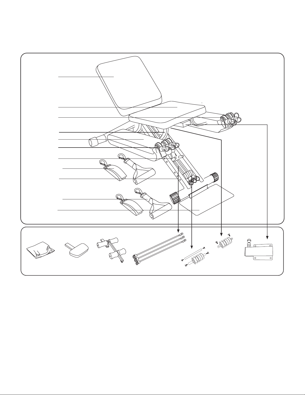
1. Power Pod Seat (Settings 1 – 5)
2. Seat (Settings A – E)
3. Spring Lock (Settings 1-5; A-E)
4. Seat Adjustment Holes
5. Power Pod (x2)
6. Resistance Band (with O-Ring & Stopper)
(3x per Power Pod)
7. Swivel Pulley (3x per side)
8. Stabilizer Bracket
9. Foot Plate
10. Handle & Clip (x2)
11. Ankle Cuff & Clip (x2)
OPTIONAL:
12. Cover
13. Head Rest*
14. Leg Extender*
15. Black Resistance Band
(with O-Ring & Stopper) (x3)**
16. 2 sets of Pulley (x3)
1 Slotted Axel
1 Axel
Retainer Pin (x1)**
17. Receptor Tube
C. Total Flex™ L Main Components
2
1
8
6
5
7
3
4
10
11
9
OPTIONAL:
MAIN UNIT:
12 13 14 15 16 17
*Need Receptor Tube (#17) for both these optional items
** Included with the Leg Extender package
3

D. Assembling the Total Flex™ L
The Total Flex™ L comes almost fully assembled with the exception of one Power
Pod that requires attachment to the side of the Power Pod Seat.
Power Pod Assembly
1. Please follow the steps under Section E in order to fully open up your Total Flex™ L.
Begin the assembly of the Power Pod after step 5 in Section E.
2. Align the curved brackets of the Power Pod with the two holes in the square tube
underneath the Power Pod Seat. See 1 below.
3. Use the 2 bolts with spring washers and the Allen wrench provided with the unit to
securely fasten the brackets to the square tubing. See 2 & 3 below.
Note: If you have purchased the Leg Extender (available as an optional item),
additional assembly is required – see below.
Receptor Tube Assembly (Optional Item)
To assemble the Receptor Tube, fit the following parts to the Total Flex™ L:
1. With the Total Flex™ L in the open position (see Section E below: Setting up the
Total Flex™ L on page 7), adjust the Power Pod Seat to setting 5.
2. Hold the Receptor Tube (see 2 below) and align with the four holes
on the underside of the Power Pod Seat (see 3 below). Use the 4 bolts and the
Allen wrench provided with the unit to securely fasten the Receptor Tube to the
Power Pod Seat (see 4 below).
1 2 3
1 2 3 4
4

Leg Extender Assembly (Optional Item)
To use the Leg Extender, fit the following parts to the Total Flex™ L:
1. Place the Retainer Pin between the Support Legs that are underneath the Power
Pod Seat 1 - 5. Align with the two holes and fasten the screws with the Allen
wrench provided (see 1 & 2 below).
2. Lay the three Black Resistance Bands over the Retainer Pin (see below).
3. Place the Pulley Axle (with Pulleys) between the Support Legs that are
underneath the Power Pod Seat 1 - 5. Align with the 2 holes and fasten the screws
with the Allen wrench provided (see 6 below).
4. Place the Slotted Pulley Axle (with Pulleys) into the brackets (located
below the Carry Handle). Align the axel holes with the holes in the bracket and
then fasten the axle to the brackets by tightening the 2 screws in with the screw
driver provided (see below).
1 2 3
4 5 6
7 8 9
5

7. Loop the 3 Black Resistance Bands over the Slotted Axle with 3 Pulley Wheels
(see 10 below).
8. Hook Resistance Bands onto Resistance Band Hooks (see 11 above).
Important: Before hooking the Bands, ensure that they are underneath the
Stabilizer Bracket (not over it - see 10 above). Also, ensure that the Bands are not
crossed (see 12 above).
9. Assemble the Leg Extender by inserting the Upper and Lower Roller Pipes into
the Leg Extender holes. Then slide the corresponding Upper and Lower Foam
Rollers over the respective Roller Pipes.
Important: The larger Foam Roller must be fitted to the longer Upper Roller Pipe.
Stabilizer Bracket
Upper
Lower
Hook
10 11 12
6

E. Setting Up the Total Flex™ L
Opening the Total Flex™ L
To open the Total Flex™ L (see 1 to 6 below), place the Total Flex™ L on a level
surface (1), remove Cover (optional item) (2), hold the Carry Handle with one hand
(3), move the Support Leg with the roller wheels (the leg with no Power Pods)
sideways (4) until it is fully opened (5) and adjust the Seat (6).
1 2 3
4 5 6
7

Insert the Foot Plate
Hold Foot Plate at a slight angle and then fully insert the “lip section” of the Foot
Plate into the Cross Pipe slot (i.e. the Pipe attached to the Power Pod Seat). Lower
the Foot Plate to the floor (see below).
Important: Make sure the Foot Plate is securely located into the slot.
Adjusting the Seats
1. To correctly align the body for exercising, the two seats must be adjusted for each
exercise as indicated on the Exercise Chart.
2. The seat positions are indicated on the Support Legs. For the Power Pod Seat,
settings are shown in numbers (1, 2, 3, 4 & 5). For the other Seat, settings are
indicated by letters (A, B, C, D & E).
WARNING: MAKE SURE SPRING PIN IS LOCKED IN PLACE BEFORE
BEGINNING YOUR EXERCISES.
3. For some of the exercises
there are 2 suggested seat
positions e.g. 3 & D or 2 & E.
The first would be more suitable
if you are male and/or tall; the
second, if you are female and/or
short.
Experiment and choose a
setting that will enable you,
at the start of the exercise, to
hold the Handles with slightly
bent arms and with the
Resistance Bands starting to
engage (beginning to stretch).
1 2 3
8

4. To adjust the seat position for each exercise, place one hand underneath the seat
(see 4a) and with the other hand, squeeze the Spring Lock together (see 4b), lift
or lower the seat(s) to the desired position, then release the Spring Lock.
WARNING: CRUSH HAZARD, KEEP HANDS CLEAR DURING FOLDING.
Important: Make sure that the pins at each side of the Spring Lock are securely en-
gaged in the Receptor Holes along the Leg Support (see 4c).
Seat Position Example
Exercise No. 4: Front Raise
Seat Settings: E & 2
Seat Position Example
Exercise No. 12: Chest Press
Seat Settings: C & 4
E
C
4a 4b 4c
4
2
9

F. Use of Attachments
The Handles and the Ankle Cuffs connect to the “O-Rings” at the ends of the
Resistance Bands (housed in the Power Pods - see page 11 or connect to the
Support Legs – see Leg Extender on page 11)
1. Power Pods
• Each Power Pod holds 3 Resistance Bands, varying in resistance (“weight”): Grey (low
resistance), Black (medium resistance) and Red (heavy resistance) (see 1 below).
• Each Resistance Band is fitted with an O-Ring. By clipping the Handles or Ankle
Cuff onto one or more of the O-Rings (see 1, 2 & 3 on page 11), the level of
exercise resistance can be varied - see Resistance Chart on Exercise Chart.
• When moving the Power Pod Seat (with settings: 1,2,3,4 & 5), the Power Pods
(attached to the seat) move in harmony, allowing the resistance to become
suitably aligned to the muscle(s) to be exercised.
Setting Up Your Workout Area
Make sure that you have enough space around your Total Flex™ L machine. The
following diagrams demonstrate the ‘training area’ (Figure 1a & 1b) as well as the
minimal ‘free area’ (Figures 2a & 2b) that should be available around you while you
are working out on this unit.
2a 2b
MINIMUM
MINIMUMMINIMUM
MINIMUM MINIMUM
1a 1b
10

2. Handles
• Each Handle is fitted with a metal clip to clip onto one or more of the O-Rings
attached to the end of each Resistance Band(s) (see 1a below).
1. After clipping the Handles onto the O-Rings, it is convenient to place
them onto the Power Pods for ease of use (see 1b below).
Important: Connect equal resistance to the right and left Handle(s) (see 1c above).
2. When exercising with the Seat in position D or E, engage resistance,
lean slightly forward and take hold of the handles with palms facing
downwards (see 2a). Then sit back to exercise (see 2b).
1 2 3
1a 1b 1c
2a 2b
Important: Do not sit or stand on the Power Pods
11

3a 3b
3. When performing abdominal exercises, the Handles can be held next to
the chest (see 3a) or above the shoulders (see 3b) (more difficult).
4. When lying in the “Bench Position” (setting B & 2), especially if you are
a female and/ or short, it may be more comfortable to lie with your feet off
the floor.
5. With the seats in the “Bench Position”, lay Handles down on the Power
Pods. Lie down, reach back and grab Handles with palms facing down
Then commence exercise.
12

3. Ankle Cuffs
• Secure the Ankle Cuff by looping it around the ankle, thread the end
through the metal bracket and bond the hook & loop tape together
(see 1 & 2 below).
• Clip the Ankle Cuff onto the O-Ring of one or more Resistance Bands
(see 3 below).
4. Foot Plate
• The Foot Plate is used for performing a number
of exercises in a standing position.
Important: Make sure that one or both feet are firmly
and fully placed on the Foot Plate when performing
exercises in the stranding position. Do not step off
the Foot Plate while exercising and when
engaging/disengaging the O-Rings to/from the
Handle(s) or Ankle Cuff(s).
5. Head Rest (Optional Item)
• The Head Rest is used for supporting the head
and neck whilst exercising facing upwards.
• Attach the Head Rest by pulling the Lock Pin on
the underside of the Power Pod Seat and insert
the Head Rest Tube into the Receptor Tube.
1 2 3
13

• The Head Rest has 4 settings to accommodate various body types. Engage
the setting suitable for your body type.
Important: Check that the Lock Pin engages fully when released.
6. Leg Extender (Optional Item)
The Leg Extender is an attachment for exercising the legs.
Note: Before using the Leg Extender, make sure that the Receptor Tube Assembly
is attached to the underside of the Power Pod Seat (see D – Leg Extender Assembly
on page 4).
Important: When attaching or detaching the Leg Extender, ensure that the
Resistance Bands are disengaged (unhooked) from the Leg Extender Hook.
• Connecting the Leg Extender to the Power Pod Seat.
Important: When using the Leg Extender, adjust the Seat (with Receptor Assembly)
to setting 3 – this is the only setting that must be used (see 6a below).
- Attach the Leg Extender by pulling the Lock Pin on the underside of the
Power Pod Seat and insert the Attachment Tube into the Receptor Tube
(see 6b below).
- The Leg Extender has 2 settings to accommodate various leg lengths.
Engage the setting suitable for your legs (see 6c below).
Important: Check that the Lock Pin engages fully when released.
Setting 3
6a 6b 6c
Lock Pin
14

• Adjustment of Foam Roller
Note: The position of the bottom Foam Roller
must be adjusted according to leg length.
To adjust:
- Pull off the Foam Roller from one side
of the Roller Pipe and remove the Pipe
from the Extender Tube (see 1).
- There are 4 holes. Select one that
positions the Foam Roller on the shin,
just above the top of the feet (see 2).
- Push back the Foam Roller over the
Roller Pipe.
• Engaging Resistance
- There are three red Resistance Bands
of equal resistance (‘weight’) fitted
between the Support Legs.
- By hooking one or more of the
O-Rings at the ends of the Resistance
Bands onto the Hook at the bottom of
the Extender Tube, the level of exercise
resistance can be varied - see Resistance
Chart on Exercise Chart. (see 3).
• Positioning for Exercising
1. Sit sideways on the Power Pod Seat.
2. Swing legs to front and over the top Foam Rollers.
3. Place feet underneath the bottom Foam Rollers.
4. Lean backwards against the Seat.
5. Start exercising by extending both legs forward.
1 2 3 4 5
1
2
3
15

To exercise means that the muscles of your body must move against (or overcome) a
force - called resistance, or “weight”
• The human body contains a large number of muscles. The exercises shown
on the Exercise Chart are designed to work the different muscles. As muscles
differ in strength, the resistance to be engaged when performing the different
exercises must be varied to match the strength of the particular muscle(s)
being exercised.
• Based on the principle of progressive overload, as you become fitter and as the
strength and endurance of your muscles improve, you must gradually increase
the resistance applied during each exercise in order to continue making
improvements in your fitness level.
• Exercise resistance for the Total Flex™ L is provided by two sources:
- Power Pods: Each Power Pod carries a set of 3 Resistance Bands
(varying in resistance or “weight”). By clipping the Handles or Ankle
Cuffs to one or more of the Resistance Bands, different levels of
exercise resistance can be obtained.
- Leg Extender: There are 3 red Resistance Bands (of equal resistance)
connected to the Support Legs underneath the Seats.
By connecting one or more of the Resistance Bands to the Leg
Extender, different levels of resistance can be obtained.
• Adjust the seats to positions 1 & A.
• Remove the Foot Plate.
• Place one foot next to the slotted pipe.
Then slowly lift the Carry Handle, allowing
the Support Leg fitted with Roller Wheels to
roll towards the other Support Leg.
• Important: For stability purposes, do not
store the unit as shown in image A, it is
recommended to store it as shown in image B.
• Place the Cover (optional item) over the
Total Flex™ L unit.
G. Exercise Resistance
H. Storing the Total Flex™ L
G. Exercise Resistance
A B
16

• To move the Total Flex™ L:
Move the machine by using the Carry Handle
General Maintenance
• The Total Flex™ L is for indoor use.
• Inspect the Total Flex™ L each time you
exercise and check for any loose parts
that may need to be tightened due to
wear and tear.
• If any of the Pulleys should squeak,
use a silicon-based lubricant to spray
onto the Pulley Shaft (see 1).
Note: Do not spray directly onto the
Pulley Wheel.
• If the Spring Pin becomes stiff and/or
the Seat becomes difficult to move up
or down, lubricate the Spring Pins
and/or inside of the support leg
channels with a silicon-based spray (see 2).
• Wipe away any excess lubrication.
I. Maintaining the Total Flex™ L
Warning: Exercise caution when lifting the machine
to avoid back injury.
1
2
17

Replacing Resistance Bands
• Removing a Damaged/Worn Resistance Band.
Important: Only remove and replace 1 Resistance Band at a time before
removing and replacing other Resistance Bands.
To replace worn or damaged Resistance Bands, proceed as follows:
3 4 5
1. With the Total Flex™ L in the open position,
adjust the Power Pod Seat to setting 5 (see 1).
2. Using the screwdriver provided, unscrew the 6 screws
holding the two Power Pod Covers together.
Note: Unscrew the middle 2 screws last
(see 2 & 3).
3. Unhook one Resistance Band from the Pod Hook
(see 4).
4. Remove the worn/damage Resistance Band by
pulling it out through the Swivel Pulley Bracket
(see 5).
1
2
18
Table of contents
Popular Fitness Equipment manuals by other brands

versa climber
versa climber TS Assembly manual

York Fitness
York Fitness Mega Max 3001 instructions

Samsara Fitness
Samsara Fitness TRUEFORM RUNNER owner's manual

Vectra Fitness
Vectra Fitness VX-DC owner's manual

BLK BOX
BLK BOX 21-0112-0J Owner's manual & quick start guide

Precor
Precor AMT12 base Service manual