Generally, the finer and cleaner the cut edge
should be the smaller the pendulum step
selected should be or switch off
action. For the working of thin material such as
sheet metal, switch off the pendulum action(Step
0). In hard material such as steel, work with small
pendulum action. In materials such as soft wood
and cutting in the direction of the grain, the large
pendulum action can be used.
Pendulum Setting:
Step 0: No pendulum action
Material: rubber, ceramic, aluminium, steel
Step 1: Small pendulum action
Material: plastic, wood, aluminium
Step 2: Medium pendulum action
Material: wood
Step 3: Large pendulum action
Material: wood
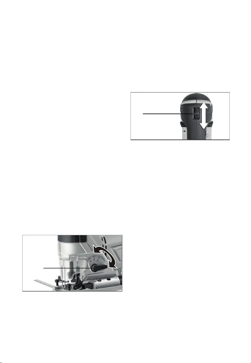
the pendulum
saw blade is lifted off the material which
facilitates sawdust ejection, reduces heat
generated by friction and increases the service
life of the saw blade. At the same time the
reduction of the necessary advancing force
makes fatigue-free working possible. The
pendulum action switch makes possible the
adjustment of the pendulum action in four steps.
The can take place with the machine
running:
switching
Pendulum Action Switch Adjustment
(see Dia 6)
The saw blade pendulum action, adjustable in
four steps, makes possible the optimum
adaptation of saw advancing(cutting speed),
cutting performance and cut appearance of the
material. For each downward movement, the
Stroke Rate Selection(see Dia 7)
With the thumbwheel, the required stroke rate
can be selected ( also while running).
MIN-2 = Low stroke rate
3-4 = Medium stroke rate
5-MAX = High stroke rate
The stroke rate required depends upon the
material and the working conditions: fast enough
to make reasonable progress, but slow enough
to keep a clean cut and to avoid straining the
machine. Generally, finer saw blades use a
higher speed, coarser blades use a slower
speed. After working for longer periods at low
stroke rate allow the machine to cool by running
it at maximum stroke rate and no load for
approx 3 minutes.
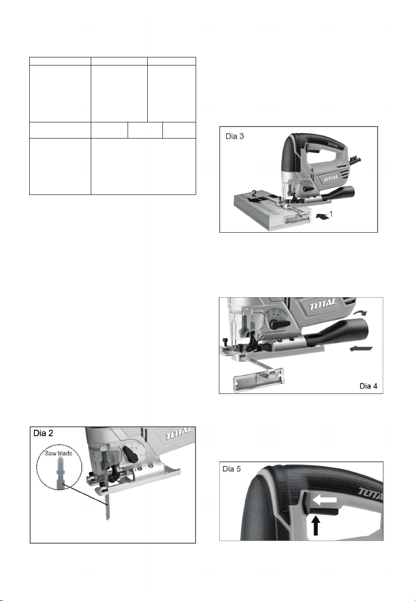
Using The Pendulum Jig saw
Before using the saw and connecting the mains
cable make sure the trigger switch is in the off
position. Press the trigger switch and wait until
blade has reached maximum speed. Place the
front of the baseplate on the workpiece and line
up the cutting line with the line you wish to cut.
Push slowly forward. Keep the baseplate flat
against the workpiece.
Cutting Metal
An appropriate cutting agent(such as light
oil, small amounts of soapy water, etc) should
always be used. If there is no available liquid
cutting agent, grease can be applied to the
back surface of the material to be cut.
Cutting Grooves/Window Holes
(see Dia 8)
For wood: Align the blade direction with the
grain of the wood. Then position the rounded
part at the front of the base plate on surface to
be cut, slowly lower the saw into material at
chosen point of entry. Lower the saw in a
pivoting action until blade has cut through to
other side, do not move saw along intended cut
line until the blade has cut through and base
plate is laying flat on material.
For other materials: In materials other than
wood when cutting window holes, first use a
drill or similar tool to drill a hole from which initial
cutting will begin.
Action switch
in step "0"
Dia 6
Dia 7
Selection
thumbwheel
in "1" position