Touch Dynamic QK10 All-in-One User manual

USER MANUAL
VERSION 1.3 December 2015
QK10 All-in-One

ii
Copyright 2015
All Rights Reserved
Manual Version 1.3
Part Number:
The information contained in this document is subject to change without notice.
We make no warranty of any kind with regard to this material, including, but not limited
to, the implied warranties of merchantability and fitness for a particular purpose.
We shall not be liable for errors contained herein or for incidental or consequential
damages in connection with the furnishing, performance, or use of this material.
This document contains proprietary information that is protected by copyright. All rights
are reserved. No part of this document may be photocopied, reproduced or translated
to another language without the prior written consent of the manufacturer.
TRADEMARK
Intel®, Pentium® and MMX are registered trademarks of Intel® Corporation.
Microsoft® and Windows® are registered trademarks of Microsoft Corporation.
Other trademarks mentioned herein are the property of their respective owners.
Safety
IMPORTANT SAFETY INSTRUCTIONS
1. To disconnect the machine from the electrical power supply, turn off the power switch
and remove the power cord plug from the wall socket. The wall socket must be easily
accessible and in close proximity to the machine.
2. Read these instructions carefully. Save these instructions for future reference.
3. Follow all warnings and instructions marked on the product.
4. Do not use this product near water.
5. Do not place this product on an unstable cart, stand, or table. The product may fall,
causing serious damage to the product.
6. Slots and openings in the cabinet and the back or bottom are provided for ventilation
to ensure reliable operation of the product and to protect it from overheating. These
openings must not be blocked or covered. The openings should never be blocked by
placing the product on a bed, sofa, rug, or other similar surface. This product should
never be placed near or over a radiator or heat register or in a built-in installation
unless proper ventilation is provided.
7. This product should be operated from the type of power indicated on the marking label.
If you are not sure of the type of power available, consult your dealer or local power
company.
8. Do not allow anything to rest on the power cord. Do not locate this product where
persons will walk on the cord.
9. Never push objects of any kind into this product through cabinet slots as they may
touch dangerous voltage points or short out parts that could result in a re or electric
shock. Never spill liquid of any kind on the product.

iii
Sécurité
INSTRUCTIONS IMPORTANTES RELATIVES À LA SECURITE
1. Pour débrancher la machine de l’alimentation électrique, éteignez l’interrupteur
d’alimentation et retirez le cordon d’alimentation de la prise murale. La prise murale
doit être facilement accessible et à proximité de la machine.
2. Lisez attentivement ces instructions. Conservez ces instructions pour une référence
future.
3. Suivez tous les avertissements et les instructions indiquées sur le produit.
4. Ne pas utiliser ce produit à proximité de l’eau.
5. Ne pas placer ce produit sur un chariot, un support ou une table. Le produit peut
tomber,causant de graves dommages à l’appareil.
6. Les fentes et les ouvertures dans le boîtier, l’arrière ou le fond sont prévues pour
la ventilation an d’assurer un fonctionnement able du produit et le protéger de la
surchauffe. Ces ouvertures ne doivent pas être obstruées ou couvertes. Les ouvertures
ne doivent jamais être bloquées en plaçant l’appareil sur un lit, un canapé, un tapis
ou autre surface similaire. Ce produit ne doit jamais être placé : à proximité ou sur un
radiateur, sur un registre de chaleur ou dans une installation intégrée à moins qu’une
ventilation adéquate soit prévue.
7. Ce produit doit être utilisé avec le type d’alimentation indiqué sur l’étiquette.Si
vous n’êtes pas sûr du type d’alimentation disponible, consultez votre revendeur ou
représentant local de l’entreprise.
8. Ne laissez rien reposer sur le cordon d’alimentation. Ne placez pas ce produit là oùdes
personnes peuvent marcher sur le cordon.
9. N’introduisez jamais d’objets d’aucune sorte dans ce produit à travers les fentes du
coffret car ils pourraient entrer en contact avec des points sous tension dangereux ou
court-circuiter des pièces. Ne renversez jamais de liquide d’aucune sorte sur le produit.
CE MARK
This device complies with the requirements of the EEC directive 2004/108/EC with
regard to “Electromagnetic compatibility” and 2006/95/EC “Low Voltage Directive”.
FCC
This device complies with part 15 of the FCC rules. Operation is subject to the following
two conditions:
(1) This device may not cause harmful interference.
(2) This device must accept any interference received, including interference that may
cause undesired operation.

iv
CAUTION ON LITHIUM BATTERIES
There is a danger of explosion if the battery is replaced incorrectly. Replace only
with the same or equivalent type recommended by the manufacturer. Discard used
batteries according to the manufacturer’s instructions.
Battery Caution
Risk of explosion if battery is replaced by an incorrectly type. Dispose of used battery
according to the local disposal instructions.
Safety Caution
Note: To comply with IEC60950-1 Clause 2.5 (limited power sources, L.P.S) related
legislation, peripherals shall be 4.7.3.2 “Materials for re enclosure” compliant.
4.7.3.2 Materials for re enclosures
For MOVABLE EQUIPMENT having a total mass not exceeding 18kg.the material of a
FIRE ENCLOSURE, in the thinnest signicant wall thickness used, shall be of V-1 CLASS
MATERIAL or shall pass the test of Clause A.2.
For MOVABLE EQUIPMENT having a total mass exceeding 18kg and for all STATIONARY
EQUIPMENT, the material of a FIRE ENCLOSURE, in the thinnest significant wall
thickness used, shall be of 5VB CLASS MATERIAL or shall pass the test of Clause A.1
AVERTISSEMENT SUR LES BATTERIES AU LITHIUM
Il y a un danger d’explosion si la batterie n’est pas remplacée correctement.
Remplacez-la uniquement par une batterie identique ou de type équivalent
recommandée par le fabricant.les batteries usagées doivent être mises au rebut
conformément aux instructions du fabricant.
Avertissement Batterie
Risque d’explosion si la batterie est remplacée par un élément incompatible.
Jetez les batteries usagées selon les instructions des dispositions locales .
Avertissement de sécurité
Remarque: Pour répondre à la norme IEC60950-1 alinéa 2.5 (sources d’énergie limitées,
LPS) liés la législation, les périphériques doivent être conforme 4.7.3.2 “Matériaux pour
enceinte coupe-feu»
4.7.3.2 “Matériaux pour équipements coupe-feu»
Pour les équipements mobiles ayant une masse totale n’excédant pas 18kg :
Les matériaux d’un équipement coupe-feu, dans l’épaisseur de paroi retenue la plus
signicativement mince, doivent être des matériels de CLASSE V-1 ou doivent passer le
test de l’article A.2.

v
Pour équipements mobiles ayant une masse totale supérieure à 18 kg et pour tous les
équipements FIXES :
Les matériaux d’un équipement coupe-feu dans l’épaisseur de paroi retenue la plus
signicativement mince, doivent être des matériels de CLASSE V-1, doivent être de
classe Matériel 5VB ou doivent passer le test de l’article A.1
LEGISLATION AND WEEE SYMBOL
2012/19/EU Waste Electrical and Electronic Equipment Directive on the treatment,
collection, recycling and disposal of electric and electronic devices and their
components.
The crossed dust bin symbol on the device means that it should not be disposed of
with other household wastes at the end of its working life. Instead, the device should
be taken to the waste collection centers for activation of the treatment, collection,
recycling and disposal procedure.
To prevent possible harm to the environment or human health from uncontrolled waste
disposal, please separate this from other types of wastes and recycle it responsibly to
promote the sustainable reuse of material resources.
Household users should contact either the retailer where they purchased this product,
or their local government ofce, for details of where and how they can take this item for
environmentally safe recycling.
Business users should contact their supplier and check the terms and conditions of
the purchase contract.
This product should not be mixed with other commercial wastes for disposal.

vi
Revision History
Changes to the original user manual are listed below:
Revision Description Date
1.0 • Initial release March 2013
1.1 • Ivy bridge board added November 2013
1.2 • J1900 board added May 2015
1.3 • Remove RJ11 port and relevant setting from
J1900 December 2015

vii
Table of Contents
1. Packing List.................................. 1
1-1. Standard Items................................................................1
1-2. Optional Items .................................................................2
2. System View.................................. 3
2-1. Front & Side View ............................................................3
2-2. Rear View.........................................................................3
2-3. I/O view............................................................................4
2-4. Dimensions.....................................................................5
3. System Assembly ......................... 6
3-1. Open the Chassis Cover..................................................6
3-2. RAM Module Replacement.............................................7
3-3. HDD Replacement ..........................................................8
4. Peripherals Installation ............... 9
4-1. MSR Installation..............................................................9
4-2. Cash Drawer Installation ...............................................10

viii
5. Specication................................ 12
6. Jumper Setting ............................ 15
6-1. D2550 Motherboard
...........................................................
15
6-1-1. Motherboard Layout........................................................15
6-1-2. Connectors & Functions .................................................16
6-1-3. Jumper Setting ................................................................ 17
6-2. Ivy Bridge Motherboard
...........................................................
20
6-2-1. Motherboard Layout........................................................20
6-2-2. Connectors & Functions .................................................21
6-2-3. Jumper Setting ................................................................22
6-3. J1900 Motherboard
..........................................................
25
6-3-1. Motherboard Layout........................................................25
6-3-2. Connectors & Functions .................................................26
6-3-3. Jumper Setting ................................................................ 27

ix
The page is intentionally left blank.

1
1. Packing List
1-1. Standard Items
a. System
b. Power adapter
c. Power cord
d. RJ45-DB9 cable (x2)
e. USB cable (x2)
f. Power extended cable
a. b.
c. d.
e. f.
Note: Power cord will be supplied differently according to various region or country.

2
1-2. Optional Items
MSR

3
2. System View
2-1. Front & Side View
2-2. Rear View
1
3
2
4
5
6
Item No. Description
1 Touch screen
2 Built-in web cam
3 Ventilation
4 MSR cable hole
Item No. Description
5 VESA mounting holes
6 Cable cover
7 Power button
7
4
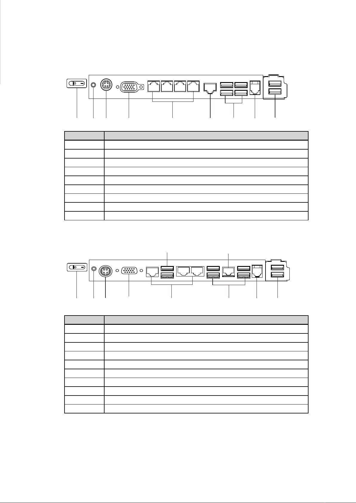
2-3. I/O view
Item No. Description
a 2nd power button
b Power button
c DC IN
dVGA
e COM port 1, 2, 3, 4 (from left to right)
f LAN
g USBx4 (two optional USB)
h Cash drawer
i USB (x2)
D2550 Motherboard
Ivy Bridge Motherboard
bcdefgh
ai
Item No. Description
a 2nd power button
b Power button
c DC IN
dVGA
e COM port 1, 2, 3 (from right to left)
f USB 2.0 (x4) (two optional USB)
g Cash drawer
h USB (x2)
i USB 3.0 (x2)
j LAN
b c defgh
a
ij

5
2-4. Dimensions
263mm
170mm
38mm
Item No. Description
a Power button
b DC Jack 19V
cVGA
d COM3
e USB2
f COM1~COM2(from right to left)
g USB 2.0 (x4) (two optional USB)
h LAN
i USB3/USB4
J1900 Motherboard
bcd f
g
h
aei

6
3. System Assembly
3-1. Open the Chassis Cover
The motherboard and RAM module can be replaced by opening the chassis
cover, which is located on the back side of the system. Please follow the steps
below to open the chassis cover.
1. Turn to the back side of the sys-
tem and loosen the screws (x2) to
release the cable cover first.
2. Loosen the screws (x4) to open
the back cover of the system.

7
3-2. RAM Module Replacement
To remove and replace the RAM module, please open the chassis cover firstly
as steps dscribed in chapter 3-1.
Removing a RAM module
1. Find the memory slot at the right side of the motherboard.
2. Flip the ejector clips outwards to remove the memory module from the memory
slot.
Installing a RAM moudle
3. Slide the memory module into the memory slot and press down until the
ejector clips snaps in place.

8
3-3. HDD Replacement
To remove and replace the HDD, please open the cable cover rstly as stpes dscribed
in chapter 3-1-1.
1. Loosen the screws(x2) to remove
the HDD bracket from the system
2. The HDD is secured by the bracket,
remove the screws(x2) to release
the bracket and replace the HDD.
9
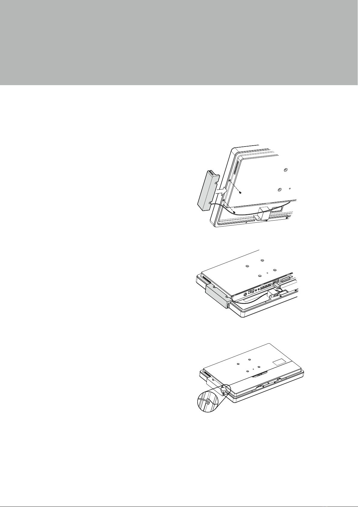
4. Peripherals Installation
4-1. MSR Installation
1. Insert MSR module in place and
fasten the screws (x2) on the back to
secure the module.
To install MSR, please open the cable cover rstly as steps described in chapter 3-1-1.
2. Connect MSR cable to the connector on
system side.
3. Close the cable cover and fasten
screws (x2). Make sure the MSR cable
is threaded through the MSR cable
hole on the system.
10
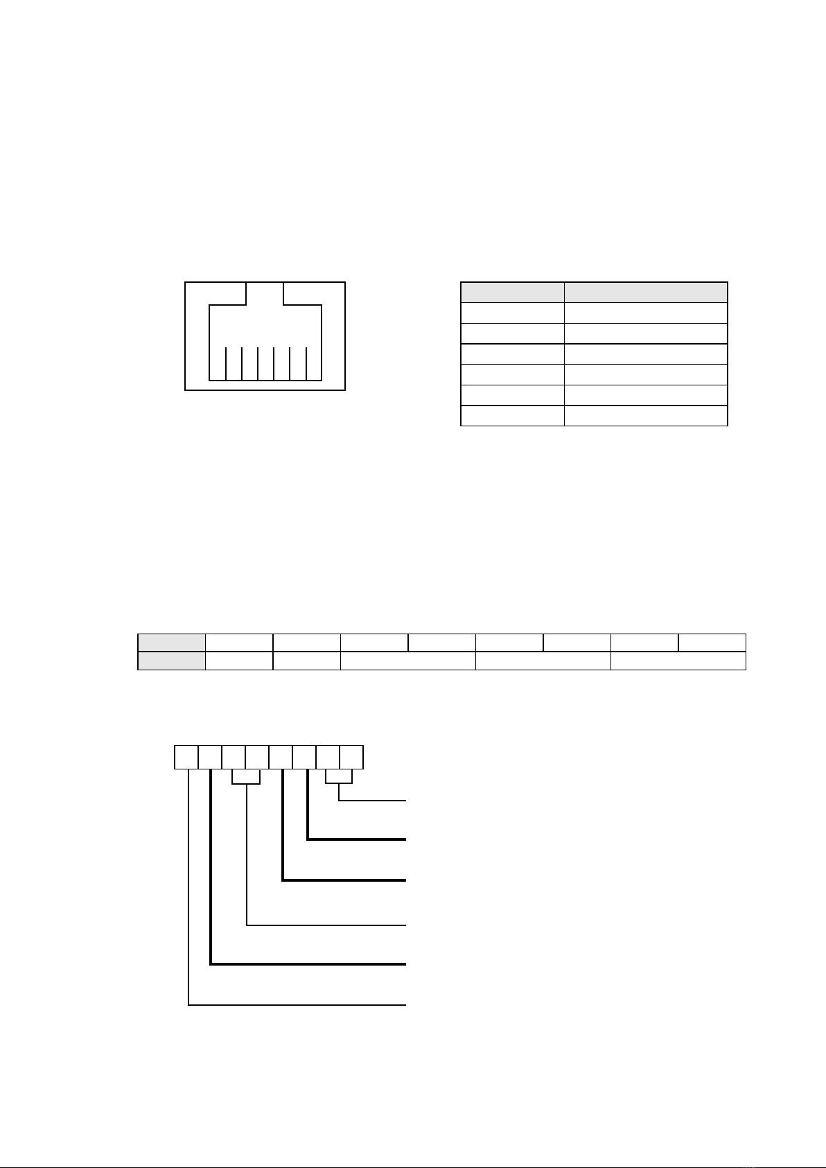
4-2. Cash Drawer Installation
You can install a cash drawer through the cash drawer port. Please verify the pin
assignment before installation.
Cash Drawer Pin Assignment
Pin Signal
1 GND
2 DOUT bit0
3 DIN bit0
4 12V / 19V
5 DOUT bit1
6 GND
1
6
Cash Drawer Controller Register
The Cash Drawer Controller use one I/O addresses to control the Cash Drawer.
Register Location: 48Ch
Attribute: Read / Write
Size: 8bit
BIT BIT7 BIT6 BIT5 BIT4 BIT3 BIT2 BIT1 BIT0
Attribute Reserved Read Reserved Write Reserved
76543210
XX X X X
Reserved
Cash Drawer “DOUT bit0” pin output control
Cash Drawer “DOUT bit1” pin output control
Reserved
Cash Drawer “DIN bit0” pin input status
Reserved
For D2550/Ivy Bridge Motherboard

11
Bit 7: Reserved
Bit 6: Cash Drawer “DIN bit0” pin input status.
= 1: the Cash Drawer closed or no Cash Drawer
= 0: the Cash Drawer opened
Bit 5: Reserved
Bit 4: Reserved
Bit 3: Cash Drawer “DOUT bit1” pin output control.
= 1: Opening the Cash Drawer
= 0: Allow close the Cash Drawer
Bit 2: Cash Drawer “DOUT bit0” pin output control.
= 1: Opening the Cash Drawer
= 0: Allow close the Cash Drawer
Bit 1: Reserved
Bit 0: Reserved
Note: Please follow the Cash Drawer control signal design to control the Cash Drawer.
Cash Drawer Control Command Example
Use Debug.EXE program under DOS or Windows98
Command Cash Drawer
O 48C 04 Opening
O 48C 00 Allow to close
►Set the I/O address 48Ch bit2 =1 for opening Cash Drawer by “DOUT bit0” pin
control.
►Set the I/O address 48Ch bit2 = 0 for allow close Cash Drawer.
Command Cash Drawer
I 48C Check status
►The I/O address 48Ch bit6 =1 mean the Cash Drawer is opened or not exist.
►The I/O address 48Ch bit6 =0 mean the Cash Drawer is closed.
This manual suits for next models
1
Table of contents
Other Touch Dynamic Industrial PC manuals


