Neousys Nuvo-6108GC Series User manual

Neousys Technology Inc.
Nuvo-6108GC Series
User Manual
Revision 1.3

Table of Contents
Table of Contents
Table of Contents...................................................................................................................2
Legal Information...................................................................................................................4
Contact Information...............................................................................................................5
Declaration of Conformity.....................................................................................................5
Copyright Notice....................................................................................................................6
Safety Precautions.................................................................................................................7
Hot Surface Warning..............................................................................................................7
Battery Warning......................................................................................................................7
Service and Maintenance ......................................................................................................8
ESD Precautions....................................................................................................................8
Restricted Access Location..................................................................................................8
About This Manual.................................................................................................................9
1Introduction
1.1 Nuvo-6108GC Specifications...................................................................................11
1.2 Nuvo-6108GC-IGN Specification.............................................................................13
1.3 Dimension.................................................................................................................15
1.3.1 I/O Panel View..................................................................................................15
1.3.2 Removable Side Panel View.............................................................................16
1.3.3 I/O Panel View with Damping Bracket Installed................................................17
1.3.4 Bottom View with Damping Bracket Installed....................................................18
2System Overview
2.1 Nuvo-6108GC Packing List......................................................................................19
2.1 Nuvo-6108GC-IGN Packing List..............................................................................19
2.2 External I/O ...............................................................................................................20
2.3.1 Reset Button.....................................................................................................22
2.3.2 Power Button ....................................................................................................23
2.3.3 4-pole 3.5mm Speaker-out/ Microphone-in Jack...............................................24
2.3.4 LED Indicators ..................................................................................................25
2.3.5 USB 3.0 Port.....................................................................................................26
2.3.6 GbE Port...........................................................................................................27
2.3.7 DVI Port............................................................................................................28
2.3.8 COM Port..........................................................................................................29
2.3.9 3-Pin Terminal Block for DC Input.....................................................................31
2.3.10 3-Pin Remote On/ Off .......................................................................................32
2.3.11 3-pin Terminal Block (DC/ Ignition Input)...........................................................33
2.4 Internal I/O Functions...............................................................................................34
2.4.1 Status LED Output & Remote On/ Off Control and Pin Definition.....................34
2.4.2 Dual DRAM SODIMM Slot................................................................................36
2.4.3 mini-PCIe Slot and Pin Definition......................................................................37
2.4.4 M.2 (B Key) and SIM Card Slot.........................................................................39
2.4.5 SATA Port 1.......................................................................................................41
2.4.6 SATA Ports 2, 3 and 4.......................................................................................42
2.4.7 Internal USB Port on Extension Board..............................................................43
2.4.8 PCIe 8-Pin and 6-Pin 12V VDC Power Connector............................................44
2.4.9 X16/ x8 PCI Express Slots................................................................................45
3System Installation
3.1 Disassembling the System......................................................................................47
3.2 Installing Internal Components...............................................................................53
3.2.1 CPU Installation Procedure...............................................................................53
3.2.2 DDR4 SO-DIMM Installation.............................................................................57
3.2.3 M.2 Module, SIM Card and Antennae Installation.............................................59
3.2.4 mini-PCIe Module andAntennae Installation....................................................61

Table of Contents
3
3.2.5 Installing HDD/ SSD to SATA Port 1..................................................................63
3.2.6 Installing HDD/ SSD to SATA Ports 2/ 3/ 4........................................................65
3.2.7 Installing External 2.5” HDD/ SSD (Nuvo-6108GC-IGN Only) ..........................67
3.2.8 PCI/ PCIe Add-on Card Installation...................................................................69
3.3 Installing the System Enclosure .............................................................................73
3.4 Anti-vibrate Grommet/ Mounting Bracket Installation...........................................76
3.5 Powering On the System .........................................................................................77
3.5.1 Powering On Using the Power Button...............................................................77
3.5.2 Powering On Using Wake-on-LAN....................................................................78
3.6Ignition Power Control (Nuvo-6180GC-IGN Only)..................................................80
3.6.1 Principles of Ignition Power Control..................................................................80
3.6.2 Additional Features of Ignition Power Control...................................................81
3.6.3 Wiring Ignition Signal........................................................................................82
3.6.4 Configure your Windows system.......................................................................83
3.6.5 Operation Modes of Ignition Power Control......................................................84
4System Configuration
4.1 BIOS Settings ...........................................................................................................87
4.1.1 COM1 & COM2 Configuration...........................................................................88
4.1.2 SATA Configuration...........................................................................................89
4.1.3 TPMAvailability.................................................................................................91
4.1.4 Auto Wake on S5..............................................................................................92
4.1.5 Power On After Power Failure Option...............................................................93
4.1.6 Power & Performance (CPU SKU Power Configuration)..................................94
4.1.7 Wake on LAN Option ........................................................................................95
4.1.8 Boot Menu ........................................................................................................96
4.1.9 Boot Type (Legacy/ UEFI).................................................................................98
4.1.10 Position New Boot Device...............................................................................100
4.1.11 Watchdog Timer for Booting............................................................................101
4.1.12 Legacy/ UEFI Boot Device..............................................................................102
4.2 AMT Configuration.................................................................................................103
4.3 RAID Configuration................................................................................................105
5OS Support and Driver Installation
5.1 Operating System Compatibility...........................................................................107
5.2 Driver Installation...................................................................................................108
5.2.1 Install Drivers Automatically............................................................................108
5.2.2 Install Drivers Manually...................................................................................109
5.3 Driver Installation for Watchdog Timer Control...................................................110
Appendix A Using WDT & DIO
WDT and DIO Library Installation.....................................................................................112
WDT Functions...................................................................................................................114
InitWDT................................................................................................................................114
SetWDT ...............................................................................................................................114
StartWDT............................................................................................................................. 115
ResetWDT ...........................................................................................................................115
StopWDT .............................................................................................................................115

Legal Information
Legal Information
All Neousys Technology Inc. products shall be subject to the latest Standard
Warranty Policy
Neousys Technology Inc. may modify, update or upgrade the software, firmware or
any accompanying user documentation without any prior notice. Neousys
Technology Inc. will provide access to these new software, firmware or
documentation releases from download sections of our website or through our
service partners.
Before installing any software, applications or components provided by a third party,
customer should ensure that they are compatible and interoperable with Neousys
Technology Inc. product by checking in advance with Neousys Technology Inc..
Customer is solely responsible for ensuring the compatibility and interoperability of
the third party’s products. Customer is further solely responsible for ensuring its
systems, software, and data are adequately backed up as a precaution against
possible failures, alternation, or loss.
For questions in regards to hardware/ software compatibility, customers should
contact Neousys Technology Inc. sales representative or technical support.
To the extent permitted by applicable laws, Neousys Technology Inc. shall NOT be
responsible for any interoperability or compatibility issues that may arise when (1)
products, software, or options not certified and supported; (2) configurations not
certified and supported are used; (3) parts intended for one system is installed in
another system of different make or model.

Contact Information/ Declaration of Conformity
Contact Information
Headquarters
(Taipei, Taiwan)
Neousys Technology Inc.
15F, No.868-3, Zhongzheng Rd., Zhonghe Dist., New Taipei City, 23586, Taiwan
Tel: +886-2-2223-6182 Fax: +886-2-2223-6183 Email, Website
Americas
(Illinois, USA)
Neousys Technology America Inc.
3384 CommercialAvenue, Northbrook, IL 60062, USA
Tel: +1-847-656-3298 Email, Website
China Neousys Technology (China) Ltd.
Room 612, Building 32, Guiping Road 680, Shanghai
Tel: +86-2161155366 Email, Website
Declaration of Conformity
FCC This equipment has been tested and found to comply with the limits for a Class
A digital device, pursuant to part 15 of the FCC Rules. These limits are
designed to provide reasonable protection against harmful interference when
the equipment is operated in a commercial environment. This equipment
generates, uses, and can radiate radio frequency energy and, if not installed
and used in accordance with the instruction manual, may cause harmful
interference to radio communications. Operation of this equipment in a
residential area is likely to cause harmful interference in which case the user will
be required to correct the interference at own expense.
CE The product(s) described in this manual complies with all applicable European
Union (CE) directives if it has a CE marking. For computer systems to remain
CE compliant, only CE-
compliant parts may be used. Maintaining CE
compliance also requires proper cable and cabling techniques.

Copyright Notice
Copyright Notice
All rights reserved. This publication may not be reproduced, transmitted,
transcribed, stored in a retrieval system, or translated into any language or
computer language, in any form or by any means, electronic, mechanical,
magnetic, optical, chemical, manual or otherwise, without the prior written
consent of Neousys Technology, Inc.
Disclaimer This manual is intended to be used as an informative guide only and is subject
to change without prior notice. It does not represent commitment from Neousys
Technology Inc. Neousys Technology Inc. shall not be liable for any direct,
indirect, special, incidental, or consequential damages arising from the use of
the product or documentation, nor for any infringement on third party rights.
Patents and
Trademarks
Neousys, the Neousys logo, Expansion Cassette, MezIOTM are registered
patents and trademarks of Neousys Technology, Inc.
Windows is a registered trademark of Microsoft Corporation.
Intel®, Core™ are registered trademarks of Intel Corporation
NVIDIA®, GeForce®are registered trademarks of NVIDIA Corporation
All other names, brands, products or services are trademarks or registered
trademarks of their respective owners.
Service and Maintenance/ ESD Precautions
Safety Precautions
Read these instructions carefully before you install, operate, or transport the system.
Install the system or DIN rail associated with, at a sturdy location
Install the power socket outlet near the system where it is easily accessible
Secure each system module(s) using its retaining screws
Place power cords and other connection cables away from foot traffic. Do not
place items over power cords and make sure they do not rest against data cables
Shutdown, disconnect all cables from the system and ground yourself before
touching internal modules
Ensure that the correct power range is being used before powering the device
Should a module fail, arrange for a replacement as soon as possible to minimize
down-time
By means of a power cord connected to a socket-outlet with earthing connection
This product is intended to be supplied by a Listed Power Adapter or DC power
source, rated 24Vdc, 16A, Tma 60 degree C and 5000m altitude during operation.
If further assistance is required, please contact Neousys Technology
If the system is not going to be used for a long time, disconnect it from mains
(power socket) to avoid transient over-voltage
Hot Surface Warning
HOT SURFACE. DO NOT
TOUCH. "ATTENTION: Surface chaude. Ne
pas toucher."
WARNING!
Components/ parts inside the
equipment may be hot to touch!
Please wait one-half hour after
switching off before handling parts.
Battery Warning
Batteries are at risk of exploding if incorrectly
installed
Do not attempt to recharge, force open, or heat the
battery
Replace the battery only with the same or equivalent
type recommended by the manufacturer

Table of Contents
8
Service and Maintenance
ONLY qualified personnel should service the system
Shutdown the system, disconnect the power cord and all other connections
before servicing the system
When replacing/ installing additional components (expansion card, memory
module, etc.), insert them as gently as possible while assuring proper connector
engagement
ESD Precautions
Handle add-on module, motherboard by their retention screws or the module’s
frame/ heat sink. Avoid touching the PCB circuit board or add-on module
connector pins
Use a grounded wrist strap and an anti-static work pad to discharge static
electricity when installing or maintaining the system
Avoid dust, debris, carpets, plastic, vinyl and styrofoam in your work area.
Do not remove any module or component from its anti-static bag before
installation
Restricted Access Location
The controller is intended for installation only in certain environments where both of
the following conditions apply:
Access can only be gained by QUALIFIED SERVICE PERSONNEL who have
been instructed on the reasons for restrictions applied to the location and any
precautions that shall be taken
Access is through the use of a TOOL, lock and key, or other means of security,
and is controlled by the authority responsible for the location

About This Manual
About This Manual
This guide introduces Neousys Nuvo-6108GC series system. An industrial grade
GPU computer integrating high-end NVIDIA® graphics card with Intel® Xeon® E3 v5
or 6th Gen Core™ processors.
The guide also demonstrates the system’s basic installation procedures.
Revision History
Version Date Description
1.0 Mar. 2018 Initial release
1.1 Dec. 2019 Specification update
1.2 Apr. 2020 Added Nuvo-6108GC-IGN
1.3 Apr. 2020 Update mini-PCIe specifications

Nuvo-6108GC/ Nuvo-6108GC-IGN
10
1 Introduction
The Neousys Nuvo-6108GC is the world’s first industrial-grade GPU computer
integrating NVIDIA® graphics card and an Intel Xeon processor.
The perfect replacement for 19” rackmount IPC systems, Nuvo-6108GC is powered
by Intel® Xeon® E3 v5 or 6th Gen Core™ processor with C236 chipset, supports up
to 32GB of ECC/ non-ECC DDR4 memory and has rich I/O ports such as Gigabit
Ethernet, USB3.0, video ports and serial ports. In addition to the x16 PCIe port for
GPU installation, there are two x8 PCIe expansion slots for additional devices or
other application means.
In order to sustain high GPU performance in industrial environments, Nuvo-6108GC
features patented cold air intake design to effectively dissipate heat generated by the
graphics card. The unique design guarantees operation at 60℃with 100% GPU
loading and ensures Nuvo-6108GC’s reliability for demanding field use. In addition,
Nuvo-6108GC comes with patented shock/ vibration absorption mounting brackets
to ensure the system’s smooth operation under harsh environments.
“GPU computing is a popular emerging technology and has been a hot topic in the
last five years. Nuvo-6108GC is Neousys’ response to advanced GPU-accelerated
computing and is applicable to applications such as artificial intelligence, virtual
reality, autonomous driving and CUDA computing.

Nuvo-6108GC/ Nuvo-6108GC-IGN
11
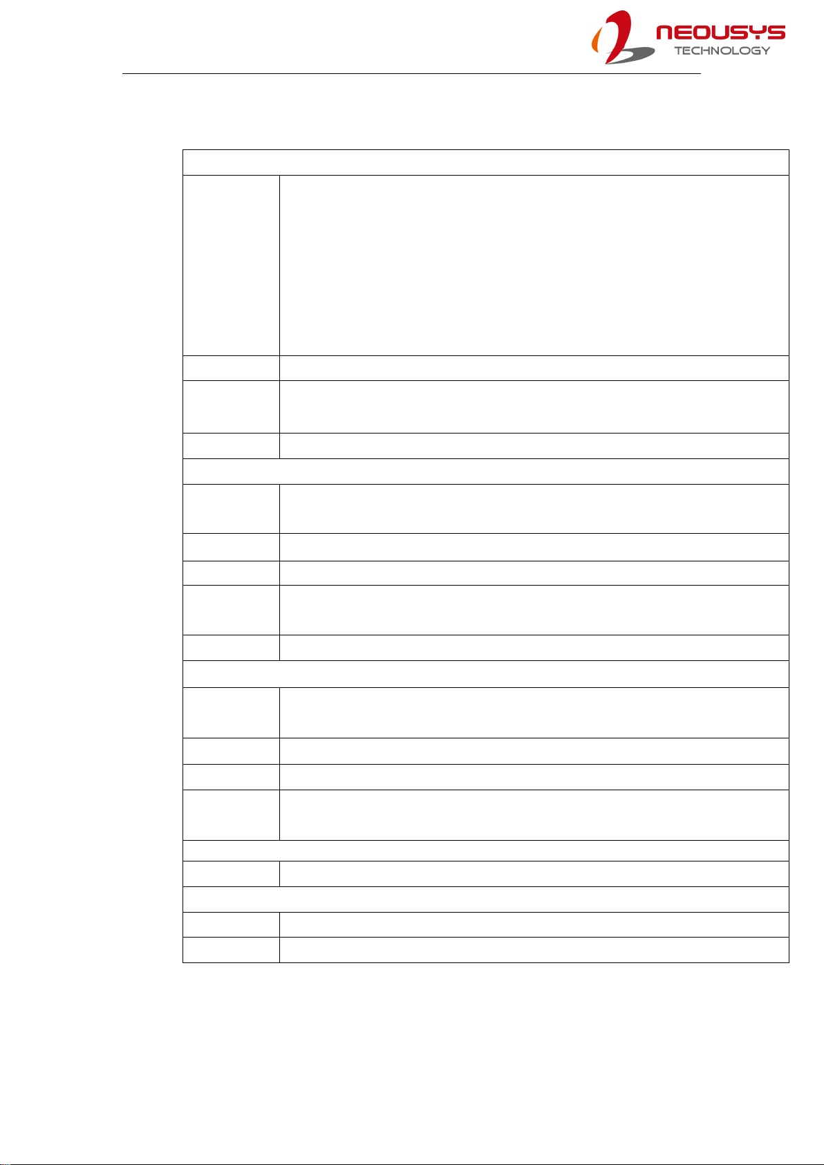
1.1 Nuvo-6108GC Specifications
System Core
Processor
Supports Intel® Xeon® E5 v3 and 6th-Gen Core™ LGA1151 CPU
- Intel® Xeon® Processor E3-1275 v5 (8M Cache, 3.6/4.0 GHz)*
- Intel® Xeon® Processor E3-1268L v5 (8M Cache, 2.4/3.4 GHz)
- Intel® Core™ i7-6700 (8M Cache, 3.4/4.0 GHz)*
- Intel® Core™ i5-6500 (6M Cache, 3.2/3.6 GHz)*
- Intel® Core™ i7-6700TE (8M Cache, 2.4/ 3.4 GHz)
- Intel® Core™ i7-6500TE (6M Cache, 2.3/3.3 GHz)
Chipset Intel® C236 platform controller hub
Graphics Independent GPU (up to 250W TDP) via x16 PEG port or i
ntegrated Intel® HD 530
graphics
Memory Up to 32 GB ECC/ non-ECC DDR4-2133
I/O Interface
Ethernet 1x Gigabit Ethernet port by Intel I219-LM
1x Gigabit Ethernet port by Intel I210-IT
Video Port 2x DVI-D connectors supporting 1920x1200 resolution
Serial Port 2x Software-programmable RS-232/422/485 ports
USB 4x USB 3.0 ports
1x USB 2.0 port (internal daughterboard)
Audio 1x 3.5mm jack for speaker-output and microphone-input
Expansion Bus
PCI Express 1x PCIe x16 slot @ Gen3, 16-lanes PCIE signals for GPU
2x PCIe x8 slot @ Gen3, 4-lanes PCIE signals
M.2 1x M.2 B key socket for 3G/ 4G options with SIM socket
mini-PCIe 1x full-size mini-PCI Express socket
Remote Ctrl. &
Status Output 1x 2x6-pin 2.0mm pin-header connector for remote on/off control and status LED output
Storage Interface
SATA HDD 4x Internal SATA ports for 2.5” HDD/SSD installation, supporting RAID 0/ 1/ 5/ 10
Power Supply
DC Input 1x 3-pin pluggable terminal block for 24VDC input */**
Remote ctrl. 1x 3-pin pluggable terminal block for remote on/off control

Nuvo-6108GC/ Nuvo-6108GC-IGN
12
Max. Power
Consumption
With E3-1268L v5: 50.16W@24VDC
With i7-6700TE (35W TDP): 53.76W@24VDC
With i5-6500TE (35W TDP): 35.04W@24VDC
With i3-6500TE (Max. TDP): 58.08W@24VDC
Mechanical
Dimension 164 mm (W) x 360 mm (D) x 174 mm (H)
Weight Approx. 4.7 kg (including CPU, memory, HDD)
Mounting Damping bracket (Standard)
Environmental
Temperature
Storage: -40°C ~ 85°C
with 35W CPU and dual NVIDIA® 250W GPU
-25°C ~ 60°C ***
with >= 65W CPU and dual NVIDIA® 250W GPU
-25°C ~ 60°C ***/ **** (configured as 35W TDP mode)
-25°C ~ 50°C ***/ **** (configured as 65W TDP mode)
Humidity 10%~90% , non-condensing
Vibration Operating, 1.0Grms, 5-500 Hz, 3 Axes (w/ GPU, fan, HDD and damping bracket installed,
according to IEC60068-2-64)
EMC CE/FCC Class A, according to EN 55022 & EN 55024
* When an NVIDIA® graphics card is installed, DC input should adopt 24V
** Max current for DC input is 16A (per PWR pin) and max power consumption for
the system is 384W
*** For 65W CPU operating at 65W mode, the highest operating temperature shall be
limited to 50°C and thermal throttling may occur when sustained full-loading applied.
Users can configure the CPU TDP in the BIOS to obtain higher operating
temperature
**** For sub-zero operating temperature, a wide temperature HDD or Solid State
Disk (SSD) is required
Nuvo-6108GC/ Nuvo-6108GC-IGN
13
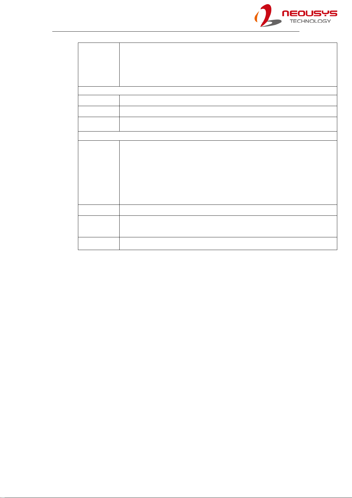
1.2 Nuvo-6108GC-IGN Specification
System Core
Processor
Supports Intel® Xeon® E5 v3 and 6th-Gen Core™ LGA1151 CPU
- Intel® Xeon® Processor E3-1275 v5 (8M Cache, 3.6/4.0 GHz)*
- Intel® Xeon® Processor E3-1268L v5 (8M Cache, 2.4/3.4 GHz)
- Intel® Core™ i7-6700 (8M Cache, 3.4/4.0 GHz)*
- Intel® Core™ i5-6500 (6M Cache, 3.2/3.6 GHz)*
- Intel® Core™ i7-6700TE (8M Cache, 2.4/ 3.4 GHz)
- Intel® Core™ i7-6500TE (6M Cache, 2.3/3.3 GHz)
Chipset Intel® C236 platform controller hub
Graphics Independent GPU (up to 250W TDP)
via x16 PEG port or integrated Intel® HD 530
graphics
Memory Up to 32 GB ECC/ non-ECC DDR4-2133
I/O Interface
Ethernet 1x Gigabit Ethernet port by Intel I219-LM
1x Gigabit Ethernet port by Intel I210-IT
Video Port 2x DVI-D connectors supporting 1920x1200 resolution
Serial Port 2x Software-programmable RS-232/422/485 ports
USB 4x USB 3.0 ports
1x USB 2.0 port (internal daughterboard)
Audio 1x 3.5mm jack for speaker-output and microphone-input
Expansion Bus
PCI Express 1x PCIe x16 slot @ Gen3, 16-lanes PCIE signals for GPU
2x PCIe x8 slot @ Gen3, 4-lanes PCIE signals
M.2 1x M.2 B key socket for 3G/ 4G options with SIM socket
mini-PCIe 1x full-size mini-PCI Express socket
Remote Ctrl. &
Status Output 1x 2x6-pin 2.0mm pin-header connector for remote on/off control and status LED output
Storage Interface
SATA HDD 4x Internal SATA ports for 2.5” HDD/SSD installation, supporting RAID 0/ 1/ 5/ 10
Power Supply
DC Input 1x 3-pin pluggable terminal block for 24VDC input */**
1x 3-pin pluggable terminal block for 24V DC input (IGN/ GND/ V+) */**
Nuvo-6108GC/ Nuvo-6108GC-IGN
14
Max. Power
Consumption
With E3-1268L v5: 50.16W@24VDC
With i7-6700TE (35W TDP): 53.76W@24VDC
With i5-6500TE (35W TDP): 35.04W@24VDC
With i3-6500TE (Max. TDP): 58.08W@24VDC
Mechanical
Dimension 164 mm (W) x 360 mm (D) x 174 mm (H)
Weight Approx. 4.7 kg (including CPU, memory, HDD)
Mounting Damping bracket (Standard)
Environmental
Temperature
Storage: -40°C ~ 85°C
with 35W CPU and dual NVIDIA® 250W GPU
-25°C ~ 60°C ***
with >= 65W CPU and dual NVIDIA® 250W GPU
-25°C ~ 60°C ***/ **** (configured as 35W TDP mode)
-25°C ~ 50°C ***/ **** (configured as 65W TDP mode)
Humidity 10%~90% , non-condensing
Vibration Operating, 1.0Grms, 5-500 Hz, 3 Axes (w/ GPU, fan, HDD and damping bracket installed,
according to IEC60068-2-64)
EMC CE/FCC Class A, according to EN 55022 & EN 55024
* When an NVIDIA® graphics card is installed, DC input should adopt 24V
** Max current for DC input is 16A (per PWR pin) and max power consumption for
the system is 384W
*** For 65W CPU operating at 65W mode, the highest operating temperature shall be
limited to 50°C and thermal throttling may occur when sustained full-loading applied.
Users can configure the CPU TDP in the BIOS to obtain higher operating
temperature
**** For sub-zero operating temperature, a wide temperature HDD or Solid State
Disk (SSD) is required

Nuvo-6108GC/ Nuvo-6108GC-IGN
15
1.3 Dimension
NOTE
All measurements are in millimeters (mm).
1.3.1 I/O Panel View
Nuvo-6108GC
Nuvo-6108GC-IGN

Nuvo-6108GC/ Nuvo-6108GC-IGN
16
1.3.2 Removable Side Panel View
Nuvo-6108GC
Nuvo-6108GC-IGN

Nuvo-6108GC/ Nuvo-6108GC-IGN
17
1.3.3 I/O Panel View with Damping Bracket Installed
Nuvo-6108GC
Nuvo-6108GC-IGN

Nuvo-6108GC/ Nuvo-6108GC-IGN
18
1.3.4 Bottom View with Damping Bracket Installed
Nuvo-6108GC
Nuvo-6108GC-IGN

Nuvo-6108GC/ Nuvo-6108GC-IGN
19
2 System Overview
Upon receiving and unpacking your Nuvo-6108GC, please check immediately if the
package contains all the items listed in the following table. If any item(s) are missing
or damaged, please contact your local dealer or Neousys Technology.
2.1 Nuvo-6108GC Packing List
System
Pack Nuvo-6108GC Qty
1 Nuvo-6108GC
(If you ordered CPU/ RAM/ HDD, please verify these items) 1
2
Accessory box, which contains
SATA HDD/ SSD bracket
Neousys drivers & utilities DVD
Damping bracket for mobile deployment
Shock-absorbing grommet
3-pin power terminal block
Screw pack
1
2
2
8
1
1
2.1 Nuvo-6108GC-IGN Packing List
System
Pack Nuvo-6108GC-IGN Qty
1 Nuvo-6108GC-IGN
(If you ordered CPU/ RAM/ HDD, please verify these items) 1
2
Accessory box, which contains
SATA HDD/ SSD bracket
Neousys drivers & utilities DVD
Damping bracket for mobile deployment
Shock-absorbing grommet
3-pin power terminal block
Screw pack
1
2
2
8
1
1
Nuvo-6108GC/ Nuvo-6108GC-IGN
20
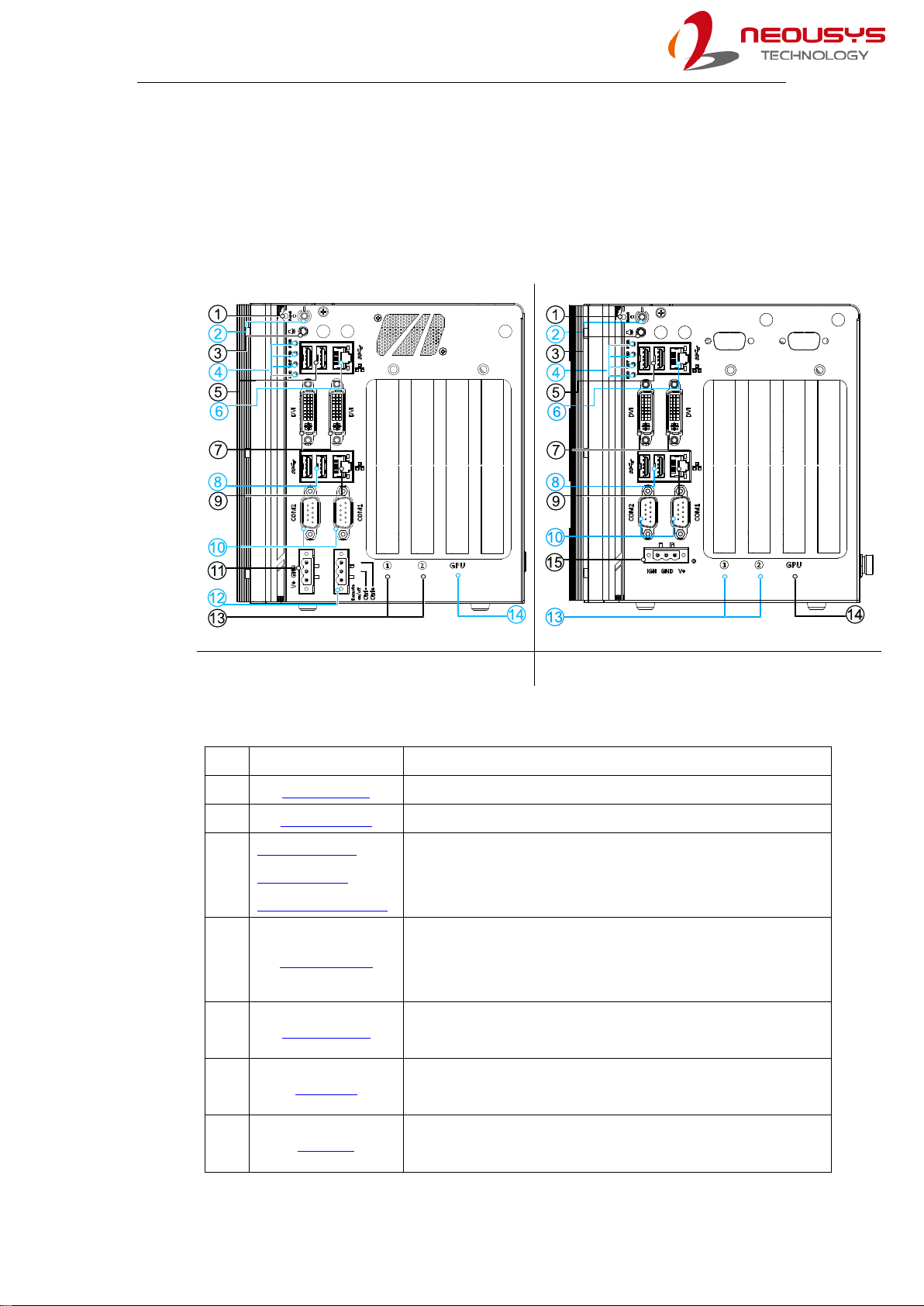
2.2 External I/O
The Nuvo-6108GC series I/O panel featuresdual gigabit Ethernet, four USB3.0, dual
DVI ports (off motherboard chipset), dual serial ports, 3-pin ignition and DC input
(Nuvo-6108GC-IGN only), 3-pin terminal and 3-pin on/ off control.
Nuvo-6108GC Nuvo-6108GC-IGN
No. Item Description
1 Reset button Use this button to manual reset the system.
2 Power button Use this button to turn on or shutdown the system.
3
4-pole 3.5mm
speaker-out/
microphone-in jack
3.5mm jack for speaker-output and microphone-input.
4 LED indicator
From top to bottom, the four system LEDs are PWR (system
power), UID (reserved LED), WDT (watchdog timer) and
HDD (hard disk drive).
5 USB 3.0 port USB 3.0 port supports up to 5 Gbit/s data transfer
bandwidth.
6 GbE port Implemented via Intel I219-LM, the Gigabit Ethernet port
offers fast network access.
7 DVI port DVI-D output supports resolution up to 1920x1200@60Hz
and is compatible with other digital connections via an
Table of contents
Other Neousys Industrial PC manuals


