Touch-plate Nexus NEX-MB-XX User guide

Nexus System Manual

Table Of Contents
Precautions...............................................................................................................................................2
Compatible Hardware .............................................................................................................................2
Warranty. ..................................................................................................................................................2
Nexus Overview .....................................................................................................................................3
Nexus Contact Closure Input Wiring . ...................................................................................................4
Nexus Power Wiring.................................................................................................................................5
Nexus 2-Wire Wiring ................................................................................................................................6
Nexus 5-Wire Wiring . .............................................................................................................................7
Nexus Firing Card Wiring ........................................................................................................................8
Nexus MS/TP RS485 Wiring.....................................................................................................................9
Nexus Softpatching ...............................................................................................................................10
Programming Contact Closure or Station Inputs.. ............................................................................10
Appendix I - Powering the Nexus . ......................................................................................................11
Appendix II - Discovery Mode ..............................................................................................................11
Appendix III - Clearing the Programming. .........................................................................................11
Appendix IV - Programming Interface Explanations . .......................................................................12
Appendix V - Programming Interface Explanations ..........................................................................13
Appendix VI - Option Dip Switches .....................................................................................................14
Troubleshooting Guide ........................................................................................................................15
Frequently Asked Questions.................................................................................................................16
4822 Projects Dr lFort Wayne, Indiana 46825 l1.260.426.1565 lwww.touchplate.com

Page 2
www.touchplate.com
Touch-Plate® Lighting Controls
Nexus System Manual
Precautions
The Nexus hardware is designed to be in environments that have a temperature range of 0-60°C
(non-condensing atmosphere). Installing in an environment outside of these parameters will short-
en the life span of the hardware.
Touch-Plate recommends the use of 18 to 22 AWG wire for low voltage wiring of contact closure
products, 18 AWG wire for all 24V power connections, and 16 AWG wire for 2-wire Smart Switch
Stations.
All 120VAC wiring must use wire as specified by National Electric Code for load size and wire length.
Compatible Hardware
• Digital Control Stations
• 2-Wire Stations (Mystique and Ultra Series)
• 5-Wire Stations (Mystique and Ultra Series)
• Contact Closure Control Stations via Smart Control Bridge or on board inputs
• Panel Products (Solare, Soluxe, Calypso, and ZoneZ Series)
Warranty
Touch-Plate warrants this product against defects in materials or workmanship, under normal use,
for a period of ONE (1) year from date of shipment. If a defect arises and a valid claim is received
within the Warranty Period, Touch-Plate will repair or replace the product at no charge.
This warranty does not apply to:
a. Damage to unit(s) caused by accident, acts of God, inappropriate installation, faulty
installation, or any negligent use;
b. Unit(s) which have been subject to being taken apart or otherwise modified;
c. Unit not used in accordance with instructions;
d. The finish on any portion of the product, such as surface and/or weathering, as this
is considered normal wear and tear;
e. Non-Touch-Plate hardware installed by the user;
f. Damage caused by Non-Touch-Plate products;
g. Damage caused by operating the product outside the permitted or intended uses
described by Touch-Plate;
h. -or- Specific plans or Specific application requirements, unless the plans and
specifications have been forwarded to Touch-Plate and Touch-Plate has approved
and accepted the plans in writing.
EXCEPT AS PROVIDED IN THIS WARRANTY, TOUCH-PLATE IS NOT RESPONSIBLE FOR DIRECT, SPECIAL,
INCIDENTAL, OR CONSEQUENTIAL DAMAGES RESULTING FROM ANY BREACH OF WARRANTY OR CONDITION,
INCLUDING BUT NOT LIMITED TO, INSTALLATION OR REPLACEMENT LABOR COSTS.

A
B
CDEF G
H
I
J
Touch-Plate® Lighting Controls
Nexus System Manual
Page 3
www.touchplate.com
Nexus Overview
The Nexus menu is an on board menu. The LEDs lit on the Nexus menu options are the cursors. As
you navigate through the menu options look for and use the cursors.
The Nexus is capable of operating in a BACnet system or as a Standalone system. For BACnet instal-
lations and operation please see the Nexus BACnet Manual.
Board Items Options Board Position Page #
Low Voltage Connections Contact Closure Switches A 4
18-24VDC Power B
2-Wire Control Stations C
5-Wire Control Stations D
Firing Cards (Relays/Dimmers) E
RS485 (BACnet MS/TP) F
Dip Switches MS/TP Address GN/A
Options H
Programming Programming Interface I
Clear/Discover J

Wired to Contact
Closure Switch
Page 4
www.touchplate.com
Touch-Plate® Lighting Controls
Nexus System Manual
Nexus Contact Closure Input Wiring
To correctly wire the Contact Closure Inputs to the Nexus, use the wiring diagram below.
Recommended gauge wire is 16-26.
Wired to 18-24VDC
Transformer
Touch-Plate® Lighting Controls
Nexus System Manual
Page 5
www.touchplate.com
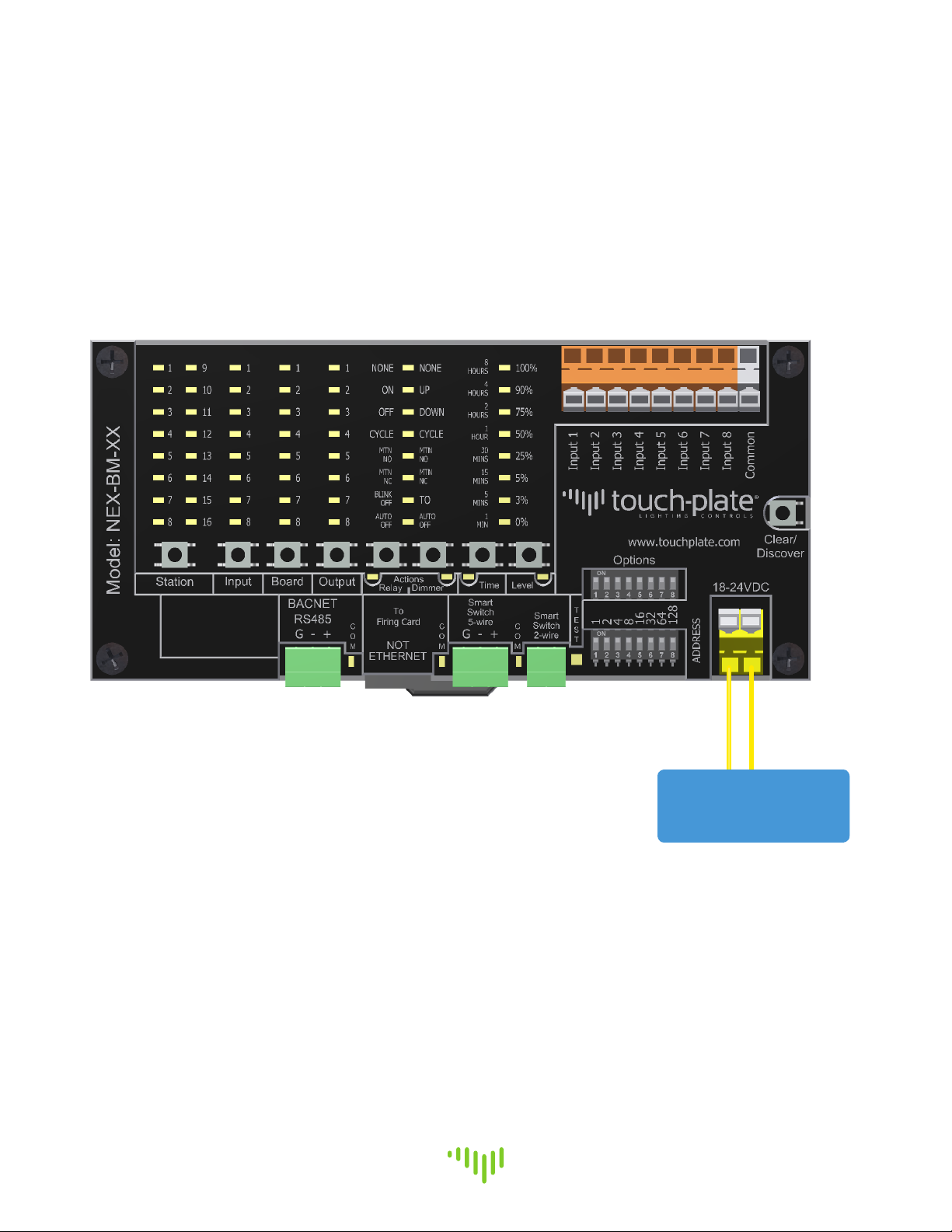
Nexus Power Wiring
To correctly bring power to the Nexus, use the wiring diagram below. Power must be a Class 2, Iso-
lated Transformer, with a rating of 18-24VDC. This will typically come from the factory pre-wired.
The power connection is not polarity sensitive.

Wired to 2-Wire
Station or Sensor
Page 6
www.touchplate.com
Touch-Plate® Lighting Controls
Nexus System Manual
Nexus 2-Wire Wiring
To correctly wire the 2-Wire connection to the Nexus, use the wiring diagram below.
•2-Wire Stations and Sensors are not polarity sensitive (topology free).
Wire must be Tappan 1680AB2/CMP (16 AWG, 2 Conductor, Twisted, Unshielded) or an equivalent wire.
Wired to 5-Wire
Station or Sensor
Touch-Plate® Lighting Controls
Nexus System Manual
Page 7
www.touchplate.com
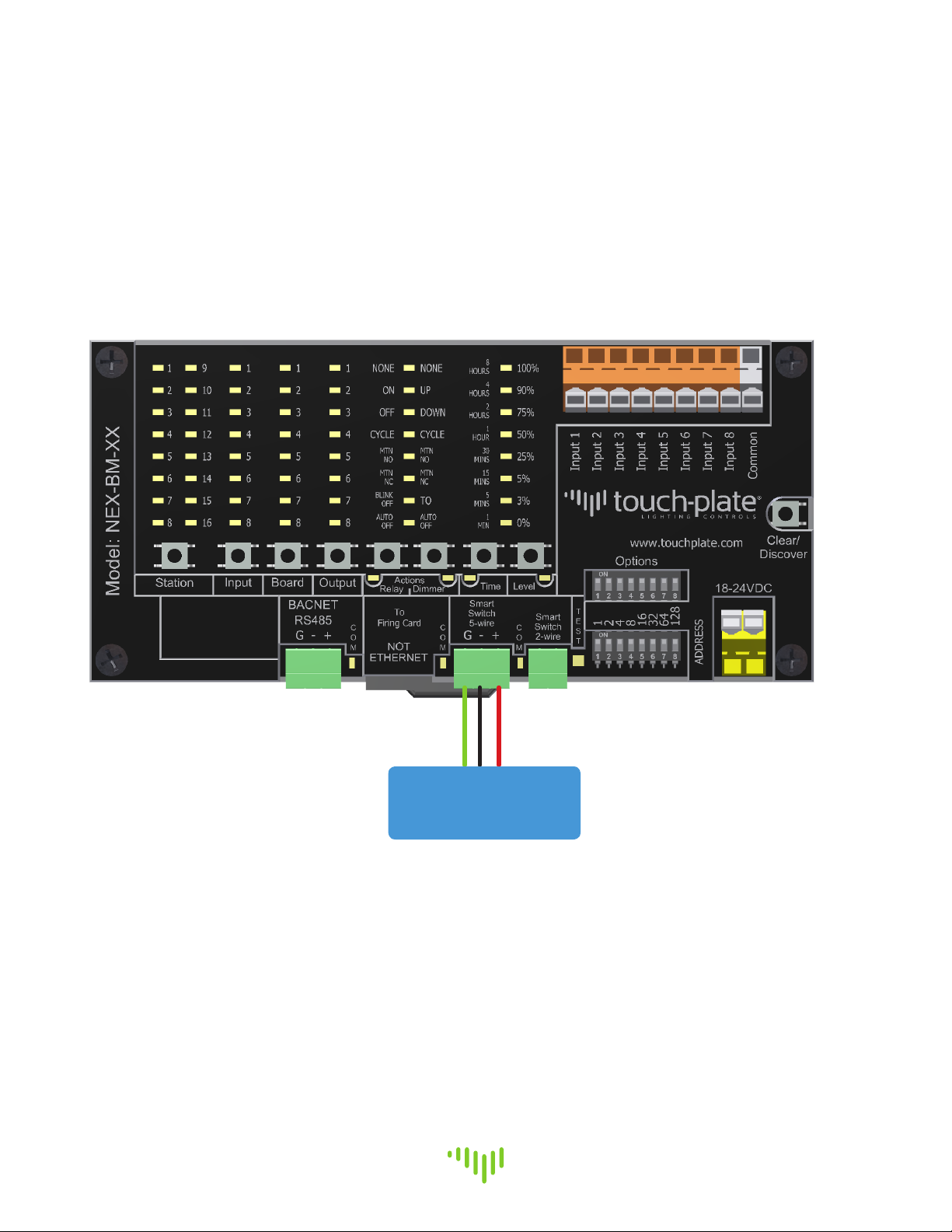
Nexus 5-Wire Wiring
To correctly wire the 5-Wire connection to the Nexus, use the wiring diagram below.
Wire must be Axlink 22/01PSH + 18/2C or an equivalent wire.

Wired to
Touch-Plate Firing
Card
Page 8
www.touchplate.com
Touch-Plate® Lighting Controls
Nexus System Manual
Nexus Firing Card Wiring
To correctly wire the Firing Card connection to the Nexus, use the wiring diagram below.
Wire must be Cat5e or an equivalent wire.
Typical items wired via the RJ-45 connection are: Touch-Plate Relay and Dimmer Firing Cards.

Green: (S)
Black: (-)
Red: (+)
Touch-Plate® Lighting Controls
Nexus System Manual
Page 9
www.touchplate.com
Nexus MS/TP RS485 Wiring
To correctly wire the RS485 connection to the Nexus, use the wiring diagram below.
•Shield or Ground for MS/TP RS485 connection must be isolated from the ground
on the power supply. Using the same ground will create a direct short across the
diode bridge and damage the unit.
Wire must be Liberty 18/2C SHLD or an equivalent wire.

Page 10
www.touchplate.com
Touch-Plate® Lighting Controls
Nexus System Manual
Nexus Softpatching
Softpatching is available for use with the Nexus, which will allow you to utilize the internal
software of the Nexus. This step will need to occur before any BACnet programming takes place.
For Standalone systems, this is the primary programming function.
Programming Contact Closure or Station Inputs
Use the programming diagram to setup your system. In this step contact closure buttons or station
buttons will be programmed. Each button and associated load will need to have its action pre-
determined before any programming takes place.
Each system will have different programming characteristics and this document does not show all
possible programming options. When Contact Closure Inputs are enabled they will always show up
as Station number 16.
Utilize Appendix IV and V for programming interface explanations.
1. Press the ‘STATION’ button multiple times until the LED is lit next to the Station Address that is
to be programmed.
2. Press the ‘BUTTON/INPUT’ button multiple times until the LED is lit next to the Button that is to
be programmed.
3. Press the ‘BOARD’ button multiple times until the LED is lit next to the Firing Card that is to be
programmed.
4. Press the ‘OUTPUT’ button multiple times until the LED is lit next to the Load that is to be
programmed.
5. Press the ‘RELAY ACTIONS’ or ‘DIMMER ACTIONS’ button multiple times until the LED is lit next
to the Action that is to be carried out by either the relay(s) or dimmer(s). If ‘AUTO OFF’ or ‘TO
ACTION’ is chosen, proceed to step 7. If not, proceed to step 6.
6. Press the ‘STATION’ or ‘BUTTON/INPUT’ button to move to the next Station Address or Button that
is to be programmed.
The next two steps are only to be used if the ‘Auto Off’ Action has been chosen or the ‘To Action’
has been chosen.
7. Press the ‘TIME’ button multiple times until the LED is lit next to the Time that the load is
to turn off at when using the Auto Off Action.
8. Press the ‘LEVEL’ button multiple times until the LED is lit next to the Level that the dimmer
is to dim to when using the To Action.
9. Press the ‘STATION’ button to move to the next Station Address that is to be programmed.

Touch-Plate® Lighting Controls
Nexus System Manual
Page 11
www.touchplate.com
Appendix I - Powering the Nexus
This step is used for replacing or installing a new Nexus only.
When the Nexus has power applied to it, it will go through a process to establish communication
and to identify all inputs and outputs. When the process is completed, communication to all input
and output devices can be verified.
Utilize the following steps to correctly startup the Nexus.
1. Verify Option Dip Switches 1 - 7 are in the OFF position, if the Inputs are being used.
If the Inputs are not being used, Option Dip Switches 1 - 8 need to be in the OFF position.
2. Bring power to the Nexus. The system will take a moment to boot up.
3. The LED “heartbeat” will begin flashing. This is the verification that power has been correctly
brought to the Nexus.
Appendix II - Discovery Mode
Discovery Mode is used to enable the Nexus to discover attached devices, report the addresses of
discovered devices, and save the configuration in the Nexus memory.
Discovery Mode is also used after enabling Contact Closure Switches, installation of any new
devices to the system, or after the initial powering up of the Nexus.
Use the following steps to correctly utilize Discovery Mode.
1. Turn ON Option DIP Switch #7.
2. Press the Discovery/Clear button for one second. The Nexus “heartbeat” will turn OFF.
The communication LED next to the Firing Card port will turn on. Allow several seconds to
complete the discovery of all connected input and output devices.
3. Discovered input addresses will light up the corresponding LED in the STATION section on the
programming interface. Verify that all inputs are discovered at the correct address.
4. Discovered output addresses will light up the corresponding LED in the BOARD section on the
programming interface. Verify that all outputs are discovered at the correct address.
5. To exit Discovery Mode, turn OFF Option DIP Switch #7. All the LEDs will turn OFF and the
Nexus “heartbeat” will flash. This will save the discovered configuration.
Appendix III - Clearing the Programming
Use the clearing the programming diagram to clear the programming on the Nexus. This clearing
will not clear out certain configuration parameters, such as the baud rate(s).
1. Press and hold the ‘STATION’ button. After a few seconds, the LEDs in the ‘STATION’, ‘INPUT’,
‘BOARD’, and ‘OUTPUT’ columns will light up.
2. As the ‘STATION’ button is held, the column LEDs will light in sequence, starting at the
bottom and move towards the top. After the top LEDs light up, all of the LEDs will clear
and this indicates that the programming is cleared.
3. Release the ‘STATION’ button.

Page 12
www.touchplate.com
Touch-Plate® Lighting Controls
Nexus System Manual
Appendix IV - Programming Interface Explanations
These explanations will help to understand each section of the Interface and its definition.
Section Number Definition
Station 1Address #1 on a control station, sensor, or bridge
2Address #2 on a control station, sensor, or bridge
3Address #3 on a control station, sensor, or bridge
4Address #4 on a control station, sensor, or bridge
5Address #5 on a control station, sensor, or bridge
6Address #6 on a control station, sensor, or bridge
7Address #7 on a control station, sensor, or bridge
8Address #8 on a control station, sensor, or bridge
9Address #9 on a control station, sensor, or bridge
10 Address #10 on a control station, sensor, or bridge
11 Address #11 on a control station, sensor, or bridge
12 Address #12 on a control station, sensor, or bridge
13 Address #13 on a control station, sensor, or bridge
14 Address #14 on a control station, sensor, or bridge
15 Address #15 on a control station, sensor, or bridge
16 Address #16 on a control station, sensor, or bridge
If Inputs are enabled, then it will correspond to the CCI Inputs
Input 1Control Station button #1, Sensor button #1, or Bridge Input #1
2Control Station button #2, Sensor button #2, or Bridge Input #2
3Control Station button #3, Sensor button #3, or Bridge Input #3
4Control Station button #4, Sensor button #4, or Bridge Input #4
5Control Station button #5, Sensor button #5, or Bridge Input #5
6Control Station button #6, Sensor button #6, or Bridge Input #6
7Control Station button #7, Sensor button #7, or Bridge Input #7
8Control Station button #8, Sensor button #8, or Bridge Input #8
Board 1Firing Card Address #1
2Firing Card Address #2
3Firing Card Address #3
4Firing Card Address #4
5Firing Card Address #5
6Firing Card Address #6
7Firing Card Address #7
8Firing Card Address #8
Output 1Relay or Dimmer #1
2Relay or Dimmer #2
3Relay or Dimmer #3
4Relay or Dimmer #4
5Relay or Dimmer #5
6Relay or Dimmer #6

Touch-Plate® Lighting Controls
Nexus System Manual
Page 13
www.touchplate.com
Appendix V - Programming Interface Explanations
Section Item Definition
Output (cont.) 7Relay or Dimmer #7
8Relay or Dimmer #8
Relay Actions None No action will occur
On The load turns ON with a button press
Off The load turns OFF with a button press
Cycle Each button press cycles the load between ON and OFF
MTN NO The load is OFF during the button press
MTN NC The load is ON during the button press
Blink OFF If the lights are on, a button press will turn them off and then quick-
ly turn them back on and the timer starts. If another button is
not pressed, after the set time, the lights will go off.
Auto OFF If the lights are off, they will turn on. After the set time they will
turn off. If the lights are on, they will stay on. After the set time,
the lights will turn off.
Dimmer Actions None No action will occur
Up The load dims up as the button is held
Down The load dims down as the button is held
Cycle Each button press cycles the load between ON and OFF
MTN NO The load is OFF during the button press
MTN NC The load is ON during the button press
To The button press dims the light to the preset level
Auto Off If the lights are off, they will turn on. After the set time they will
turn off. If the lights are on, they will stay on. After the set time,
the lights will turn off.
Time 8 Hours Used with Auto Off option; light will turn off after 8 hours
4 Hours Used with Auto Off option; light will turn off after 4 hours
2 Hours Used with Auto Off option; light will turn off after 2 hours
1 Hour Used with Auto Off option; light will turn off after 1 hour
30 Mins Used with Auto Off option; light will turn off after 30 minutes
15 Mins Used with Auto Off option; light will turn off after 15 minutes
5 Mins Used with Auto Off option; light will turn off after 5 minutes
1 Min Used with Auto Off option; light will turn off after 1 minute
Level 100% The load will dim to 100% out of 100%
90% The load will dim to 90% out of 100%
75% The load will dim to 75% out of 100%
50% The load will dim to 50% out of 100%
25% The load will dim to 25% out of 100%
5% The load will dim to 5% out of 100%
3% The load will dim to 3% out of 100%
0% The load will dim to 0% out of 100%

Page 14
www.touchplate.com
Touch-Plate® Lighting Controls
Nexus System Manual
Appendix VI - Option Dip Switches
The Option DIP Switches are used to set different functions. Use the following guide as to what
each of the Option DIP Switches are used for.
Function BACnet/
Standalone #12345678
No Function N/A 1-- -- -- -- -- -- -- --
No Function N/A 2-- -- -- -- -- -- -- --
Enables setting the
MS/TP Baud Rates for
communication with the
BACnet MS/TP network
and for communication
with the Firing Card(s).
BACnet 3OFF OFF ON OFF OFF OFF OFF OFF
Enables the auto
creation of BI objects
1 - 128.
BACnet 4OFF OFF OFF ON OFF OFF OFF OFF
Reads all the parameters
from attached sensors
and updates the sensor
objects. If a remote is
used to configure the
sensor, the changes are
not sent back to the
Nexus automatically.
BACnet &
Standalone
5OFF OFF OFF OFF ON OFF OFF OFF
Runs the diagnostic All
On/Off test.
CCI1=All On;CCI2=All Off
BACnet &
Standalone
6OFF OFF OFF OFF OFF ON OFF OFF
Runs the Discover mode. BACnet &
Standalone
7OFF OFF OFF OFF OFF OFF ON OFF
Performs normal clear/
factory reset operation.
BACnet &
Standalone
7OFF OFF OFF OFF OFF OFF OFF OFF
Contact Closure Switch
Inputs are enabled and
mapped to Station 16.
BACnet &
Standalone
8OFF OFF OFF OFF OFF OFF OFF ON
Contact Closure Switch
Inputs are disabled
and Address #16 is
recognized.
BACnet &
Standalone
8OFF OFF OFF OFF OFF OFF OFF OFF

Touch-Plate® Lighting Controls
Nexus System Manual
Page 15
www.touchplate.com
Troubleshooting Guide
If no response occurs when the system is powered up, use the following steps to identify the
problem.
1. Look for the LED indicator to be blinking on the Nexus.
a. For the indicator to be blinking, power has to be correctly brought to the system.
b. If the LED indicator is not blinking, confirm power connections and then contact
the factory for assistance.
If the communications LED does not stop flashing, the LEDs on the control stations, and/or output
boards do not flash.
1. Verify that the wiring is correct.
2. Verify that all devices are connected to power.
3. Verify the baud rate on the Nexus.

Page 16
www.touchplate.com
Touch-Plate® Lighting Controls
Nexus System Manual
Frequently Asked Questions
1. What if there is no response from the main controller?
a. Verify that the MS/TP cable is correctly connected.
b. Verify that there are not conflicts with the MS/TP MAC addresses. Each device on a
MS/TP network must have unique MS/TP MAC address.
c. Run the Device Discovery. Upon running this, verify that any communication is
possible with the Nexus. If this is not the problem then contact Touch-Plate.
2. Why are the relays not able to be cycled from the front end controller?
a. Verify that another controller does not have the relay locked out by using a higher
priority.
b. Verify that the relay output boards are properly communicating with the Nexus.
3. Are the Contact Closure Inputs dry contacts?
a. Yes they are dry contacts. Common outputs are what put out voltage. The common
output on the Nexus puts out +24V.

Touch-Plate Nexus System Manual
Revision: 2.0a
Table of contents
Popular Controllers manuals by other brands

Cleco
Cleco DGD mPro400GC installation manual

Edwards
Edwards PC2K manual

Grozone Control
Grozone Control The Simple One CLIMATE CONTROLLER Advanced user's guide

Mitsubishi
Mitsubishi MELSEC Q Series user manual

Clare Controls
Clare Controls CLIQ.host Installation sheet

HighPoint
HighPoint R1000 Series Quick installation guide


