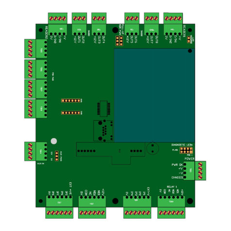
TouchStar Evolution Product manual

1
EVOLUTION DOOR CONTROLLER
(RS-485 VERSION)
INSTALLATION AND MAINTENANCE GUIDE
MAN069-01
OCTOBER 2018

2
GENERAL INFORMATION
IMPORTANT SAFETY INFORMATION
This door con roller has been designed o mee in erna ional safe y s andards bu , like
any elec rical equipmen , care mus be aken if safe y is o be assured. Read hese safe y
ins ruc ions before ins alla ion and opera ion of he door con roller. Re ain his ins alla ion
guide for fu ure use.
DO
DODO
DO ensure ha all he elec rical connec ions (including power connec ions
and in erconnec ions be ween pieces of equipmen ) are properly made in
accordance wi h he manufac urers ins ruc ions. The equipmen mus be
The equipmen mus be The equipmen mus be
The equipmen mus be
ear hed
ear hedear hed
ear hed.
DO
DODO
DO consul your dealer if you are in any doub abou ins alla ion, opera ion
or safe y of he equipmen .
DO
DO DO
DO ensure ha all Heal h and Safe y regula ions are me regarding every
aspec of your Access Con rol sys em.
DO
DODO
DO remember ha some equipmen con inues o opera e af er mains
power has been removed, because of an in ernal ba ery. In such cases a
qualified Service Engineer mus disconnec he ba ery before a emp ing
o service he equipmen .
DO NOT
DO NOTDO NOT
DO NOT con inue o opera e he equipmen if you are in any doub abou i
working normally .
DO NOT
DO NOTDO NOT
DO NOT remove any cover fas enings unless you are qualified o do so.
Even hen isola e from he power connec ion before you s ar .
DO NOT
DO NOTDO NOT
DO NOT allow he equipmen o be exposed o rain or mois ure o her han
permi ed by he equipmen 's specifica ion.
DO NOT
DO NOTDO NOT
DO NOT a emp o service any ba ery fi ed o he equipmen . If he
ba ery fi ed o he circui board is faul y, re urn he comple e circui board
o an approved Service Cen re. Removable ba eries may be replaced by a
qualified Service Engineer.
WARNING To comply wi h in erna ional safe y s andards he a.c. supply mus be rou ed
via an easily accessible isola ing device. This device mus have a con ac gap of a leas
3mm ( hree millime res) and should break bo h Live and Neu ral conduc ors
simul aneously. If he Neu ral conduc or can be reliably iden ified he device may be in he
Live conduc or only.
POWER REQUIREMENT...
......
... The Door Con roller requires a mains supply ra ed a 220 -
240V a.c./50VA 49Hz o 61Hz.

3
CONTENTS
GENERAL INFORMATION
IMPORTANT SAFETY INFORMATION 2
POWER REQUIREMENT 2
INTRODUCTION
INTRODUCTION 4
SITING THE DOOR CONTROLLER
LOCATING THE DOOR CONTROLLER 5
CABLING 5
DIMENSIONS 5
DOOR CONTROLLER PCB CONNECTIONS
PCB WIRING AND LINKS DIAGRAM PCB249ASX 6
CONNECTING A READER
READERS 7
PIN PAD 7
CONNECTING A LOCK
FAIL OPEN LOCK 8
RELAY CONTACTS 8
FAIL CLOSED LOCK 9
CONNECTING SWITCHES I/O TO THE DOOR CONTROLLER
OUTPUTS 10
DIGITAL INPUTS 10
COMMISSIONING THE DOOR CONTROLLER
CONNECTING POWER 11
CURRENT CONSUMPTION 11
SWITCH SETTINGS 12
INDICATORS 13
OPERATION 13
CONNECTING THE COMMUNICATION CABLE 13
CARE AND MAINTENANCE
BOARD REMOVAL 14
MEDIA PREPARATION 14
READER CLEANING 14

4
INTRODUCTION
This guide provides he informa ion necessary o ins all a door con roller. I includes
moun ing and cabling requiremen s and ins ruc ions o enable he device o be
commissioned.
This door con roller (as opposed o he s andard Evolu ion door con roller)
communica es over RS
RSRS
RS-
--
-485
485 485
485 They are connec ed via 2 wire communica ion cable o he
ELSA
ELSA ELSA
ELSA (Evolu ion Line Sharing Adap er) This in urn is connec ed via LAN o he server
running he Evolu ion sof ware.
NOTE: These de ails along wi h all o her relevan informa ion can also be found in he documen
MAN047
MAN047MAN047
MAN047-
--
-XX
XXXX
XX.

5
SITING THE DOOR CONTROLLER
LOCATING THE DOOR CONTROLLER... The door con roller should be loca ed in a
posi ion away from ex remes of hea , dus vibra ion and fumes. I should be pro ec ed
from excessive condensa ion, hosing and direc sunligh . Choose a loca ion as near as
possible o bo h Reader and he device o be opera ed, ha will allow room for
main enance. The door con roller is fixed o he moun ing surface by using up o four
moun ing holes in he rear of he case. Use plas ic plugs if screwing o a solid wall.
CABLING... Cabling can en er he door con roller from he op or bo om via he case
knockou s for cable glands or 20mm condui en ry. Communica ions is via RS
RSRS
RS-
--
-485
485 485
485
connec ion o he ELSA using s andard elephone cable ype CW 1308 or s andard
ne work cable, such as CAT5.
Manufac urer specified cable should be
used o connec be ween he door
con roller and he readers, PIN pad,
door lock, urns ile or barrier o be
opera ed. If an alarm, break glass,
remo e en ry swi ch, or door open
swi ch is required, considera ion of
hese cable requiremen s should also
be made.
DIMENSIONS...The door con roller is
housed in a me al box ha is 36cm x
36cm x 9cm.

6
DOOR CONTROLLER PCB CONNECTIONS
Reader Power
Lock
RTE Bu on
PCB249ASX with PCB251ASX fitted
Sounder
Reader

7
CONNECTING A READER
READERS... The main ype of reader ha he door con roller is designed o use is
proximi y. However, i will also work wi h s andard clock/da a in erface, magne ic s ripe
and barcode readers. Our mos common readers are lis ed below oge her wi h
connec ion de ails.
NOTES: If wiegand inpu is required hen LK9
LK9LK9
LK9 is made and he
wiegand bi value is se in sof ware. Sui able cable mus always be
used when connec ing readers o he door con roller. Ou pu s will
be user configurable in he sof ware o give S a us informa ion a
reader LED’s. +V
+V +V
+V connec ion on bo h reader connec ors can be
linked o +5V
+5V +5V
+5V or +12V
+12V +12V
+12V dependan on link posi ion, as shown in he
diagram. Only change his link if you are sure abou he
requiremen s of he reader. Fac ory se a +5V
+5V+5V
+5V.
READER CONNECTION DETAILS… Please no e ha wire colours may vary dependan on
reader manufac urer and/or cable used.
PIN PAD... These are connec ed where shown and in accordance wi h he pin pad manual.
READER TYPE
READER TYPEREADER TYPE
READER TYPE
EVO PCB
EVO PCBEVO PCB
EVO PCB
PP1
PP1PP1
PP1-
--
-MPROX
MPROXMPROX
MPROX
HID HPRXP
HID HPRXPHID HPRXP
HID HPRXP
PP1
PP1PP1
PP1-
--
-481
481481
481
+V RED RED RED
C/IN1 WHITE WHITE WHITE
D/IN2 GREEN GREEN GREEN
0v BLACK BLACK BLACK
OUT? ORANGE ORANGE ORANGE
OUT? BROWN BROWN BROWN
+12v RED RED
CHASS SCREEN SCREEN
PC898
PC898PC898
PC898-
--
-001
001001
001
RED
YELLOW
BLUE
GREEN
PP1
PP1PP1
PP1-
--
-RX4
RX4RX4
RX4
RED
WHITE
GREEN
BLACK
ORANGE
BROWN
PP1-RX4

8
CONNECTING A LOCK
The relay con ac s have in buil pro ec ion agains ransien spikes bu when using a pure
induc ive load wi h no back EMF pro ec ion, ex ra pro ec ion mus be fi ed. This can be
in he form of a me al-oxide varis or (MOV) or diodes (supplied). The posi ive (+) supply
of an induc ive load should be connec ed o he ca hode of he diode and he nega ive (-)
o he anode.
FAIL OPEN LOCK... The fail open lock will leave a door unlocked when he power supply
cu s ou . This means ha power is con inuously applied o he door o preven he
mechanism from opening. When a valid card is swiped, he door con roller cu s power o
he lock and he door can be opened. If power fails unexpec edly, he lock is also released,
o leave he door unsecured. This ype of lock is sui able for he in ernal doors of a
building.
The drawing above depic s a fail open lock wi h a moni ored break glass riggering inpu
4 when he break glass is pressed o open door. If a break glass uni is no required LK6
can be lef connec ed. If a break glass is no used, a mechanical me hod of releasing he
door mus be supplied.
IMPORTANT NOTE: LK6
LK6LK6
LK6 links 0V
0V0V
0V o he COM
COMCOM
COM connec ion of he relay ou pu . This mus be
fi ed in his configura ion. If connec ed o a Barrier/Turns ile, his link mus be removed
for Vol s free opera ion.
RELAY CONTACTS: The relay con ac s are pro ec ed agains ransien spikes by non-
polarised suppression. Relay con ac ra ing: 1A @ 30V for each pole.
Breakglass
NC
Breakglass
NO
Breakglass
COM
Lock
Lock

9
CONNECTING A LOCK
FAIL CLOSED LOCK... The fail closed lock requires power o be applied o open i . If
power fails, he door will be fail locked. The door con roller applies power o he lock
when a valid card is swiped. The lock is released and he door can be opened. This ype of
lock is sui able for he ex ernal doors of a building, al hough i should be no ed ha in a
handle or break glass should always be provided for emergency egress.
The drawing above depic s a fail closed lock wi h moni oring and push bu on o exi .
NOTE: LK6
LK6LK6
LK6 is fi ed and links 0V
0V 0V
0V o he COM
COM COM
COM connec ion of he relay ou pu .
If wo locks are con rolled from he same relay i is recommended ha one lock is wired
o each pole. Lock 1 o N/O1
N/O1 N/O1
N/O1 Lock 2 N/O2
N/O2N/O2
N/O2.
Lock COM
Lock NO
Lock +V
Lock 0V
RTE 0V
RTE +V

10
CONNECTING SWITCHES & I/O
OUTPUTS... These are open collec or ransis ors which can drive a load connec ed o he
in ernal 12V
12V12V
12V supply or an ex ernal supply of up o 12V
12V12V
12V. When he ou pu is ON
ON ON
ON i can sink a
curren of 100mA
100mA100mA
100mA.
This example shows a siren connec ed o he in ernal 12V
12V12V
12V supply.
To use a mains powered siren, connec he alarm ou pu o a sui able ex ernal relay. These
however, are in egral on some makes of siren.
DIGITAL INPUTS... These are op o-coupled inpu s ha can be linked o use ei her he
power INT
INT INT
INT supply, or an ex ernal supply of up o 20V
20V20V
20V. If an ex ernal supply is used LK5
LK5 LK5
LK5
mus be moved o o her posi ion and he ex ernal +V
+V +V
+V connec ed o he EXT+VE
EXT+VE EXT+VE
EXT+VE
connec ion. The ex ernal swi ch or device mus be capable of sinking 5mA
5mA5mA
5mA o opera e he
inpu .
NOTE: All inpu s can be se in he sof ware o be ac ive High or Low.
This example shows a door swi ch connec ed o he in ernal power supply. LK5
LK5 LK5
LK5 mus be
fi ed as shown for his configura ion. If ex ernal power supply is o be used LK5
LK5 LK5
LK5 mus be
moved o o her loca ion as shown in diagram above and ex ernal +V
+V +V
+V connec ed o
EXT+VE
EXT+VE EXT+VE
EXT+VE and 0V
0V0V
0V o 0V
0V0V
0V.
+V
0V

11
COMMISSIONING THE DOOR CONTROLLER
CONNECTING POWER... The Door Con roller should be connec ed using 3A 240V PVC
shea hed cable, from he in ernal fused erminal block, o an easily accessible isola ing
device as follows:-
• Connec he LIVE (BROWN)
LIVE (BROWN) LIVE (BROWN)
LIVE (BROWN) wire o he erminal marked L
LL
L (LIVE) in
he isola or.
• Connec he NEUTRAL (BLUE)
NEUTRAL (BLUE) NEUTRAL (BLUE)
NEUTRAL (BLUE) wire o he erminal marked N
N N
N
(NEUTRAL) in he isola or.
• Connec he EARTH (GREEN & YELLOW)
EARTH (GREEN & YELLOW) EARTH (GREEN & YELLOW)
EARTH (GREEN & YELLOW) wire o he ear h erminal
marked in he isola or.
The in ernal erminal block is fi ed wi h a 3.15AT ime delay fuse. I is also
impor an ha he clamp is used o secure he incoming cable as shown, wi h
he ie wrap securing he wires, ensuring ha hey are clear of he chassis.
CURRENT CONSUMPTION... The following informa ion should be used as a rough guide
only:-
PC898-001
-
--
-
Bar Code Reader 50mA max
PP1-481-MIF - Mifare Reader 100mA max
PP1-RX4 - Universal Reader 250mA max
PP8-HPRXP - Reader 75mA max
PP8-MPROX - Reader 75mA max
PP1-741-SC - Magne ic S ripe Reader 20mA
PC190-116 - Magne ic S ripe Reader 10mA
PC-PTPD-0XX - PIN Pad 4mA
La ch Lock - 250mA
Magne ic Lock - 500mA
Digi al Inpu - 5mA
NOTES:
• The curren ra ings shown for door locks are approxima e values only. Ac ual curren
ra ings should be available from he manufac urer.
• If using Magne ic locks i is par icularly impor an o ensure ha he Door Con roller
can supply hem as hey have a high curren consump ion compared wi h mos o her
ex ernal devices.
• I is impor an o remember ha he more ex ernal devices ha are connec ed, he
less he amoun of ime i will opera e if he mains power is removed.

12
COMMISSIONING THE DOOR CONTROLLER
SWITCH SETTINGS... The RS
RSRS
RS-
--
-485
485 485
485 in erface is provided by a PCB251ASX
PCB251ASX PCB251ASX
PCB251ASX assembly. This
board has a bank of six swi ches. These are used o specify he communica ion speed and
uni iden i y. There is also a jumper J5
J5J5
J5 o enable an RS
RSRS
RS-
--
-485
485 485
485 ermina ion resis or.
Swi ch alloca ion is as follows:
SW1 SW2 SW3 SW4 SW5 SW6 RESULT
OFF 9600 Baud
ON 19200 Baud
OFF OFF OFF OFF OFF ID=0
OFF OFF OFF OFF ON ID=1
OFF OFF OFF ON OFF ID=2
OFF OFF OFF ON ON ID=3
OFF OFF ON OFF OFF ID=4
OFF OFF ON OFF ON ID=5
OFF OFF ON ON OFF ID=6
OFF OFF ON ON ON ID=7
OFF ON OFF OFF OFF ID=8
OFF ON OFF OFF ON ID=9
OFF ON OFF ON OFF ID=10
SW2 to SW6 connue in a bina y count up to ID=30

13
COMMISSIONING THE DOOR CONTROLLER
INDICATORS... The PCB251ASX
PCB251ASX PCB251ASX
PCB251ASX assembly has a single indica or ha aims o show he
s a us of opera ion. This is achieved by producing several blips followed by a period of
off. The number of blips represen s:
2
22
2 – Idle
3
33
3 – Being polled
4
44
4 – (Reserved)
5
55
5 – Tes mode
OPERATION… Opera ionally, he device should ac much like a s andard EVO door
con roller; bu , because of he rela ive slow communica ion speeds, on-line opera ion will
be no iceably slower and should be avoided.
CONNECTING THE COMMUNICATION CABLE … Each ne work cable connec ed o a Door
Con roller requires one wis ed pair cable wi h an overall ne work leng h of 5000 me res
maximum. S andard elephone cable ype CW 1308
CW 1308 CW 1308
CW 1308 is ideal, bu any equivalen wis ed
pair cable can be used. The polari y of he signal is impor an . Ensure ha he +ve
+ve +ve
+ve
connec ion is linked o +ve
+ve +ve
+ve and –
––
–ve
ve ve
ve o –
––
–ve
veve
ve.
Connec ions are as shown below:
Connec or s rip on
ELSA PCB252ASX
PCB252ASXPCB252ASX
PCB252ASX

14
CARE AND MAINTENANCE
BOARD REMOVAL... Each individual door con roller is fi ed wi h one main circui board
(PCB249ASX
PCB249ASXPCB249ASX
PCB249ASX), a processor board (PCB234ASX
PCB234ASXPCB234ASX
PCB234ASX) and RS
RSRS
RS-
--
-485
485 485
485 board (PCB251ASX
PCB251ASXPCB251ASX
PCB251ASX)
a ached o i . These can be removed and replaced bu his mus no be done by anyone
no rained o do so. If i is necessary o remove he board, please proceed as follows:-
Remove power from he door con roller.
Remove he screws securing he op cover o he uni .
Unplug he cables from connec ors on he circui board (no e orien a ion).
Disconnec all screw connec ors by unplugging hem from heir respec ive socke s
(no e orien a ion and loca ion).
Remove he screw securing he PCB251ASX
PCB251ASXPCB251ASX
PCB251ASX RS-485 board and/or.
Remove he 4 screws securing he PCB234ASX
PCB234ASXPCB234ASX
PCB234ASX processor board and/or.
Remove he 6 screws securing he PCB249ASX
PCB249ASXPCB249ASX
PCB249ASX circui board o he chassis.
Lif he circui board ou of he case.
Before ins alling replacemen board, ensure ha all links are fi ed in exac ly he same
posi ions as on he original board.
Replace he boards in he reverse order, aking care o connec all pins be ween he
sa elli e board and he main board correc ly.
MEDIA PREPARATION... To ensure he bes performance from he door con roller and
associa ed readers i is essen ial o use only good quali y magne ic s ripe, proximi y or
barcode media. Con ac your dealer or TouchS ar cus omer service depar men for
informa ion abou he prepara ion of badges or o her media. In par icular, check ha
cards and badges are fla , smoo h and in good condi ion, ha he ink used for bar code
prin ing is op ically black a infra red frequencies and ha he codes are compa ible wi h
he sof ware package.
READER CLEANING... In unusually dir y si ua ions i may be necessary o arrange for he
Bar code or Magne ic s ripe readers o be cleaned regularly. This can be done easily, using
readily available cleaning cards. Proximi y readers in a challenging environmen should be
wiped gen ly wi h a clo h o ensure hey are clean.

15
HEAD OFFICE
TouchStar ATC Limited
Access | Time | CCTV
Maple Barn,
Beeches Farm Road,
Uckfield,
Eas Sussex TN22 5QD
REPAIRS
TouchStar ATC Limited
Access | Time | CCTV
Uni 49,Vinehall Business Cen re,
Vinehall Road,
Rober sbridge,
Eas Sussex TN32 5JW
T: 0845 3379 155
W: www.touchstar-atc.com
Table of contents
Other TouchStar Controllers manuals
Popular Controllers manuals by other brands
Veldhuis Digital Engineering
Veldhuis Digital Engineering NV4C2H Operator's manual
Valcom
Valcom PagePac V-5335100 quick start guide

EMKO
EMKO EPC-1 instruction manual
ALLEN & HEATH
ALLEN & HEATH iDR-4 Service information
Weathermatic
Weathermatic SmartLink SmartLine owner's manual
BARTH Elektronik
BARTH Elektronik STG-65 manual
