TOUGH-WORKS SSA16V User manual

16 IN. SCROLL SAW
WITH PINLESS BLADE HOLDER
INSTRUCTION
MANUAL
IMPORTANT:
For your own safety, read and follow all of the Safety
Guidelines and Operating Instructions before operating
this product.
SSA16V

2
TABLE OF CONTENTS
SPECIFICATIONS
TABLE OF CONTENTS
BD4603
TABLE OF CONTENTS ...............................................................................................
2
SAFETY GUIDELINES ................................................................................................
5
7
PACKAGE CONTENTS ..............................................................................................
8
KEY PARTS DIAGRAN
..................................................................................................
9
ASSEMBLY/MOUNTING
........................................................................................
12
OPERATION .................................................................................................................
16
MAINTENANCE ............................................................................................................
17
TROUBLESHOOTING GUIDE .....................................................................................
18
EXPLONED VIEW .........................................................................................................
19
PARTS LIST ..................................................................................................................
22
WARRANTY ..................................................................................................................
23
ELECTRICAL SAFETY .................................................................................................
SSA16V
Input 120 VAC ,AC Only, 60Hz / 1.2 A
No Load Speed 550-1,650 r/min(RPM)
Throat
Blade Length
SPECIFICATIONS .......................................................................................................
2
16 in.
5 in.pin or plain
BD4603
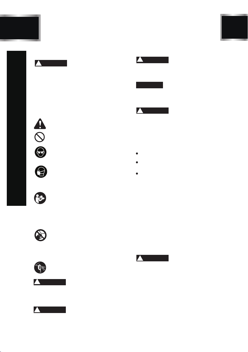
SAFETY GUIDELINES
3SSA16V
SAFETY ALERT:
Precautions that involve your safety.
Indicates an imminently hazardous situation
which, if not avoided, will result in death or se-
Indicates a potentially hazardous situation
which, if not avoided, could result in death or
Indicates a potentially hazardous situation
which, if not avoided,may result in minor or
moderate injury.
Used without the safety alert symbol indic-
ates potentially hazardous situation which, if
not avoided, may result in property damage.
WARNING
DANGER!
CAUTION
!
NOTICE
PROHIBITION
WEAR EYE PROTECTION:
Always wear safety goggles or safety
glasses with side shields.
WEAR RESPIRATORY AND HEARING
PROTECTION:
Always wear respiratory
and hearing
READ AND UNDERSTAND INSTRU-
CTION MANUAL:
To reduce the risk of injury, user and all
bystanders must read and understand
instruction manual before using this
product.
KEEP HANDS AWAY FROM THE MO-
VING PART AND CUTTING SURFACE:
Failure to keep your hands away from
the moving part and cutting surface
will result in serious personal injury.
SUPPORT AND CLAMP WORK
SAFETY GUIDELINES
Your power tool and its Instruction Manual
may contain “WARNING ICONS”(a picture)
symbol intended to alert you to and/or instruct
you how to avoid a potentially hazardous co-
ndition). Understanding and heeding these
symbols will help you operate your tool better
and safer. Shown below are some of the sy-
mbols you may see.
WARNING
!!
protection.
rious injury.
serious injury.
Some dust created by power sanding, sawing,
grinding,drilling and other construction ac-
tivities contains chemicals known to the
state of California to cause cancer, birth
defects or other reproductive harm. Some
examples of these chemicals are:
Lead from lead-based paints.
Crystalline silica from bricks and cement
and other masonry products.
Arsenic and chromium from chemically-
treated lumber.
WARNING
!
Your risk from these exposures varies, depe-
nding on how often you do this type of work.
To reduce your exposure to these chemicals:
work in a well ventilated area and work with
approved safety equipment such as dust masks
that are specially designed to filter out mi-
croscopic particles. Avoid prolonged contact
with dust from power sanding, sawing, gri-
nding, drilling, and other construction activi-
ties. Wear protective clothing and wash exposed
areas with soap and water. Allowing dust to
get into your mouth, eyes, or lay on the skin
may promote absorption of harmful chemicals.
WARNING
!
To avoid electrical hazards, fire hazards or damage
to the tool, use proper circuit protection.This tool
is wired at the factory for 110-120 Volt operation.
It must be connected to a 110-120 Volt /15 Ampere
time delay fuse or circuit breaker. To avoid shock
or fire, replace power cord immediately if it is worn,
cut or damaged in any way.
Before using your tool, it is critical that you read
and understand these safety rules. Failure to follow
these rules could result in serious injury to you
or damage to the tool.

4
SSA16V
GENERAL SAFETY INSTRUCTIONS
BEFORE USING THIS POWER TOOL
Safety is a combination of common sense,
staying alert and knowing how to use your
power tool.
To avoid mistakes that could cause serious
injury, do not plug the tool in until you have
read and understood the following.
Read all instructions before operating
product.Failure to follow all instructions listed
below may result in electric shock, fire and
/or serious injury.
1. READ and become familiar with the
entire Instruction Manual. LEARN
the tool’s application, limitations and
and possible hazards.
2. KEEP GUARDS IN PLACEand in working
order.
3. KEEPWORK AREACLEAN. Cluttered
areas and benches invite accidents.
4. DO NOT USE IN DANGEROUS
ENVIRONMENTS. Do not use power tools
in damp locations, or expose them to rain
or snow. Keep work area well lit.
5. KEEP CHILDREN AWAY. All visitors and
bystanders should be kept a safe distance
from work area.
6. DO NOT FORCE THE TOOL. It will do the
job better and safer at the rate for which it
was designed.
7. WEAR PROPER APPAREL.Do not wear
loose clothing, gloves, neckties, rings,
bracelets or other jewelry which may get
caught in moving parts. Nonslip footwear
is recommended. Wear protective hair
covering to contain long hair.
8. ALWAYS WEAR EYE
PROTECTION. Any power tool can
throw foreign objects into the eyes
ALWAYS wear Safety Goggles (not
glasses) that comply with ANSI Safety
standard Z87.1. Everyday eyeglasses
have only impact–resistant lenses. They
ARE NOT safety glasses. NOTE:Glasses
or goggles not in compliance with ANSI
Z87.1 could seriously injure you when
they break.
9. WEAR A FACE MASK OR
DUST MASK.Sanding operation
produces dust.
10. DISCONNECT TOOLS FROM POWER
SOURCE before servicing, and when
changing accessories such as blades,
bits and cutters.
WARNING
!
12. USE RECOMMENDED ACCESSORIES.
Consult this Instruction Manual for
recommended accessories. The use of
improper accessories may cause risk of
injury to yourself or others.
13. NEVER STAND ON THE TOOL. Serious
injury could occur if the tool is tipped
or if the cutting tool is unintentionally
contacted.
14. MAINTAIN TOOLS WITH CARE. Keep
tools sharp and clean for best and safest
performance. Follow instructions for
lubricating and changing accessories.
and could cause permanent eye damage.
11.USE PROPER EXTENSION CORDS.
Make sure your extension cord is in
good condition.When using an extension
cord, be sure to use one heavy enough
to carry the current your product will draw.
An undersized cord will result in a drop
in line voltage and in loss of power
which will cause the tool to overheat.
The table on page 8 shows the correct
size to use depending on cord length
and nameplate ampere rating. If in
doubt, use the next heavier gauge.
The smaller the gauge number, the
heavier the cord.
15.CHECK FOR DAMAGED PARTS.
Before further use of the tool, a guard or
other part that is damaged should be
SAFETY GUIDELINES

5SSA16V
18.
Dust generated from certain materials
can be hazardous to your health. Always
operate saw in well-ventilated area and
provide for proper dust removal.
19.
People with electronic devices, such as
pacemakers, should consult their ph-
ysician(s) before using this product.
close proximity to a heart pacemakercould
cause interference or failure of the pacemaker.
20. WEAR HEARING PROTECTION
to reduce the risk of induced hearing
loss.
WARNING
!
DANGER
!
carefully checked to determine that it
will operate properly and perform its
intended function– check for alignment
of moving parts, binding of moving parts,
breakageof parts, mounting and any other
conditions that may affect its operation.
A guard or other part that is damaged
should be properly repaired or replaced.
16. NEVER LEAVE THE TOOL RUNNING
UNATTENDED. TURN THE POWER “OFF”.
Do not walk away from a running tool until
the blade comes to a complete stop and the
tool is unplugged from the power source.
17. DO NOT OVERREACH. Keep proper footing
and balance at all times.
SPECIFIC SAFETY RULES
1. FIRMLYCLAMP OR BOLT the tool to a
workbench or table at approximately hip
height.
2. KEEP HANDS AWAY FROM CUTTING AREA.
Do not reach underneath work or in blade
cutting path with hands and fingers for any
reason. Always turn the power off.
3. BE SURE THE BLADE CLEARS THE
WORKPIECE.
Never start the saw with the blade touching the
workpiece.Allow motor to come up to full speed
before starting cut.
4. MAKE SURE THE WORK AREA HAS
AMPLE LIGHTING
to see the work and that no obstructions will int-
erfere with safe operation BEFORE performing
any work using the saw.
5. ALWAYS TURN OFF THE SAW
before disconnecting it to avoid accidental starting
when reconnecting to power supply. NEVER
leave the saw unattended while connected to a
power source.
6. TURN OFF TOOL and wait for saw blade to
come to a complete stop before moving work-
piece or changing settings.
7. IF THE POWER SUPPLY CORD IS DAMAGED,
it must be replaced only by the manufacturer or
by an authorized service center to avoid risk.
8. ALWAYS SUPPORT LARGE WORKPIECES
while cutting to minimize risk of blade pinching
and kickback. Saw may slip, walk or slide while
cutting large or heavy boards.
9. SAVE THESE INSTRUCTIONS.
Refer to them frequently and use them to instruct
other users. If you loan someone this tool, loan
them these instructions also.
SAFETY GUIDELINES

6
SSA16V
ELECTRICAL SAFETY
C
EXTENSION CORDS
Use only 3-wire extension cords that have 3-prong
grounding plugs and 3-pole receptacles that accept
the tool's plug. When using a power tool at a co-
nsiderable distance from the power source, use an
extension cord heavy enough to carry the current
that the tool will draw.An undersized extension cord
will cause a drop in line voltage, resulting in a loss
of power and causing the motor to overheat. Use
the chart provided below to determine the minimum
wire size required in an extension cord. Only round
jacketed cords listed by Underwriter's Laboratories
(UL) should be used.
When working with the tool outdoors, use an ext-
ension cord that is designed for outside use. This
is indicated by the letters “W-A” or “W” on the cord’s
jacket.
Before using an extension cord, inspect it for loose
or exposed wires and cut or worn insulation.
Keep the extension cord clear of the working area.
Position the cord so that it will not get caught on
lumber, tools or other obstructions while you are
working with a power tool. Failure to do so can result
in serious personal injury.
WARNING
!
Check extension cords before each use. If da-
maged replace immediately. Never use product
with a damaged cord since touching the damaged
area could cause electrical shock resulting in serious
injury.
This product is powered by a precision built electric
motor. It should be connected to a power supply
that is 120 V, AC only (normal household current),
60 Hz. Do not operate this product on direct current
(DC). A substantial voltage drop will cause a loss
WARNING
!
ELECTRICAL CONNECTION
of power and the motor will overheat. If the
saw does not operate when plugged into an
outlet, double check the power supply.
SPEED AND WIRING
The no-load speed of this tool is approximately
1,600 spm. This speed is not constant and
decreases under a load or with lower voltage.
For voltage, the wiring in a shop is as important
as the motor’s horsepower rating. A line intended
only for lights cannot properly carry a power
tool motor. Wire that is heavy enough for a short
distance will be too light for a greater distance. A
line that can support one power tool may not be
able to support two or three tools.
GROUNDING INSTRUCTIONS
This product must be grounded. In the event
of a malfunction or breakdown, grounding pr-
ovides a path of least resistance for electric
current to reduce the risk of electric shock. This
tool is equipped with an electric cord having
an equipment-grounding conductor and a
grounding plug.The plug must be plugged into
a matching outlet that is properly installed and
grounded in accordance with all local codes and
ordinances.
Do not modify the plug provided. If it will not
fit the outlet, have the proper outlet installed
by a qualified electrician.
Improper installation of the grounding plug can
result in a risk of electric shock. When repair
or replacement of the cord is required, do not
connect the grounding wire to either flat blade
terminal. The wire with insulation having an outer
surface that is green with or without yellow
stripesis the grounding wire.
Check with a qualified electrician or service
personnel if the grounding instructions are
not completely understood, or if in doubt as
to whether the tool is properly grounded.
Repair or replace a damaged or worn cord
immediately.
This product is for use on a nominal 120 volt
circuit and has a grounding plug similar to
the plug illustrated in figure 1.
WARNING
!
**Ampere rating (on tool faceplate)
0-2.0 2.1-3.4 3.5-5.0 5. 1-7.0 7. 1-12.0 12.1-16.0
Cord Length Wire Size (A.W.G.)
25' 16 16 16 16 14 14
50' 16 16 16 14 14 12
100' 16 16 14 12 10 —
**Used on 12 gauge - 20 amp circuit.
NOTE: AWG = American Wire Gauge

7SSA16V
ELECTRICAL SAFETY
A
B
Figure1
Grounding pin
Ground fault
outlet
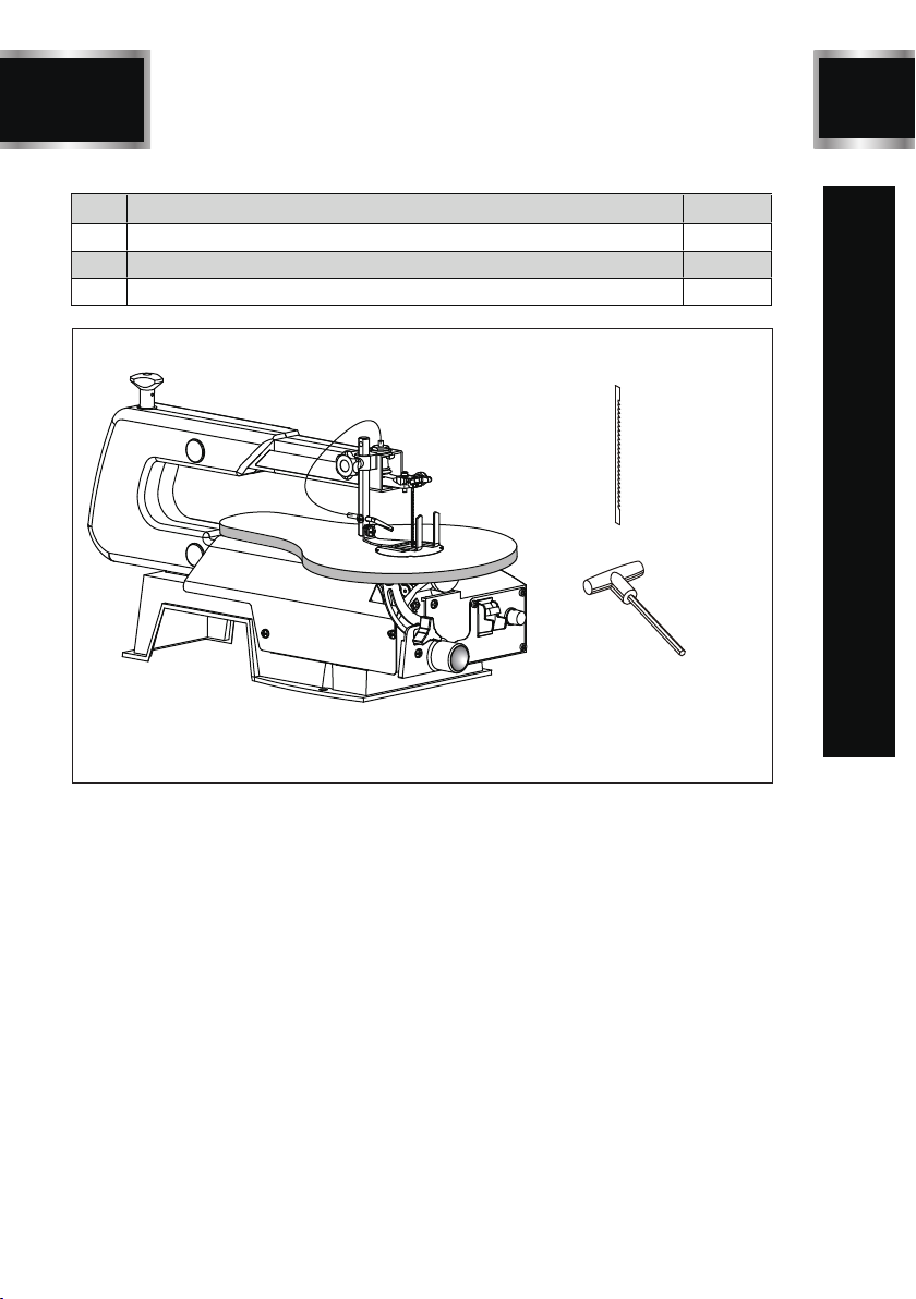
8
SSA16V
1
2
3
No. Description Qty.
1Scroll saw 1
2Blade(s) 1
3T-handle hex key 1
PACKAGE CONTENTS

BD4603
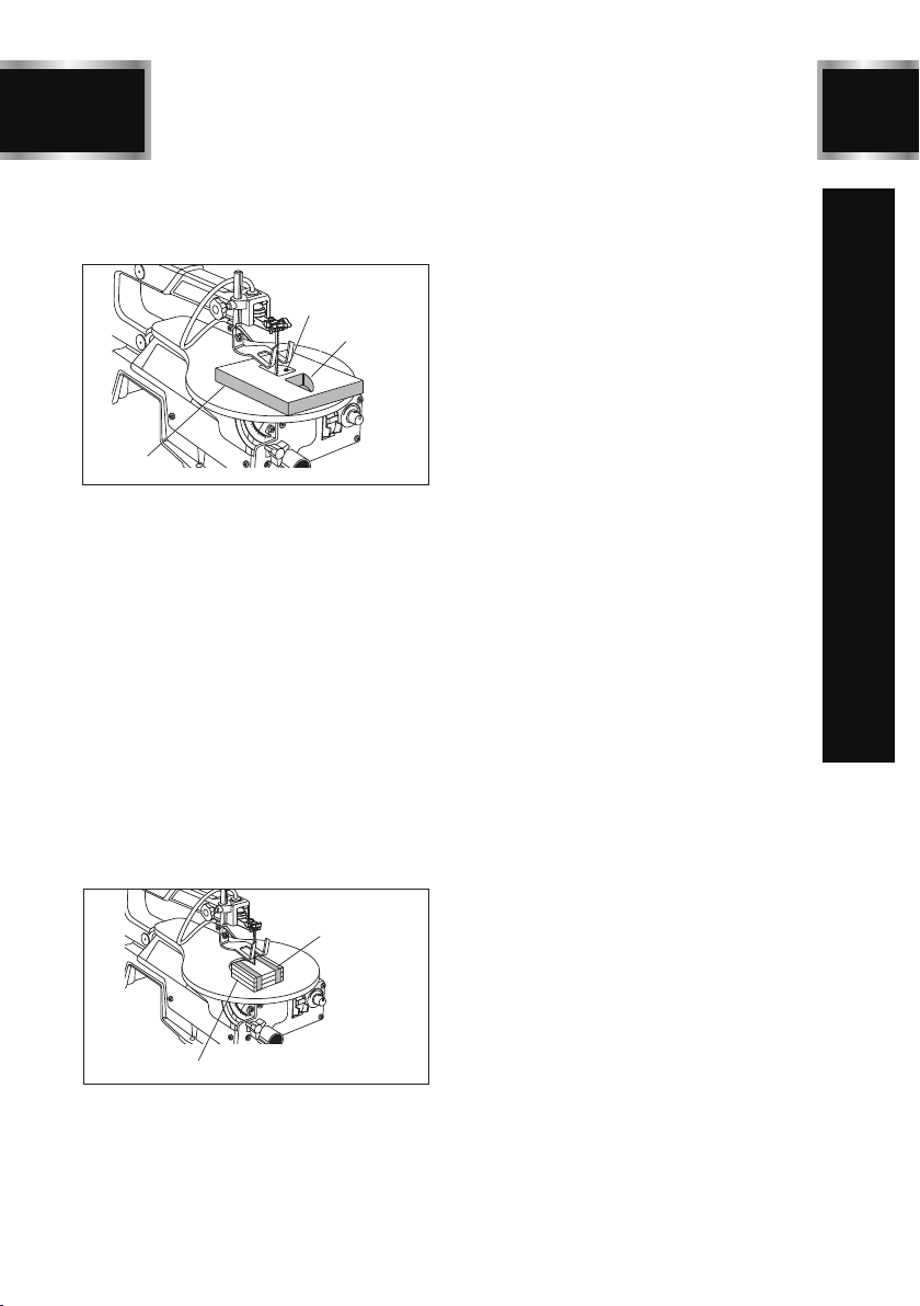
9SSA16V
KEY PARTS DIAGRAN
J
B
N
C
A
H
G
F
E
I
D
K
L
M
A - Blade tension knob
B - Drop foot lock knob
C- Saw dust blower
D- Saw blade
E - Saw table
F - Throat plate
G- Variable speed knob
H- Switch and switch key
I- Sawdust exhaust
J - Bevel lock knob
K - Bevel scale
L - Drop foot
M- Blade(s)
N- T-handle hex key

10
SSA16V
ASSEMBLY/ MOUNTING
Do not use this product if any parts on
the Loose Parts List are already asse-
mbled to your product when you unpack
it. Parts on this list are not assembled
to the product by the manufacturer and
require customer installation.Use of a
product that may have been improperly
assembled could result in serious per-
sonal injury.
MOUNTING SCROLL SAW TO WORKBENCH
If the scroll saw is to be used in a permanent appli-
cation, we recommend that you secure it in a
permanent location such as a workbench. When
mounting the saw to a workbench, holes should
be drilled through the supporting surface of the
workbench.
Each hole in the base of the saw should be bolted
securely using machine bolts, washers, and nuts
(not included). Bolts should be of sufficient length
to accommodate the saw base,washers,nuts, and
the thickness of the workbench.
Place scroll saw on workbench. Using the saw
base as a pattern, locate and mark the holes
where the scroll saw is to be mounted.
Drill four holes through the workbench.
Place scroll saw on workbench aligning holes in
the saw base with the holes drilled in the wor-
kbench.
Insert all four bolts (not included) and tighten
securely with washers and nuts (not included).
●
●
●
●
NOTE: All bolts should be inserted from the top.
Install the washers and nuts from the underside
of the bench.
Supporting surface where scroll saw is mounted
should be examined carefully after mounting to
insure that no movement during use can result.
If any tipping or walking is noted, secure workbe-
nch or supporting surface before beginning cutting
operations.
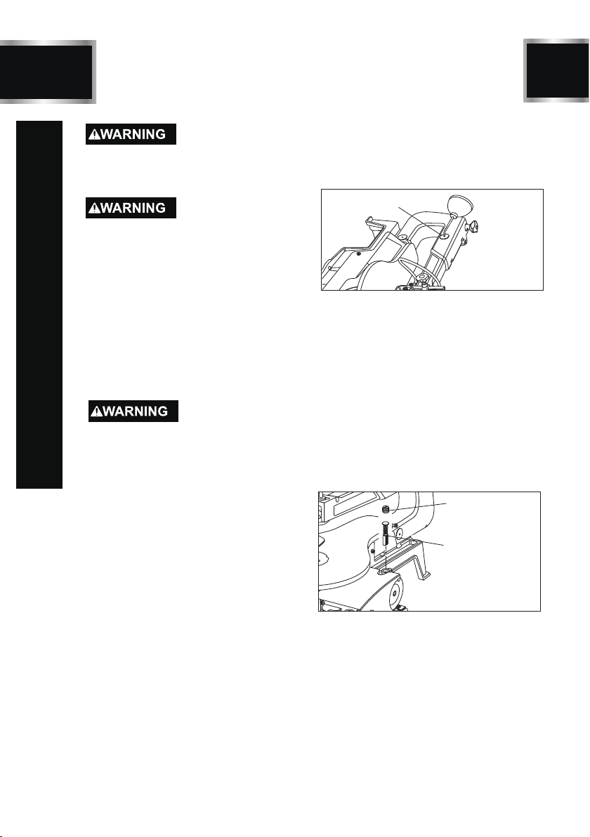
CLAMPING SCROLL SAW TO WORKBENCH
(In Figure 2)
If the scroll saw is to be used in aportable appli-
cation, it is recommended that you fasten it perma-
nently to a mounting board that can easily be cla-
Mount saw to board using holes in saw base as a
template for hole pattern. Locate and mark the
holes where scroll saw is to be mounted.
Follow last three steps in previous section called
“Mounting Scroll Saw to Workbench”.
If lag bolts are being used, make sure they are long
enough to go through holes in the saw base and
the material the saw is being mounted to.
If machine bolts are being used, make sure they
are long enough to go through holes in the saw
base,the material the saw is being mounted to,and
the washers and nuts.
mped to a workbench or other supporting surface.
The mounting board should be of sufficient size to
avoid tipping of saw while in use. Any good grade
plywood or chipboard with a 3/4 in. thickness is re-
commended.
4.Mounting board
1.
2.Saw base
3. Workbench
C-clamp
1.C-clamp
Figure2
SAWDUST BLOWER(In Figure3)
●
The sawdust blower is designed and preset to
direct air to the most effective point on the cutting
line. Be sure drop foot is properly adjusted to
secure workpiece and direct air to the cutting
surface.
Plastic tubing should be connected to the bellows
tube before starting the saw.
3. Bellows tube
1. Sawdust blower
2. Plastic
tubing
4. Drop foot
5.Drop foot lock knob
Figure3

11
ASSEMBLY/ MOUNTING
SSA16V
DROP FOOT (In Figure 3)
To prevent workpiece from lifting, the drop
foot should be adjusted so it just rests on the
top of the workpiece. The drop foot should
not be adjusted so that the workpiece drags.
Always retighten the drop foot lock knob after
each adjustment has been made.
The tall, front part of the drop foot acts as a
blade guard to prevent accidental contact
with the blade.
Loosen the drop foot lock knob.
Lower or raise the drop foot to the desired
position.
Retighten the drop foot lock knob.
●
●
●
SQUARING THE SAW TABLE TO THE BLADE
(In Figure 4-5)
2.Drop foot
3.Drop foot rod
5. Table lock knob
1.Drop foot
lock knob
4.
Combination
square
Figure4
Loosen the drop foot lock knob and move
drop foot rod all the way up. Retighten drop
foot lock knob.
Loosen the table lock knob to tilt the saw
table until it is approximately perpendicular
or at right angle to the blade.
Place a small square on the saw table next
to the blade.
Loosen the screw holding the scale indicator.
Move indicator to the 0° mark and securely
tighten screw. Remember, the bevel scale
is a convenient guide but should not be relied
upon for precision. Make practice cuts on
scrap material to determine if your angle
settings are correct.
Adjust the drop foot to desired position and
securely retighten the drop foot lock knob.
●
●
●
●
●
45
30
15
0
ON
OFF
1. Bevel
scale
2. Scale
indicator
3. Table lock knob
4. Screw
Figure5
A bevel scale is located under the saw table
as a convenient guide for setting the app-
roximate saw table angle for bevel cutting.
When greater precision is required, make
practice cuts on scrap material and adjust
the saw table as necessary for your requi-
rements.
SETTING THE TABLE FOR HORIZONTAL
OR BEVEL CUTTING(In Figure 5)
NOTE: When cutting at angles, the drop foot
should be tilted so it is parallel to the saw
table and rests flat against the workpiece.
To tilt the drop foot, loosen phillips screw,
tilt drop foot to the proper angle, then ret-
ighten screw.
Loosen the drop foot lock knob.
Center the drop foot around the saw blade
to the desired position.
Tighten the drop foot lock knob.
●
●
●
ADJUSTING BLADE TENSION(In Figure 6)
1.To tighten
(pour serrer, para
apretar)
Blade tension knob
To loosen
Figure6
Turning the blade tension knob counterclo-
ckwise decreases (or loosens) blade tension.
Turning the blade tension knob clockwise
increases (or tightens) blade tension.
●
●

12
SSA16V
ASSEMBLY/ MOUNTING
NOTE: Adjustments to blade tension can be
made at any time.Check tension by the sound
the blade makes when plucked like a guitar
string. This method of adding tension to the blade
can be developed with practice and requires
knowing the scroll saw.
Pluck the back straight edge of blade while turning
tension adjusting knob. Sound should be a
musical note.Sound becomes less flat as tension
increases. Sound decreases with too much tension.
●
NOTE: Be careful not to adjust blade too tight.
Too much tension may cause the blade to break as
soon as you start cutting. Too little tension may
cause the blade to bend or break before the teeth
wear out.

BD4603
13
OPERATION
SSA16V
Do not allow familiarity with products to make
you careless. Remember that a careless fra-
ction of a second is sufficient to inflict serious
injury.
Always wear eye protection with side shields
marked to comply with ANSI Z87.1. Failure to do
so could result in objects being thrown into your
eyes, resulting in possible serious injury.
Do not use any attachments or accessories not
recommended by the manufacturer of this prod-
uct. The use of attachments or accessories not
recommended can result in serious personal
injury.
APPLICATIONS
You may use this product for the following
purposes:
Cutting wood, wood composition products,
plastic, and other fibrous material up to 2 in.
thick
●
BASIC OPERATION OF THE SCROLL SAW
Before starting a cut, watch the saw run.If you
experience excessive vibration or unusual noise,
stop immediately.Turn the saw off ,remove the
switch key, and unplug the saw. Do not restart
until locating and correcting the problem.
NOTE: After the saw is turned ON, a hesitation
before blade movement is normal.
CUTTING PROCEDURES
There is a learning curve for each person who
wants to use this saw. During that period of
time it is expected that some blades will break
until you learn how to use and adjust the saw.
Plan the way you will hold the workpiece from
start to finish.
Keep your hands away from the blade.Do not
hand hold pieces so small your fingers will
go under the blade guard.
Hold the workpiece firmly against the saw
table.
●
●
●
●
The blade teeth cut material only on the down
stroke.
Use gentle pressure and both hands when
feeding the work into the blade. Do not force
the work.
Guide the workpiece into the blade slowly be-
cause the teeth of the blade are very small and
can only remove material on the down stroke.
●
●
●
Avoid awkward operations and hand positions
where a sudden slip could cause serious injury
from contact with the blade. Never place hands
in blade path.
To get accurate cuts,compensate for the blade’s
tendency to follow the wood grain as you are
cutting wood.
Use extra supports (tables, saw horses, blocks,
etc.) when cutting large, small or awkward wor-
kpieces.
Never use another person as a substitute for
a table extension or as additional support for
a workpiece that is longer or wider than the
basic saw table.
When cutting irregularly shaped workpieces,
plan your work so it will not pinch the blade.
Workpieces must not twist, rock or slip while
being cut.
●
●
●
●
●
REMOVING JAMMED MATERIAL
When backing out the workpiece, the blade may
bind in the kerf (cut). This is usually caused by
sawdust clogging the kerf or when the blade
comes out of the blade holders. If this happens:
Wait until the saw has come to a full and co-
mplete stop.
Place the switch in the OFF position, remove
the switch key from the switch assembly.Store
key in a safe place.
Unplug the saw from the power source.
Remove the saw blade and the workpiece, see
section on Installing and Removing the Blades.
Wedge the kerf open with a flat screwdriver or
wooden wedge then remove the blade from the
workpiece.
●
●
●
●
Before removing loose or jammed pieces from the
table, turn saw off and wait for all moving parts to
stop to avoid serious personal injury.

14
SSA16V
OPERATION
AVOIDING INJURY
Make sure saw is level and does not rock. Saw
should always be on a firm, level surface with
plenty of room for handling and properly sup-
porting the workpiece.
Bolt saw to the support surface to prevent slip-
ping, walking or sliding during operations like
cutting long, heavy boards.
Turn saw off, remove switch key, and unplug
cord from the power source before moving the
saw.
Do not remove jammed cutoff pieces until blade
has come to a full and complete stop.
Choose the right size and style blade for the
material and type of cut you plan to do.
Use only recommended accessories.
With the exception of the workpiece and related
support devices, clear everything off the saw
table before turning the saw on.
Properly support round materials such as dowel
rods or tubing because they have a tendency
to roll during a cut causing the blade to “bite.”
To avoid this, always use a “V” block or clamp
workpiece to a miter gauge.
Before removing loose pieces from the saw table,
turn saw off and wait for all moving parts to stop.
●
●
●
●
●
●
●
●
●
●
LOCKING THE SWITCH(In Figure 7)
Wait until the saw has come to a full and co-
mplete stop.
Place the switch in the OFF position, then remove
the switch key from the switch assembly. Store
key in a safe place.
●
●
Switch on
Switch off
Switch key removed
Figure7
INSTALLING AND REMOVING BLADES
(In Figure 8)
Scroll saw blades wear out quickly and must be
replaced frequently for best cutting results. Ex-
pect to break some blades while you learn to
use and adjust the saw. Blades generally stay
sharp for 1/2 hour to 2 hours of cutting, dep-
ending on the type of material and speed of
operation.
Throat plate
Drop foot lock knob
Blade clamp screw
Blade clamp screw
Saw blade
Saw blade
Figure8
REMOVING THE SAW BLADE
Turn off and unplug the saw from the power
source.
Turn blade tension knob counterclockwise to
decrease (or loosen) blade tension.
Pushing up from under the saw table, remove
the throat plate.
Loosen both the upper and lower blade clamp
screws.
Pull up on the blade and push down on the saw
arm to disengage the upper pin in the V-notch
of the upper blade holder. Push the blade do-
wnward to disengage the lower pin in the V-
notch of the lower blade holder.
Remove the blade.
●
●
●
●
●
●
PIN END BLADES
Turn off and unplug the saw from the power
source.
Remove the blade.
Place the new blade through the opening in
the saw table with the teeth to the front of the
saw and pointing down toward the saw table.
The pins on the blade go under the blade holder
in the V-notch of the lower blade holder.
Pull up on the blade and press the upper arm
down to position the upper end of the blade in
the V-notch in the upper blade holder.
Securely tighten the upper and lower blade
clamps by tightening the blade clamp screws.
●
●
●
●
●
●

BD4603
15
OPERATION
SSA16V
NOTE: If the blade touches the drop foot on either
side then the drop foot must be adjusted. See se-
ction on “Drop Foot.”
Turn the blade tension knob clockwise until the
blade has the desired amount of tension.
Replace the throat plate.
●
●
PLAIN END BLADES
Turn off and unplug the saw from the power
source.
Remove the blade.
Place the new blade through the opening in the
saw table with the teeth to the front of the saw
and pointing down toward the saw table.
Position blade in the lower blade holder and
tighten the blade clamp screw securely.
Press the upper arm down to position the upper
end of the blade in the upper blade holder.
Securely tighten the upper blade clamp screw.
Turn the blade tension knob clockwise until the
blade has the desired amount of tension.
Replace the throat plate.
●
●
●
●
●
●
●
NOTE:If the blade touches the drop foot on either
side then the drop foot must be adjusted. See
section Drop Foot.
BLADE INFORMATION
Scroll saw blades wear out and must be repla-
ced frequently for best cutting results. Scroll
saw blades generally stay sharp for 1/2 hour to
2 hours of cutting, depending on type of ma-
terial and speed of operation.
In cutting wood, best results are achieved when
cutting wood less than one inch thick.
When cutting wood thicker than one inch, the
user must guide the workpiece very slowly into
the blade and take extra care not to bend or
twist the blade while cutting.
When choosing a blade, carefully consider the
following:
1)Very fine, narrow blades should be used to
scroll cut in thin material 1/4 in. thick or less.
2)Most blade packages state the size or thic-
kness and type of material which that blade is
intended to cut.The package should also state
the radius or size of curve that can be cut with
that blade size.
3)Wider blades cannot cut curves as tight or
as small as thinner blades.
●
●
●
●
●
Blades wear faster when:
1)Cutting plywood, hardwood, and other la-
minates.
2)Cutting material thicker than 3/4 in.
3)Side pressure is applied to the blade.
●
CHOICE OF BLADE AND SPEED
The scroll saw accepts a wide variety of blade wi-
dths and thicknesses for cutting wood and other
fibrous materials. The saw uses 5 in. long blades
of either the pin end or the plain end style.The blade
width and thickness and the number of teeth per
inch to use are determined by the type of material
and the size of the radius being cut.
Teeth/Inch Width Thickness Speed or
Strokes Per Minute
Material Cut
10 .110 in. .020 in. 1,200 - 1,600
15 .110 in. .020 in. 600 - 1,200
18 .095 in. .010 in. 550 - 600
Popular size for cutting
hard and soft woods 3/16
in. up to 2 in. Plastics,
paper, felt, bone, etc.
Wood,plastics, extremely
thin cuts on materials 3/32
in.to 1/2 in. thick.
For tight radius work in
thin materials 3/32 in. to
1/8 in. Wood, veneer,bone,
fiber, ivory, plastic, etc.
USING VARIABLE SPEED(In Figure 9)
45
30
15
0
ON
OFF
1.Variable speed knob
2.To increase
(pour augmenter,
para aumentar)
3.To decrease
(pour réduire, para
disminuir)
By turning the variable speed knob, the saw’s
speed may be adjusted from a high speed of
approximately 1,650 SPM (Strokes Per Minute)
to a low speed of approximately 550 SPM.
To increase the strokes per minute, turn the va-
riable speed knob clockwise or to the right.
To decrease the strokes per minute,turn the va-
riable speed knob counterclockwise or to the left.
●
●
●
Figure9
SCROLL CUTTING
For general type scroll cutting, follow the pattern
lines by pushing and turning the workpiece at the
same time. Do not try to turn the workpiece while
16
BD4603
3. Workpiece
1.Arm bearing
INTERIOR SCROLL CUTTING(In Figure 10)
engaged in the blade without pushing it – the
workpiece could bind or twist the blade.
SSA16V
0
30
15
L
1.
Drill hole
(percer un trou, taladrar
agujero)
Figure10
2.Interior cut
One feature of a scroll saw is that it can be used
to make scroll cuts on the interior of a workp-
iece without breaking or cutting through the
edge or perimeter of the board.
To make interior cuts in the workpiece,remove
the scroll saw blade as explained in the section
on Installing and Removing Blades.
Drill a 1/4 in. hole in the workpiece.
Place the workpiece on the saw table with the
drilled hole over the access hole in the table.
Install blade through the hole in the workpiece;
adjust the drop foot and blade tension.
When finished making the interior scroll cuts,
simply remove the blade from the blade hold-
ers as described in the section on Installing
and Removing Blades and remove the work-
piece from the saw table.
●
●
●
●
●
●
STACK CUTTING(in Figure 11)
0
30
15
L
2.lMotor brush Figure11
After becoming well acquainted with the saw
through practice and experience, you may
wish to try stack cutting. Stack cutting may
be used when several identical shapes need
to be cut. Several pieces of wood may be st-
acked on top and secured to each other before
cutting. The wood pieces may be joined to-
gether by placing double sided tape between
each piece or by wrapping masking tape
around the corners or ends of the stacked
wood. You must attach the stacked pieces
of wood to each other so they will move on
the table as a single piece of material.
OPERATION
BD4603
17
MAINTENANCE
SSA16V
When servicing, use only identical replace-
ment parts. Use of any other parts can create
a hazard or cause product damage.
Always wear eye protection with side shields
marked to comply with ANSI Z87.1. Failure
to do so could result in objects being thrown
into your eyes, resulting in possible serious
injury.
GENERAL MAINTENANCE
Avoid using solvents when cleaning plastic
parts. Most plastics are susceptible to dam-
age from various types of commercial solvents
and may be damaged by their use. Use clean
cloths to remove dirt, dust, oil, grease, etc.
Do not at any time let brake fluids, gasoline,
petroleum-based products, penetrating oils,etc.,
come in contact with plastic parts. Chemicals
can damage, weaken, or destroy plastic which
could result in serious personal injury.
Keep the saw clean.
After cleaning the table top initially, apply a
thin coat of automobile type (paste) wax to
the table top so the wood slides easily while
cutting.
Do not allow pitch to accumulate on the saw
table. Clean with gum and pitch remover. Do
not use gasoline.
●
●
●
Electric tools used on fiberglass material, wa-
llboard, spackling compounds, or plaster are su-
bject to accelerated wear and possible prem-
ature failure because the fiberglass chips and
grindings are highly abrasive to bearings, brushes,
commutators, etc. Consequently, we do not
recommended using this product for extended
work on these types of materials. However, if
you do work with any of these materials, it is
extremely important to clean the product using
compressed air
ARM BEARINGS(In Figure 12)
Lubricate the arm bearings after the first 10
hours of use. Oil after every 50 hours of use
or whenever there is a squeak coming from
the bearings.
0
30
15
L
Figure12
1.Arm bearing
(roulement du bras,
cojinete del brazo)
Carefully place the saw on its side as shown.
Remove the rubber cap from the upper and
the lower arm of the saw.
Squirt a few drops of SAE20 oil around the
shaft end and arm bearings. Let oil soak in
overnight, remaining in this position.
●
●
NOTE: Lubricate the bearings on the other side
of the saw in this same manner.
MOTOR BRUSHES(In Figure 13)
The saw has externally accessible motor brush
assemblies that should be checked periodically
for wear. When one of the two brushes becomes
worn, replace both brushes.
Unplug the saw from the power source.
Carefully place the saw on its side exposing
the underside of the saw housing.
Using aflat blade screwdriver,remove the bottom
brush assembly cap through the access hole
in the base and the top brush assembly cap
from the top of the motor. Gently pry the brush
assemblies out using a small screwdriver, point
of a nail, or paper clip.
If one motor brush is worn down shorter than
1/4 in. (6 mm), replace both motor brushes.
Figure13
2.Motor brush
(charbon de moteur,
escobilla del motor)
1.Brush cap (bouchon
de porte-charbon, tapa
de la escobilla)
●
●
●
●

18
Problem Likely Solutions
Motor will not run
Blades breaking
Vibration
(there is always some
vibration when the
saw is running)
Problem Possible Causes Likely Solutions
SSA16V
TROUBLESHOOTING
Problem with ON-OFF switch,
power cord, or outlet.
Motor defective.
Have worn parts replaced before using scroll saw
again. Have the proper outlet installed by a qualified
electrician.
Do not attempt any repair. Have repaired by a
qualified service technician.
Too much tension.
Feeding too quickly.
Wrong blade.
Blade twisting in wood.
Adjust tension.
Reduce feed rate.
Narrow blades for cutting thin wood or tight corners
and turns, wide blades for thicker wood or wide turns.
Reduce side pressure on blade; check blade tension.
Improper mounting of saw.
Mounting surface.
Loose table or table resting
against motor.
Loose motor mounting.
Check mounting.
Check mounting in manual.
Tighten table lock knob.
Tighten mounting screws.
Blade runout
(blade not properly
aligned with arm
motion)
Blade holders out of line. Realign blade.

EXPLODED VIEW
BD4603
19 SSA16V

20
BD4603
SSA16V
PARTS LIST
Hose
57 Big flat washer Washer 6
58 Compression spring 65Mn 1
Item Description Specification Qty
Item Description Specification Qty
1 Philips Screw M5X8 2
41 Eccentric connector plate Q235 1
2 Handle ABS 1
42 Philps screw ST4.2X9.5 5
3 Side Cover Q235 1
43 Small spacer Powder metal 1
4 Hex nut, I type M6 5
44 Hex screw+spring washer M5X16 1
5 Spring washer Washer 6 4
45 L wrench S3 1
bonkratS64
1051THesaB6
7 Dust cap NR 4
47 Drop foot guide post 45 1
8 Left Arm housing ZL105 1
48 Philips Screw+spring washer M5X30 2
9 Tension lever assembly 1
49 Circuit Board E 1
toofporD05
1nM56gnirpS01
rehsawtalF15
2etalP11
12 Spring washer Washer 4 1
52 Philips Screw+spring washer M6X10 1
13 Hex screw+spring washer M4X10 2
53
14 Lower Arm ZL105 1
54 PVC bushing Washer 6 1
15 Upper Arm ZL105 1
55 Hex screw M6X40 1
hsawgnirps+tlobxeH65
4gniraebeveelsliO61
17 Air Nozzle Q235 1
18 Philips Screw M5X6 1
19 Right Arm housing ZL105 1
59 Hex screw M6X
20 Spring washer Washer 5 2
60 Table Mounting Bracket HT150 1
retnioP16
553X5Mrehsawgnirps+wercSspilihP12
22 Spring Washer 5 1
62 Miter Gauge Q235 1
23 Bellow Cover ABS 1
63 Work Table ZL105 1
24 Philips Screw+spring washer M5X28 1
64 Table insert ABS 1
25 Locking knob ABS 1
65 Variable speed Knob ABS 1
26 Switch box cover ABS 1
66 Hex screw M5x6 1
drocrewoP76
17YHhctiwS72
awtalf+wercSspilihP86
1RNwolleB82
29 Mounting Plate Q235 2
69 Hex screw M8X12 1
30 Carriage screw M6X20 4
70 Eccentric counter wheel Powder metal 1
rotoM17
1troppusedalBreppU13
32 Locking washer Washer 4 4
72 Switch Box ABS 1
33 Hex Screw M4X16 2
73 Cord Clip 6P-4(certificate) 1
1 Philips Screw M5X8 2 41 Eccentric connector plate Q235 1
2 Handle ABS 1 42 Philps screw ST4.2X9.5 5
3 Side Cover Q235 1 43 Small spacer Powder metal 1
4 Hex nut, I type M6 5 44 Hex screw+spring washer M5X16 1
5 Spring washer Washer 6 4 45 L wrench S3 1
HesaB6
7 Dust cap NR 4 47 Drop foot guide post 45 1
8 Left Arm housing ZL105 1 48 Philips Screw+spring washer M5X30 2
9 Tension lever assembly 1 49 Circuit Board E 1
gnirpS01
etalP11
12 Spring washer Washer 4 1 52 Philips Screw+spring washer M6X10 1
13 Hex screw+spring washer M4X10 2 53
14 Lower Arm ZL105 1 54 PVC bushing Washer 6 1
15 Upper Arm ZL105 1 55 Hex screw M6X40 1
gniraebeveelsliO61
Air Nozzle Q235
Philips Screw M5X6
19 Right Arm housing ZL105 1 59 Hex screw M6X
20 Spring washer Washer 5 2 60 Table Mounting Bracket HT150 1
rehsawg
nirps+wercSspilihP12
23 Bellow Cover ABS 1 63 Work Table ZL105 1
24 Philips Screw+spring washer M5X28 1 64 Table insert ABS 1
25 Locking knob ABS 1 65 Variable speed Knob ABS 1
Table of contents
Popular Saw manuals by other brands


Makita
Makita MLS100 instruction manual

Crown
Crown CT15228-110-W Original instructions

Villager
Villager VMS 18020 Original instruction manual

AM TECH
AM TECH Y0200 Instruction manual and safety guide

Scheppach
Scheppach HM254SPX Translation of original instruction manual

DBK
DBK ES 185 C operating instructions