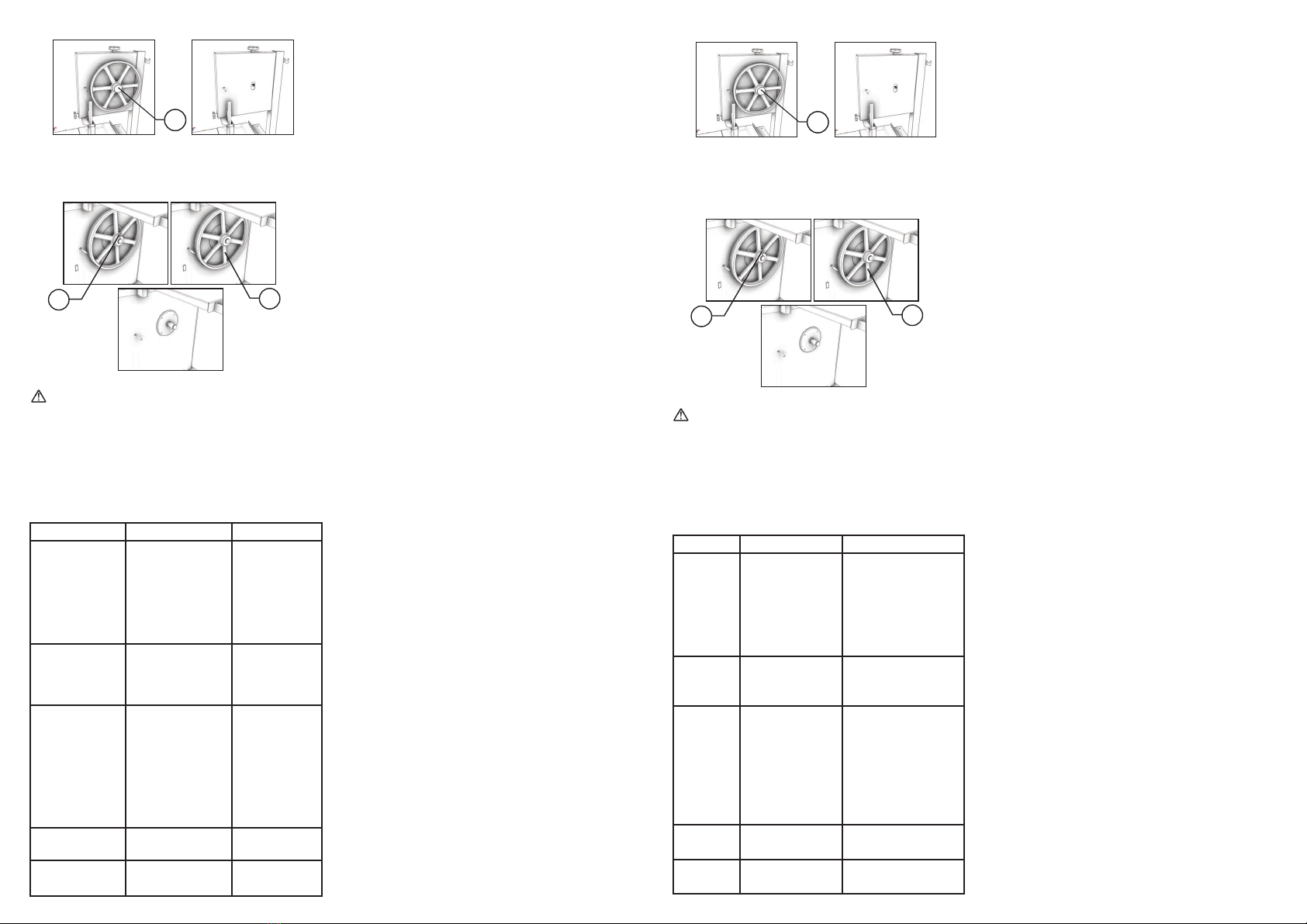
- Volante Inferior
Rere la Presilla No. 01 (Fig.09) , agarre firmemente el
Volante Inferior No.02 (Fig.09) y relo para la frente de la
maquina, vea la Figura 09.
Lave todas las partes con agua y jabón neutro.
No use chorros de agua directamente sobre la maquina.
Use un paño limpio ó un cepillo blando para remover
residuos impregnados.
Lave, higienice, enjuague y seque todas las partes..
Monte de vuelta todos los componentes de la maquina en
el orden inverso al del desmontaje , averiguando que todos
estén correctamente montados.
6. RESOLUCIÓN DE PROBLEMAS
7. MAINTENANCE
El mantenimiento debe ser considerado como un conjunto
de procedimientos con el objevo de conservar el equipo en
las mejores condiciones de funcionamiento propiciando un
aumento de su vida úl y de su seguridad.
* Limpieza verificar el ítem No. 5 de este manual .
* Cableado - verifique todos los cables cuanto a su
deterioración y todos los terminales cuanto a su aprieto y
corrosión.
* Contactos – Llave prende/desliga, botón de emergencia,
botón rearme, circuitos electrónicos, etc Verifique el
equipo para que todos los componentes estén funcionando
correctamente , y que la operación del equipo sea normal .
* Instalación – Verifique la instalación de su equipo de
acuerdo con el ítem 3.2 de este manual.
* Vida ul del producto – 2 años para un turno normal de
trabajo.
1. verificaciones a ejecutar mensualmente:
- Verificar la instalación eléctrica.
- Controlar la tensión de la toma eléctrica.
- Medir la corriente eléctrica y compararla con la corriente
nominal.
- Verificar el aprieto de todos los terminales eléctricos para
evitar malos contactos.
- Verificar posibles holguras del eje del motor eléctrico
- Controlar el cableado eléctrico para idenficar señales
de sobrecalentamiento, aislamiento deficiente o avería
mecánica.
2. verificaciones a ejecutar cada tres meses:
- Verificar los componentes eléctricos como la llave prende/
desliga, botón de emergencia, botón rearme, y circuitos
electrónicos con respecto a sobrecalentamiento, aislamiento
deficiente o avería mecánica .
-Verificar posibles holguras en los ejes y rodamientos.
- Verificar retenedores, anillos O’ring , anillos V’ring, y otros
sistemas de vedamiento
FIGURA 08
01 02
FIGURA 09
01
PROBLEMAS CAUSES SOLUTIONS
-La maquina no
se prende
-Falta de Energía
Eléctrica
-Problema con el
circuito Interno
o externo de la
maquina.
-Averigüe si hay
energía eléctrica
-Llame el
Servicio Técnico
-Ejecute el ítem
3.1
-Olor de
quemado o
humo
-Problema con el
circuito Interno
o externo de la
maquina
-Llame el
Servicio Técnico
-La maquina
se prende,
pero cuando el
producto entra
en contacto con
la Hoja , la misma
para o gira en
baja Rotación
-Correa panando
-Problemas con el
motor
-Hoja con mala
tensión
-Llame el
Servicio Técnico
-Llame el
Servicio Técnico
-Llame el
Servicio Técnico
-Ruidos
anormales
-Rodamiento
dañado.
-Llame el
Servicio Técnico
-Cable Eléctrico
dañado
-Problema durante
el transporte.
-Llame el
Servicio Técnico
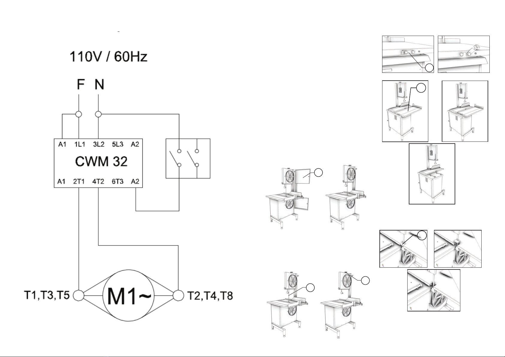
- Lower Wheel
Remove the Staple #01 (Pic. 09) grab strongly the Lower
Wheel #02 (Pic. 09) and pull it to the front side of the
equipment, see picture 09.
Wash all the components with water and neutral soap.
Do not spray water directly on the equipment.
Use a clean cloth or a sobrush to remove residues.
Wash, sanize, rinse and dry all the components.
Assemble back all the components following the inverse
path , and make sure all the components are correctly in
place.
6. PROBLEMS SOLUTIONS
7. MAINTENANCE
Maintenance must be considered a set of procedures
with the purpose to keep the equipment best operang
condions, therefore increasing the equipment life and
safety.
* Cleaning – check item 5. CLEANING.
* Wiring - Check all wires regarding deteriorate condions as
well as all electric contacts (terminals) regarding ghtening
and corrosion .
*Contacts – ON/OFF switch, emergency buon, reset
buon, electronic circuits etc , check the equipment in order
to assure that all components are correctly working and the
equipment operaon is normal .
* Installaon – make sure the installaon followed item 3.2
instrucons.
* Useful life of the product: 2 years, for a normal working
shi.
1 – Each month check :
- Check the electrical installaon
- Measure the voltage at the socket
- Measure the working current and match it with the
nominal current
- Check the ghtening of all electric terminals to avoid bad
contacts
- Check electric motor shafor possible looseness.
- Check the wiring for overheang , insulaon failures and
mechanical damages.
2 - Each three month checks:
- Check electrical components such as ON/OFF switch,
emergency buon , reset buon, electronic electric circuits ,
overeang, insulaon failings, or mechanical damages
- Check cung units and bearings for possible looseness.
- Check retainers, O’rings, V’rings and other seals.
PICTURE 08
01 02
PICTURE 09
01
PROBLEMS CAUSES SOLUTIONS
-The
equipment
does not
switch on.
-Lack of power.
-Problem with the
internal or external
circuits of the
equipment.
-Check if there is
electric power.
-Call Technical
Assistance.
-Apply item 3.1
instrucons.
-Smoke or
burn smell.
-Problem with the
internal or external
electric circuits
-Call Technical
Assistance.
-Machine
switch on
but when
product
touches
the blade
it stops or
runs slowly.
-Belt slipping on
pulleys.
-Damaged motor
-Blade is not well
stretched.
-Call Technical
Assistance.
-Call Technical
Assistance.
-Call Technical
Assistance.
-Unusual
noises. -Damaged bearing -Call Technical
Assistance.
-Damaged
Cord
-Problem during
transportaon.
-Call Technical
Assistance.