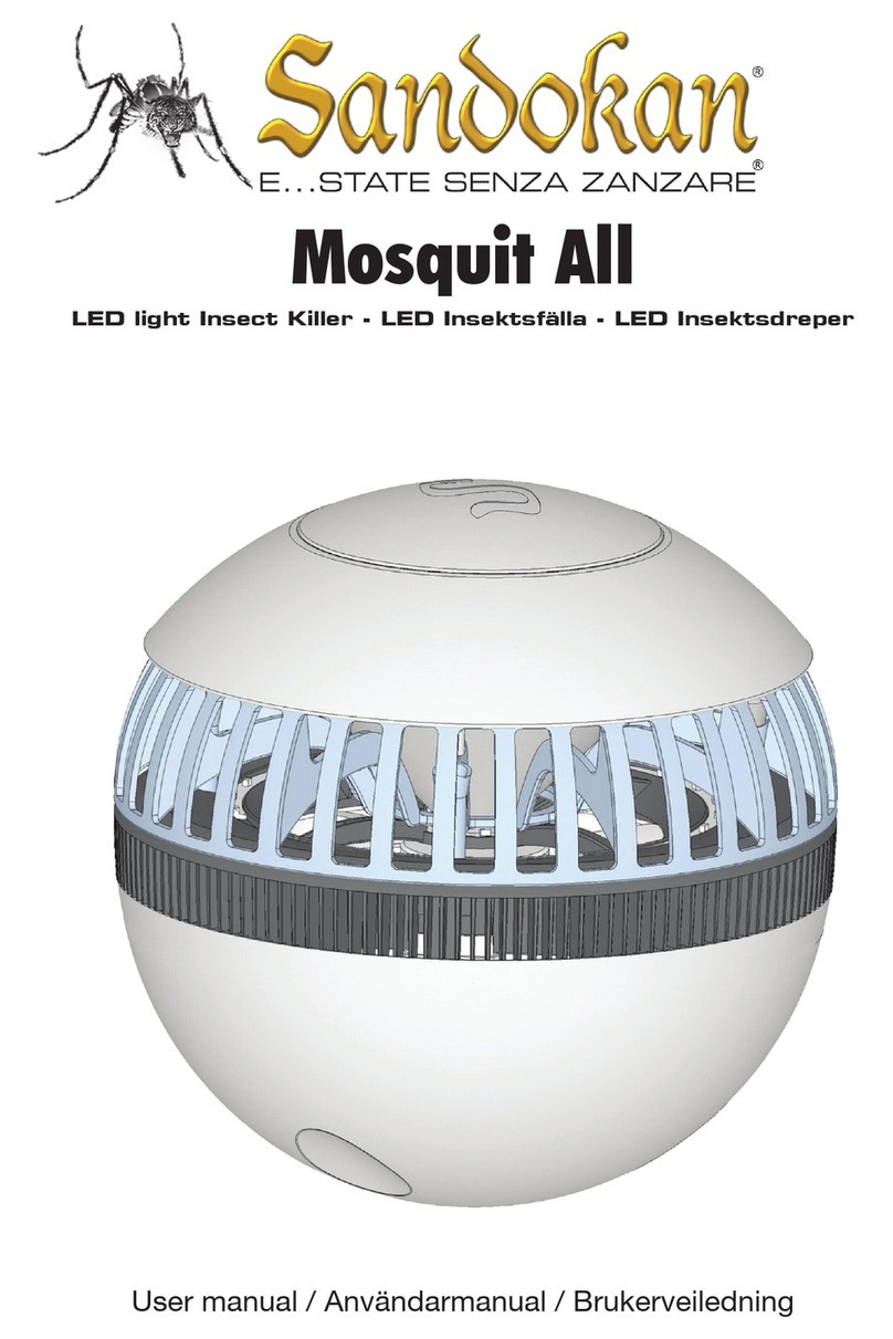
TOURNUS EQUIPEMENT 806 941 User manual

25 avenue Jean Moulin
CS 20005 - 71700 TOURNUS - FRANCE
Phone. +33 (0)3 85 27 42 56
Fax. +33 (0)3 85 27 42 50
R
ENGLISH
MANUFACTURER’S SPECIFICATIONS Ref : ML 104053
Iss : 5
INSECT KILLERS Date: 08/2015
CONTENTS
1 DATA SHEET
2 INSTALLATION
3 WIRING DIAGRAMS
4 RISKS WHEN IN USE
5 SPARE PARTS
6 MAINTENANCE - CLEANING
7 WORKING LIFE
8 SERVICING
INSTALLATION
ENGINEER’S STAMP

TECHNICAL MANUAL ENGLISH
725 avenue Jean Moulin
B.P. 59 71700 TOURNUS - FRANCE
Tél. +33 (0)3 85 27 42 56
Fax. +33 (0)3 85 27 42 50 ML 104053 Iss.5
TECHNICAL SPECIFICATIONS:
• Made completely of stainless steel
• Stainless steel wire electrocution grids and protective grid
• Power supply cable, length 1.20 m.
• Stainless steel suspension chain (for suspended model)
• Long effective life (5000 hours) actinic tubes
• Power supply voltage 230 V - 50 Hz
• Protection index: IP 21
• Complies with standard NF EN 60335-1
NF EN 60335-2-59
OPERATING PRINCIPLE
• The light source comes from the special (actinic) fluorescent tubes.
• The UV radiation attracts the insects which are electrocuted on contact with the inner grids. These are powered by a transformer
supplying high voltage at low intensity (4,000 V for 9 mA).
• The electrocuted insects fall into a removable collection tray at the bottom of the appliance.
ELECTRIC INSECT KILLERS
Suspended models
APPLIANCES FOR USE
INDOORS ONLY
Wall model
Description Reference Dimensions (mm)
l x H x W Actinitic tubes Input
power Weight (kg) Surface protected
15W suspended electric insect killer 806 941 460 x 235 x 96 1 x 15 W 40 W 4,4 40 m2
30W suspended electric insect killer 806 943 460 x 285 x 111 2 x 15 W 50 W 4,9 80 m2
40W suspended electric insect killer 806 945 615 x 330 x 111 2 x 20 W 63 W 6,2 90 m2
80W suspended electric insect killer 806 947 615 x 330 x 111 2 x 40 W 98 W 6,8 180 m2
Description Reference Dimensions (mm)
l x H x W Actinitic tubes Input
power Weight (kg) Surface protected
40W wall electric insect killer 806 952 615 x 240 x 96 1 x 40 W 53 W 5,6 50 m2
W

TECHNICAL MANUAL ENGLISH
825 avenue Jean Moulin
B.P. 59 71700 TOURNUS - FRANCE
Tél. +33 (0)3 85 27 42 56
Fax. +33 (0)3 85 27 42 50 ML 104053 Iss.5
TECHNICAL SPECIFICATIONS:
• Made completely of food quality stainless steel
• Glue plate
• Power supply cable, length 1.20 m
• Stainless steel suspension chain (for suspended model)
• Complies with standard NF EN 60335-1
NF EN 60335-2-59
• Long effective life (5000 hours) actinic neon tubes
• Power supply voltage 230 V - 50 Hz
• Protection index: IP 21
OPERATING PRINCIPLE
• The light source comes from the special (actinic)
fluorescent tubes.
• The UV radiation attracts the insects which then get stuck
on a plate of glue.
Suspended
model
side
view
Wall
model
side
view
GLUE INSECT KILLERS
806 967 806 960
Désignations Références Dimensions (mm)
l x H x L
Tubes
actinitiques
Puissance
absorbée Poids (kg) Surface protégée
Désinsectiseur suspendu à glu 80W 806 967 615 x 285 x 142 2 x 40 W 98 W 5,5 180 m2
Désinsectiseur mural à glu 40W 806 960 615 x 285 x 97 1 x 40 W 53 W 4,6 50 m2

TECHNICAL MANUAL ENGLISH
925 avenue Jean Moulin
B.P. 59 71700 TOURNUS - FRANCE
Tél. +33 (0)3 85 27 42 56
Fax. +33 (0)3 85 27 42 50 ML 104053 Iss.5
INSTALLATION
Place :
The insect killers should be fixed to a wall or hung, about two meters from the floor, away from sunlight and sources of light.
Make sure that the insect killers is placed between the insects entry point into the room and the area you want to protect.
Electric insect killers should not be used in premises or sites there are inflammable fumes or explosive dust. They should not be used in
barns, stables or similar places either.
siting example :
As each case is different, here is a diagram to illustrate the
positioning procedure.
Insect killers
Insect entry point
Electric connection :
The surface socket to which the insect killers will be connected
must be protected by a 15 mA differential circuit breaker and have an omnipolar cutout device.
This socket must be earthed.
WIRING DIAGRAMS
WIRING DIAGRAM model 806 947
ELECTRIC INSECT KILLERS
Supply cord
transformer
PRI 220/240 V 50 Hz
SEC : 4000 V 7-9 mA
BALLAST
Actinic tubes
(starters not
shown)
Electrified grid
Supply cord
transformer
PRI 220/240 V 50 Hz
SEC : 4000 V 7-9 mA
BALLAST
Actinic tubes
(starters not
shown)
Electrified grid
BALLAST
Supply cord
BALLAST
Actinic tubes
(starters not
shown)
Supply cord
BALLAST BALLAST
Actinic tubes
(starters not
shown)
INSECT KILLERS LIME
WIRING DIAGRAM (except model 806 947)
Model 806 960 Model 806 967
AREA TO PROTECT

TECHNICAL MANUAL ENGLISH
10 25 avenue Jean Moulin
B.P. 59 71700 TOURNUS - FRANCE
Tél. +33 (0)3 85 27 42 56
Fax. +33 (0)3 85 27 42 50 ML 104053 Iss.5
MAINTENANCE AND CLEANING
MAINTENANCE
• Do not forget to empty the retrieval container on a daily basis (electric insect killers)
• Do not forget to change the insect lime strip on a regular basis (electric insect lime)
CLEANING
Before cleaning, you must check that the insect killers is disconnected, i.e. unplugged, to avoid any risk of electrocution.
• The insect killers must be cleaned regularly using standard cleaning products in compliance with hygiene standards, but not with abrasive
products. Avoid chlorinated products (bleach for example) and rinse thoroughly after cleaning. It is recommended that you wear gloves during
cleaning operations.
SPARE PARTS
• Ballast 18 W - 230 V
• Ballast 30 W - 230 V
• Ballast 36 W - 230 V
• Actinic tube 15 W
• Actinic tube 20 W
• Actinic tube 40 W
: 229 810
: 229 811
: 229 812
: 229 800
: 229 801
: 229 802
• Starter for all models except 806 943 and 806 945
• Starter for models 806 943 and 806 945
• Transformer 4000 V - 9 mA
• Insect killers lime strip dim. 590 x 330 mm
WORKING LIFE
YOU MUST CHANGE THE LIGHTING TUBES EVERY YEAR.
After this time limit, the tubes will still work but lose most of their attractive power.
WARNING :
Servicing must be carried out by an authorized person.
Before any servicing operation, you must make sure that the insect killers is disconnected, i.e. unplugged, to avoid any risk of electrocution.
If the supply cord is damaged, it must be replaced by the manufacturer, its after-sales service or by an authorized person, in order to avoid any
type of danger.
To access the neon light or the electrocution grid, you must take off one of the safety grids by removing the 4 screws that secure it.
To access the ballast, the tie-point block or the transformer, just remove the top cover which is also secured by 4 screws.
SERVICING
RISKS WHEN IN USE
Never use the insect killers without the safety grids.
: 262 100
: 262 099
: 262 484
: 807 080
This manual suits for next models
6
Table of contents
