TourPro Lighting F1000 Spot User manual

Please read these user manual carefully before use
USER MANUAL
F1000 Spot
TourPro Lighting
www.tourprolighting.com

www.tourprolighting.com

Congratulations on choosing our company product! We thank you for your custom.
◆Please note that this product, as all the others in the rich my company range, has
been designed and made with total quality to ensure excellent performance and
best meet your expectations and requirements.
◆Carefully read this user manual in its entirety and keep it safe for future reference.
It is essential to know the information and comply with the instructions given in this
manual to ensure the fitting is installed, used and serviced correctly and safely.
◆My company disclaims all liability for damage to the fitting or to other property or
persons deriving from installation, use and maintenance that have not been carried
out in conformity with this user manual, which must always accompany the fitting.
◆My company reserves the right to modify the characteristics stated in this user
manual at any time and without prior notice.
Contents
1
1. Safety information..................................................................................................2
2.Technical information..............................................................................................3
3.Attachment .......................................................................................7
4.Installation and connecting.....................................................................................8
5. Lamp replacement..................................................................................................9
6. Control panel.........................................................................................................10
7. Menu setting.........................................................................................................11
8.Channel function...................................................................................................18
9. ...................................................................................26
10. ................................................................................27
11. ..................................................................................................27
12. ........................................................29
and body size
Circuit connecting diagram
Duty exonerative and copyright protection
Cleaning and maintenances
Troubeshooting
www.tourprolighting.com

■Installation
Make sure all parts for fixing the projector are in a good state of repair.
Make sure the point of anchorage is stable before positioning the projector.
The safety chain must be properly hooked onto the fitting and secured to the framework,
so that, if the primary support system fails,the fitting falls as little as possible.
If the safety chain gets used, it needs to be replaced with a genuine spare.
■distance of illum inated objects Minimum
The projector needs to be positioned so that the objects hit by the beam of light are at least
metres from the lens of the projector.
12
■m distance from flammable materialsMinimu
The projector must be posit
every point on the surface of the fitting.
Ioned so that any flammable materials are at least 0.2 metres from
■esMounting surfac
It is permissible to mount the fitting on normally flammable surfaces.
■m ambient temperatureMaximu
Do not operate the fixt ℃ure if the ambient temperature (Ta) exceeds 38 .
■Protection against electrical shock
Connection must be made to a power supply system fitted with efficient earthing (Class I appliance
according to standard EN 60598-1).
It is,moreover, recommended to protect the supply lines of the projectors from indirect contact and/or
shorting to earth by using appropriately sized residual current devices.
■ins supplyConnection to ma
Connection to the electricit
Check that the mains frequency and voltage correspond to those for which the projector is designed
as given on the electrical data label.
This label also gives the input power to which you need to refer to evaluate the maximum number
of fittings to connect to the electricity line, in order to avoid overloading.
Don't use the power cable when the insulation is damaged.
It must be the manufacturer or distributor or the professional person to change the damaged power
cable in order to avoid any dangerous.
y mains must be carried out by a qualified electrical installer.
SAFETY INFORMATION
12m
t 38℃
a
2
www.tourprolighting.com

■erature of the external surfaceTemp
The maximum temperature that can be reached on the external surface of the fitting, in a thermally
steady state, is 120℃.
t 120℃
c
■Maintenance
Before starting any maintenance work or cleaning the projector, cut off power from the mains
After switching off, do not remove any parts of the fitting, to avoid getting burnt for at least 30 minutes.
After this time the likelihood of the lamp exploding is virtually nill.
The fitting is designed to hold in any splinters produced by a lamp exploding. The lenses must be
mounted and, if visibly Damaged, they have to be replaced with genuine spares.
supply.
■Lamp
The fit
apparatus.
Carefully read the "operating instructions" provided by the lamp manufacturer.
Immediately replace the lamp if damaged or deformed by heat.
ting mounts a high-pressure lamp that needs an external igniter. This igniter is fitted onto the
■Battery
This product contains a rechargeable lead-acid battery. To preserve the environment, please d
the battery at the end of its life according to the regulation in force.
ispose
Pb
The products referred to in this
they are subject:
Low Voltage 2006/95/CE
Electromagnetic Compatibility 2004/108/CE
manual conform to the European Community Directives to which
3
www.tourprolighting.com

◆
◆
◆
◆
◆
◆Average life:750H
◆
◆
◆
◆
◆
◆
Voltage:AC100-240V 50/60Hz
Power:1200W
E-ballast : original made in Germany ballast
Lamp :Osram HTI 1000W/PS
Lens:High precision optical lens
Color Temperature:6500K
Color :CMYK+8 color +1 blank
Gobo :10 rotation gobo + 4 fixed gobo
+ animation range
Prism:4 facet prism
Frost:1 pcs frost filter,zoom from
10-70degree
Focus:0 -100% liner adjustment
Zoom: 6.5-44 degree
◆
◆X/Y time
◆
◆
◆
Wireless DMX 512
◆
◆
◆
◆
◆
◆
Pan/Tilt:Pan axis 540°, Tilt axis 270°,
automatically accurate position
: X:3.6s;Y:21.s
Strobe :Double lens strobe (0.5-12 times/s)
Motor:23pcs mute sound motor, 2pcs three
phase motor,16 bit driver
Control Mode:Standard DMX512
Channel:34 Channel
IP rate:IP42
Feature:Remote control lamp's ON/OFF,
Automatically adjust cooling fan speed and
enter into energy-saving mode when the
strobe off
Structure:Plastic
Size :451x373x788mm
N.W : 37Kg
TECHNICAL INFORMATION
4
www.tourprolighting.com

◆
◆
◆
◆Automatic charging battery,without
electricity.
◆Protected against the entry of solid bodies
larger than12mm.
◆No protection against the entry of liquids.
Packing:fly case packing
Case size: 965x540x995mm
N.W.:74kg,G.W.:124kg
◆Bipolar circuit breaker with thermal protection.
◆Automatic break in off lamp in case of
overheating or failed operation of cooling
system.
◆CE Marking
- In conformity with the European Union Low
Voltage.
- Directive 2006/95/CE and Electromagnetic
compatibility Directive 2004/108/CE.
◆Two side handles for transportation.
◆Device locking PAN and TILT mechanisms for
transportation and maintenance.
5
www.tourprolighting.com
1
2
3
4
Open
Open
Gobo 1 Gobo 1
Gobo 2 Gobo 2
Gobo 3
Gobo 3
Gobo 4
Gobo 4
Gobo 5 Gobo 5
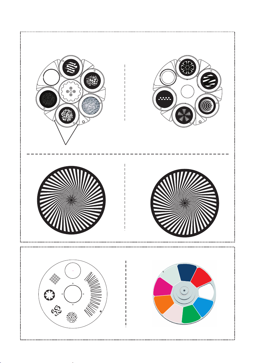
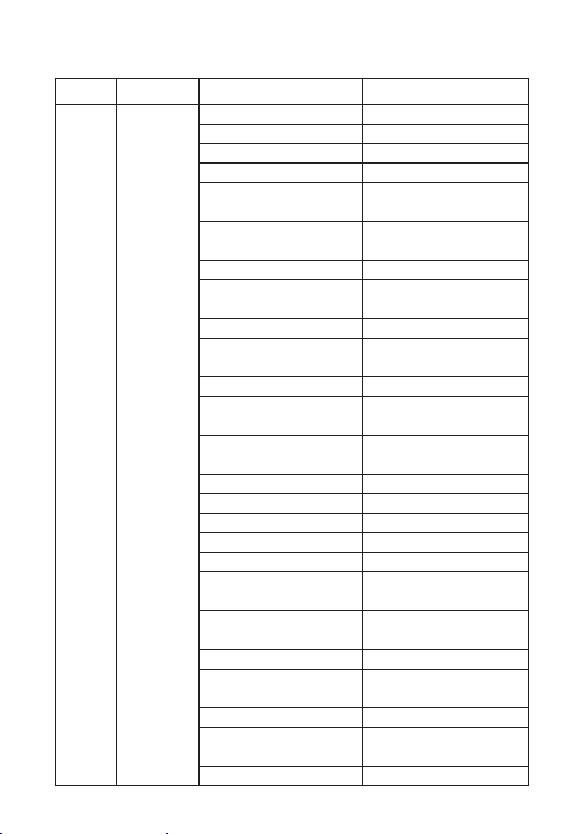
Color wheel
Rotation gobo wheel 1 Rotation gobo wheel 2
Gobo size:outside(φ36mm)/inside(φ27mm)
Fix wheel
Effect wheel
White
1-Blue
2-Green
3-1/2minus green
4-Orange
5-Magenta
6-CTB 8-Red
7-Congo
6
www.tourprolighting.com

ATTACHMENT AND BODY SIZE
Attachment contents- Fig. 1
Body Size---Fig 2
LAMP
1
SAFETY CORD
DMX CABLE
WARRANTY CARD
USER MANUAL
BRACKET
(fitted into projector)
7
www.tourprolighting.com

3
4
L
N
The projector can be installe
WARNING:with the exception of when the projector is positioned on the floor, the safety cable must be fitted.
This must be securely fixed to the support structure of the projector and then connected to the fixing point at
the centre of the base.
d on the floor resting on special rubber feet, on a truss or on the ceiling or wall.
Connecting to the mains suppply ---Fig 4
INSTALLATION AND CONNECTING
Installing the projector- Fig. 3
Mains
11
22
8
www.tourprolighting.com

DMX 512
5
SCREEN
1
3
2
DMX 512
3 PIN
SIGNAL
SIGNAL
SIGNAL
SCREEN
DMX512
5 PIN
1
2
3
4
5
SIGNAL
Connecting to the control signal line (DMX) - Fig. 5
◎ Please use the round 3 or 5-pin XLR plugs &sockets offered by menu facture to connect the first
projector's output to the second projector' input and connect the second projector's output to the
third projector's input. And in the same way for the rest,eventually connect the last projector's
output,all the projectors are together.
◎The projectors's control signal output or input by using the 3 or 5-pin XLR pug and socket.If need to
lengthen the communication cable,please make sure the both side of 3 or 5-pin plug is one to one .
(one to one,two to two,three to three).Otherwise,the communication cable will be interrupted.The
communicate cable is 2-cord screened cable 75Ω resistance with each core is at least a 0.5mm
diameter.(Caution:All the inside leading wire of 3 or 5-pin XLR plug couldn't touch each other or
plinth).
◎Recommend to use the DMX signal terminator for the installation to avoid the electronic noise dama
-ge the digital control signal.Simply speaking,DMX terminator is an XLR connector with a 120Ω 1/2W
resistor connected across pin 2 and 3.Which is then plugged into the output socket on the last projec
-tor in the chain.Refer to the connection.
LAMP REPLACEMENT
Adj ust lam p
Adj ust lam p
p
m
a
l
e
c
a
l
p
e
R
OUT
9
www.tourprolighting.com

6
Press the switch. The projector starts resetting the effects. At the same time, the following
information scrolls on the display :(please refer to the actual material)
CONTROL PANEL
WA RNI NG :HO T!
Max imum am bient t emper ature t = 38℃.
a
Alw ays dis conne ct from m ains be fore re placi ng the la mp.
Cau tion: Hot lam p. Allow t o cool fo r 30 minu tes
bef ore ope ning.
Ext erior s urfac e tempe ratur e under
ste ady sta te cond ition = 120 .
Pro longe d expos ure to
uns hield ed lamp c an
cau se eye an d skin bu rns.
℃
L
E
E
R
S
I
S
W
INTER NET
POWER S UPPLY A C100-240 V 50/ 60Hz
IN OUT
1=SCREEN
2=SIGNAL-
3=SIGNAL+
4=EMPTY
5=EMPTY
DMX PINS
LAMP: 1000W
POWER :1200W
Supply side
(please refer to the actual
material)
7
9
8
10
SETTING
MANUAL
INFO
TEST
PERSON
SERVICE
(“*”Display the current use
of information)
DMX Address
LAMP power:***
DMX range:*-**
***
1.LAMP ON TIME:***
2.LAMP POWER:***
3.RDM UID:****.********
4.PT SPEED MODE:***
5.CONTROL MODE:***
6.DMX ADDRESS:***
7.DMX RANGE:***
BASIC INFORMATIO
“*”Display the current use
of information
10
www.tourprolighting.com
SETTING
INFO
DMX Address
Channel mode
DMX input mode
Basic(30CH)
Extended(34CH)
001-512
MENU SETTING(V1.0)
ⅠMenu ⅡMenu Ⅲ Menu Ⅳ Menu Function
Wired input
Wireless input
Exit
Fixture Times
Fixture Temperatures
Fan Speed
Power On TIME ****H
Lamp On TIME ****H
ZOOM/FOCUS ***C
FEEECT ***C
CMYK ***C
PAN/TILT ***C
DISPLAY ***C
LAMP_TEM ***C
LAMP FAN L
FAN R ****RPM
****RPM
HEAD FAN L
FAN R ****RPM
****RPM
CMYK FAN ****RPM
RDM UID NULL...
11
www.tourprolighting.com
INFO
ⅠMenu ⅡMenu Ⅲ Menu Function
DMX Live
1.shutter
2.Dimmer
3.Dimmer fine
4.Cyan
5.Magenta
6.Yellow
7.CTO
8.Color Wheel
9.GOBO1 W sel
10.GOBO1 W I/R
11.GOBO1 W I/R f
12.GOBO2 W sel
13.GOBO2 W I/R
14.GOBO2 W I/R f
15.fixation Whee
16.fixation spee
17.Frost
18.Prism
19.Prism rota
20.Iris
21.Zoom
22.Zoom fine
23.Focus
24.Focus fine
25.Pan
26.Pan fine
27.Tilt
28.Tilt fine
29.Fixture contr
30.Effect
31.Effect rota1
32.Effect rota2
33.Calibration
34.FX
0-255
0-255
0-255
0-255
0-255
0-255
0-255
0-255
0-255
0-255
0-255
0-255
0-255
0-255
0-255
0-255
0-255
0-255
0-255
0-255
0-255
0-255
0-255
0-255
0-255
0-255
0-255
0-255
0-255
0-255
0-255
0-255
0-255
0-255
Exit
12
www.tourprolighting.com

INFO
ⅠMenu ⅡMenu Ⅲ Menu Ⅳ Menu Function
version info
LAMP ON/OFF
OFF
LAMP POWER
DMX LAMP OFF
PAN/TILT
PT SWAP
1000_6M_U_HARD:V*.**
SOFT:V*.**
1000_6M_D_HARD:V*.**
SOFT:V*.**
1000_XY_HARD:V*.**
SOFT:V*.**
1000_DPY_HARD:V*.**
SOFT:V*.**
1000_9M_HARD:V*.**
SOFT1:V*.**
SOFT2:V*.**
Exit
PERSON
ON
Default
----
OFF
ON Default
OFF
ON
Default
PAN INVERT
OFF
ON
TILT INVERT
OFF
ON
Exit
Default
Default
13
www.tourprolighting.com

ⅠMenu ⅡMenu Ⅲ Menu Ⅳ Menu Function
PAN/TILT SPEED
NORMAL
DMX RRESET
RESET
DISPLAY
DIMMER REST
CMYK REST
PERSON
FAST
Default
OFF
ON Default
EFFECTS RESET
SYSTEM RESET
Exit
SLOW
PAN/TILT RESET
DISPLAY LANGUAGE
DISPLAY SLEEP
ENGLISH(英文)
Light always
2 MINUTES
4 MINUTES
8 MINUTES
DISPLAY INTENSITY 10-100
DISPLAY ROTATION
AUTO
NORMAL
ROTATE 180
TFT Calibration
Exit
Default
Default
CHINESE(中文)
Exit
Default
14
www.tourprolighting.com

MANUAL
ⅠMenu Ⅱ Menu Function
1.Shutter
2.Dimmer
3.Dimmer fine
4.Cyan
5.Magenta
6.Yellow
7.CTO
8.Color Wheel
9.GOBO1 W sel
10.GOBO1 W I/R
11.GOBO1 W I/R F
12.GOBO2 W sel
13.GOBO2 W I/R
14.GOBO2 W I/R F
15.fixation W
16.fixation SP
17.Frost
18.Prism
19.Prism rota
20.Iris
21.Zoom
22.Zoom fine
23.Focus
24.Focus fine
25.Pan
26.Pan fine
27.Tilt
28.Tilt fine
29.Fixture Contr
30.Effect
31.Effect rota1
32.Effect rota2
0-255
0-255
0-255
0-255
0-255
0-255
0-255
0-255
0-255
0-255
0-255
0-255
0-255
0-255
0-255
0-255
0-255
0-255
0-255
0-255
0-255
0-255
0-255
0-255
0-255
0-255
0-255
0-255
0-255
0-255
0-255
0-255
Exit
15
www.tourprolighting.com

ⅠMenu ⅡMenu Ⅲ Menu Ⅳ Menu Function
TEST ALL
SERVICE
TEST
TEST PAN/TILT
TEST EFFECTS
Exit
Exit
ERROR LIST
ADJUST
Pan
Tilt
Effect
Focus
Zoom
Prism
Prism rota
Frost
Cyan
Magenta
Yellow
CTO
Shutter
Color Wheel
GOBO1 W I/R
Effect rota1
Iris
fixation Wheel
GOBO1 W sel
Effect rota2
GOBO2 W I/R
GOBO2 W sel
±5.00%
±5.00%
±5.00%
±5.00%
±5.00%
±5.00%
±5.00%
±5.00%
±5.00%
±5.00%
±5.00%
±5.00%
±5.00%
±5.00%
±5.00%
±5.00%
±5.00%
±5.00%
±5.00%
±5.00%
±5.00%
±5.00%
16
www.tourprolighting.com

ⅠMenu ⅡMenu Ⅲ Menu Ⅳ Menu Function
FAN CLEAN
SERVICE
UP DATA
FACTORY
Exit
OFF
ON
Default
17
www.tourprolighting.com

Basic
16-bit
Mode
Extended
Mode DMX Value Percent Function
0-19
20-49
50-200
201-210
211-255
0-65535
0-255
0-255
0-255
0-255
0
1-14
15
16-29
30
31-44
45
46-59
60
61-74
75
76-89
90
91-104
105
106-119
120
121-134
135-140
0-100
0-7
8-19
20-78
79-82
82-100
Shutter closed(Lamp switches to 800 watt mode after shutter is closed for 10 seconds)
Shutter open
Strobe,slow→ fast
Shutter open
Random strobe,slow → fast
Dimmer fade(MSB)
Closed →open
Dimmer fade,fine (LSB)
1
2
1
2
CHANNEL(V1.0)
Strobe/shutter
3
3
4
5
6
7
4
5
6
7
8
0-100
0-100
0-100
0-100
0
1-5
6
6-11
12
12-17
18
18-23
23
24-29
29
30-35
35
36-41
41
41-46
47
47-52
53-55
Open
Open → Slot1
Slot1
Slot1→Slot2
Slot2:
Slot2→Slot3
Slot3
Slot3→Slot4
Slot4
Slot4→Slot5
Slot5
Slot5→Slot6
Slot6
Slot6→Slot7
Slot7
Slot7→Slot8
Slot8
Slot8→Open
Open
Cyan
→White full cyan:0-100%
Magenta
→magentaWhite full :0-100%
Yellow
→yellowWhite full :0-100%
CTO
→Open warm
Color wheel
continuous scroll
18
www.tourprolighting.com
Table of contents
Other TourPro Lighting Lighting Equipment manuals


