Toyama TDMLG4004-T9C User manual


INDEX / INDICE / SUMÁRIO
SAFETY SYMBOLS / SIMBOLOS DE SEGURIDAD / SIMBOLOS DE SEGURANÇA........- 5 -
SPECIFICATIONS / ESPECIFICACIONES / ESPECIFICAÇÕES ......................................- 6 -
1. INTRODUCTION ...............................................................................................- 7 -
2. PREPARATION OF EQUIPMENT BEFORE USE...............................................- 7 -
3. CHECK LIST BEFORE USE ..............................................................................- 7 -
4. MANUAL WINCH MAST ....................................................................................- 8 -
5. SPECIFICATIONS .............................................................................................- 9 -
6. GENERATOR INSTRUCTION............................................................................- 9 -
7. ROUTINE MAINTENCE SCHEDULE ...............................................................- 13 -
8. TROUBLESHOOTING .....................................................................................- 15 -
9. INTRODUCCIÓN.............................................................................................- 16 -
10. PREPARACIÓN DEL EQUIPO ANTES DEL USO.........................................- 16 -
11. COMPRUEBE ANTES DE OPERAR............................................................- 16 -
12. MÁSTIL DEL CABESTANTES MANUAL.......................................................- 17 -
13. ESPECIFICACIONES ..................................................................................- 18 -
14. INSTRUCCIÓN DEL GENERADOR .............................................................- 19 -
15. CALENDARIO DE MANTENIMIENTO RUTINARIO......................................- 22 -
16. SOLUCIÓN DE PROBLEMAS......................................................................- 24 -
17. INTRODUÇÃO.............................................................................................- 25 -
18. PREPARAÇÃO DO EQUIPAMENTO ANTES DO USO.................................- 25 -
19. VERIFICAÇÕES ANTES DE OPERAR.........................................................- 25 -
20. MASTRO DO GUINCHO MANUAL ..............................................................- 26 -
21. ESPECIFICAÇÕES......................................................................................- 27 -
22. INSTRUÇÃO DO GERADOR.......................................................................- 27 -
23. CALENDÁRIO DE MANUTENÇÃO DE ROTINA ..........................................- 31 -
24. RESOLUÇÃO DE PROBLEMAS..................................................................- 33 -

PREFACE
Thank you for purchasing TOYAMA product.
This manual covers the operation and maintenance of a Toyama product. The information and
specifications included in this publication were in effect at the time of approval for printing. No
part of this publication may be reproduced without written permission. This manual should be
considered a permanent part of this product and should remain with it. The illustration may vary
according to the type.
Keep this owner’s manual handy, so you can refer to it at any time. This owner’s manual is
considered a permanent part of the product and should remain with the product if resold.
If a problem should arise, or if you have any questions about the product, consult you authorized
dealer.
PROLOGO
Gracias por comprar este Producto TOYAMA.
Este manual cubre la operación y el mantenimiento de este producto.La información y las
especificaciones incluidas en esta publicación son efectivas para la fecha de aprobación de
impresión.
Ninguna parte de esta publicación puede ser reproducida sin autorización.Este manual debe
ser considerado parte permanente del producto y debe mantenerse con el producto en caso
de ser revendido.Algunos detalles podrán cambiar dependiendo del modelo.
Conserve este manual a la mano para que usted se pueda referir a él em cualquier momento.
En caso de presentarse algún problema, o si usted tienen alguna pregunta sobre el producto,
contacte a su distribuidor TOYAMA.
PREFACIO
Obrigado por adquirir um Produto TOYAMA.
Este manual contém informações para operação e manutenção do seu produto. As
informações e especificações incluídas nesta publicação estavam em vigor no momento da
aprovação para impressão. Nenhuma parte desta publicação pode ser reproduzida sem
permissão por escrito. A ilustração pode variar de acordo com cada modelo de equipamento.
Mantenha este manual do proprietário sempre disponível, para que consiga consultá-lo a
qualquer momento. Este manual é considerado uma parte permanente do seu produto e deve
acompanhar o equipamento ao ser revendido.
Ao surgir um problema, ou se você tem dúvidas sobre o seu produto, consulte o seu
revendedor autorizado TOYAMA.

SAFETY SYMBOLS / SIMBOLOS DE SEGURIDAD / SIMBOLOS DE SEGURANÇA
The following symbols are intended to remind you of the safety precautions to be followed /
Los siguientes símbolos tienen el objetivo de recordarle las precauciones de seguridad que
deben respetarse
Os símbolos seguintes tem o objetivo de lembra-lo sobre as precauções de segurança que
devem ser respeitadas.

SPECIFICATIONS / ESPECIFICACIONES / ESPECIFICAÇÕES
Modelo / Model
TDMLG4004-T9C
Tipo / Tipo / Type :
Torre de Iluminação Toyama, Com Motor Diesel, 4 Tempos, 3
Cilindros, Refrigerado a Agua
Torre de Iluminación Toyama, Motor Diesel 4 Tiempos, 3 Cilindros,
Refrigerado per Agua
Toyama Diesel Engine Lightning Tower, 4 Strokes, 3 Cylinders,
Water Cooled
Cilindrada / Cilindrada / Displacement
[cm³] :
1532
Rotação / Rotación / speed [rpm]:
1800
Sistema de partida / Sistema de arranque /
Starting system:
Elétrica / Electrico / Electric
Tank Capacity | Capacidad del Tanque |
Capacidade do Tanque
110 l
Engine Oil Capacity | Capacidad de Aceite
del Motor | Capacidade do Óleo do Motor
4.1 l
Recommended Oil | Aceite Recomendado |
Óleo Recomendado
15W40
Radiator Water Capacity | Capacidad de
agua del radiador | Capacidade de Agua no
Radiador
6 l
Fase / Fase / Phase :
Monofásico / Monofásico / Single Phase
Frequência / Frecuencia /Frequency:
60 Hz
Output Voltage | Voltaje de Salida | Tensão
de Saida
220 V
Regulador de Tensão / Regulador de
Voltaje / Voltage regulator
Capacitor / Capacitor / Brushless
Altura do mastro / Altura del mástil / Mast
Height [m]
9
Potência nominal / Potencia Nominal /
Rated POWER [VA] :
8500
Rodas / Ruedas / Wheels:
14”
Lampada / Light / Lampara
4 x 1000 W
Dimensões (CxLxA)/ Dimensiones /
Dimensions (lxwxh) [mm] :
1850 x 1500 x 4600
Peso líquido/ Peso Neto / Net weight [kg] :
958
Peso bruto / Peso Bruto/Gross weight[kg]:
1000

1. INTRODUCTION
This manual provides the information for the safe operation of lightning tower.
The standard tower configuration is operated with a manual crank winch and an electric winch
used to erect ,extend, and lower the light.
Specification and instruction operating are contained in this manual to familiarize the contents
with correct and safe procedures necessary to operate the equipment.
Take time to read this book thoroughly . If you are uncertain about any of the information
presented in the manual, contract our technical or your dealer for clarification before
operation.
NOTE: Failure to understand comply with safety related informational instructions may result
in injury to operator or others people. Any reference in this manual to LEFT or RIGHT shall be
determined by looking at the trailer from the rear.
2. PREPARATION OF EQUIPMENT BEFORE USE
The lighting tower requires service as well as proper operation in order to provide the good
performance. Never operate a machine into service with known defects or missing
INSTRUCTION decals. Reading the proper operation and safety procedures carefully as
described in the operator’s manual.
Always provide the manual with the equipment for proper and safe operation.
3. CHECK LIST BEFORE USE
Visually inspect the equipment to ensure that all instructions and decals are in place and
legible.
Inspect the tower latch and knob assembly, which locks the tower in the vertical position for
proper position.
Check the hitch assembly and safety tow chains.
Check the outriggers and jacks to make sure they operate properly.
Inspect the light assemblies for damage and test for proper operation.
Inspect the tires to ensure good condition and proper inflation.
Check oil, fuel, coolant levels, and hydraulic fluid level.
Check to make sure the operator’s manual is with the equipment.
Inspect the machine physically for damage and repair if necessary.
NOTE: See appropriate section of manual for scheduled maintenance interval.
WARNING
NEVER ALLOW ANYONE TO OPERATE EQUIPMENT WITHOT PROPER TRAINING!
ALWAYS READ THE INSTRUCTIONS FIRST.

4. MANUAL WINCH MAST
The lighting tower assembly consists of a three-section telescoping mast which can be raised
and extended by operating the manual winch. This winch, mounted with the handle extending
at the back of the trailer flame, raises and lowers the mast from the horizontal towing position,
the vertical position, and the back. And the manual extends the telescopic sections.
Lock pin at lower right position and pull upper left pin out to raise or lower the three section
mast as necessary.
WARNING
Always check for overhead obstructions before raising and lowering mast. Avoid all overhead
electrical wires.
To prevent instability and help ensure safe operation, always provide proper ground support
before raising mast.
Before raising mast, visually inspect equipment for damage or wear .
NOTE: The latch locks the mast in the vertical position and disengages the sections allowing
the tower assembly to be rotated to position the lights.
TO LIFT THE MAST AND LIGHTS
Open side outrigger, rear hydraulic jack and front hydraulic jack to stabilize and level the
trailer.
NOTE: Hydraulics jacks should be placed only on firm ground.
WARNING
When open rear jack, watch to ensure you are clear of the mast before you stand up.
Inspect equipment for damage before operating. Allow adequate clearance around trailer for
tower and insure that no person are standing in front of or behind the machine when lowering.
TO LOWER MAST AND LIGHTS
1. Turn off lights.
2. Operate hand crank winch on tower counter-clockwise to lower the lights to the lowers
vertical position.
3. Operate hand crank winch on side of trailer clockwise to take up any cable slack.
4. Operate the hand crank on the side of the trailer counterclockwise to fold the mast down into
the towing position.
5. Raise jacks and rear stand, retract outriggers and secure for towing.
NOTE: Sufficient load must be applied to the cable to overcome internal resistance and operate
the brake properly. Insufficient load will not turn the reel thus continual turning without sufficient
load will remove the winch handle from the shaft. After working, fold three section mast and
lock the pin to put mast horizontal level.

5. SPECIFICATIONS
TRAILER
The complete generator is housed in lockable enclosure with the frame fabricated from heavy
gauge steel mooned on a two-wheel, leaf spring axle.
When the mast is in the operating position it is located in the middle of a three-point outrigger
system for optimum balance and stability. This system was engineered to allow the high tower
to remain operational in sustained winds of 70 km/hr with the mast extended full height and
the outrigger in position.
MAST
The mast consist of a three section steel tube that extends 9m.
The mast is extended with two manual winches. The mast includes self-lubricating nylon
guide pads and a 360-degree Rota table light bar.
STABILIZERS
The three-points outrigger design consists of two retractable side outriggers and a hydraulic
jack.
FLOOD LIGHT
The flood light assembly consists of four 1000-watt lamp or four 400-watt LED lamp fixtures
sealed for all weather use.
Laboratory rated life is 12,000 hours
Warm up time:2-4 minutes
Restart time:10-15
TOWING INSTRUCTION
Before towing the trailer should be inspected visually to insure that the following operations
have been completed:
1. Hitch is securely attached to the towing vehicle(safety chain securely attached)
2. All outriggers and jacks are retracted and secured.
3. Rear tower support pin is in the locked position.
4. Light fixtures are positioned for transport.
5. Doors are closed and secure.
6. Check for adequate tire pressure.
7. Trail lights are connected and operational.
6. GENERATOR INSTRUCTION
PREPARATION BEFORE OPERATION
a. Add anti-freezing liquid to ready diesel generator.
b. Verify and add oil to generator, if necessary. Too much or too less are bad for engines.
c. Connect the diesel line, exhaust air in oil tube to make it easy to start diesel generator. It’s
better to use 0# 0r -10# diesel.
d. Choose wire with right capacity based on power of generator to be connected to output end
of main circuit breaker. Connect phase line and null line with right position. Also connect
the connection line based on drawing.
e. Make sure all ground connection good such as controller, generator body and etc.

f. Connect battery line, be careful with positive and negative charges. Positive battery line
first, then negative battery line.
g. Tighten all bolts on each part of generator.
h. Before starting, main circuit breaker on ‘BREAK’ position.
i. After all above check lists, start the generator to have a try, before loading start, still need
check if phase line same as local electric phase, if everything OK, loading working is
accepted.
PANEL KEYS
Key
Definition
Description
Manual/Decrease
Pressing this button will start the generator manually and
place it into its manual mode; in settings menu moves
cursor down an decreases the set value.
Auto/Increase
Pressing this button will place the module into its auto
mode; in settings menu moves cursor up and increases
the set value
Stop
Pressing this button in any situation will shut down the
generator and place it into its standby mode; in case of
alarm, pressing this button will clear alarms
Turn
Page/Confirm
Using this button you can scroll pages of the LCD monitor;
in settings menu press to move cursor and confirm
Alarm Indicator
This indicator will flash when an alarm occurs

LCD ICONS
Icon
Definition
Icon
Definition
High Temp. Alarm
Auto Mode
Low Oil Pressure
Stop Mode
Over Speed Alarm
Manual Mode
Under Speed Alarm
Gens Volts Indication
Emergency Stop
Battery Volts
Indication
Over Voltage
Speed Unit (Per min)
Under Voltage
Oil Pressure unit
Fail to Start
Voltage Unit
Fail to Stop
Fuel Level Unit
Voltage Abnormal
Temperature Unit
Auxiliary Alarm
Frequency Unit
Normal Run
Hours Count
Fuel Level Low
Load Current

OPERATION
The module has three working modes:
Manual Mode( ) ,Auto Model( ) and Stop Mode( ).
MANUAL START
After pressing Manual Start button and holding it for at least one second, the indicator next to
the button will be illuminated, Preheating output will be activated firstly and preheat delay begins.
One second before it is finished, fuel output will be activated for one second and after that
preheat output will be deactivated; starter is energized to output and engine cranks. When
generator frequency reaches the pre-set value, the starter motor will be deactivated and
generator will start. Then, safety delay will start, after it is finished, idle delay will start and when
it is finished idle relay will be closed and the generator will start working at normal speed.
AUTO MODE
After pressing and holding button for at least one second, the indicator next to the button will
be illuminated and the module will be placed into its automatic mode. If remote start signal is
active(remote start input port is connected to B-), after start delay the genset will start.
Preheating output will be activated firstly and preheat delay begins. One second before it is
finished, fuel output will be activated for one second and after that preheat output will be
deactivated; then starter is energized to output ( engine will try to start according to the pre-set
number of times; if one of the attempts is successful, the start process will be completed,
otherwise fail to start alarm will be initiated: fail to start indicator on the panel will be illuminated
and common alarm indicator will flash). After start delay and idle delay, idle replay will be
deactivated and the generator will start working at normal speed.
NOTE: During crank rest time, fuel output is deactivated; three seconds after the beginning of
the delay, preheat and ETS outputs will be activated; after the end of the delay, ETS output will
be deactivated and fuel replay output; preheat output will be deactivated before the beginning
of crank.
When remote start signal is deactivated, after stop delay, the generator enters idle state and
the idle relay is deactivated. After idle delay, fuel replay deactivates, ETS relay output activates,
and the genset automatically stops. After complete stop, EYS relay deactivates.
STOP MODE
After pressing and holding for at least one second during normal operation of the genset ( in
manual or auto modes), the light indicator near the button will be illuminated and idle operation
will begin. When idle relay deactivates and after idle delay, fuel relay is deactivated and ETS
output is energized. When complete stop of the generator, ETS is deactivated.
In case of fault alarm, pressing and holding the button for one second will clear alarms. Holding
it for more than one second will illuminate all indicators on the panel (light test function).
Pressing this button for more than one second in stop mode will lead to activation of ETS output
and illumination of all the indicators on the panel(light test function). Releasing the button will
immediately deactivate ETS output and light test function.
When in stop mode, the module will only react to emergency stop signal.
NOTE: Configurable output ports can be set as one of the following functions: ‘ETS output’ ‘Idle
output’ or ‘preheat output’ via PC. There for, all three functions cannot be active at the same
time; the above-mentioned is only to describe the logical course of action of the controller in

case all three functions are active.
Total current of mobile light tower is twice as what the module shows which is voltage and
current of A phase.
7. ROUTINE MAINTENCE SCHEDULE
INSPECTION AND LUBRICATION SCHEDULE:
Service intervals shown below have been established for operation under normal conditions.
Where equipment is operated under serve conditions( very dusty, extreme heat or cold, etc.)
affected items should be serviced more frequently.
LUBRIFICATION GREASE SPECIFICATIONS:
N.G.L.I. consistency n°2, high temperature anti-friction bearing lubrication greases.

INTERVAL
ITEM
PROCEDURE
Daily or 10
hours
Fuel level
Check level and fill as necessary
Coolant
Check level and complete as necessary
Steel wire
Check tightness
Alternator belt
Check tension
Engine oil
Check level and condition
Leaks or damage
Visual check
In the first 20
hours
Engine Oil
Replace
Air filter
Replace oil, clean the element
Bolts and nuts
Check and tighten, if necessary
100 hours or 3
months
All 10 hours items
As above
Air cleaner
Check and Clean
Battery
Check level of electrolyte
Idling
Check and adjust
Engine oil
Replace
200 hours or 6
months
All 100 hours items
As above
Air filter
Clean and replace the element
Fuel filter
Replace
400 horas or
12 months
Injectors nozzles
Check and replace, if necessary
600 horas or
18 months
All 200 hours items
As above
Fan belt
Check conditions
Alternator
Replace the belt
Electric system
Check
Radiator
Clean out fins with water or air
1000 Hours or
24 months
All 600 hours items
As above
Engine valves
Adjust clearance
Cable pulley at bottom of the
front mast support
Inspect for wear, clean and grease
Cable pulleys on mast
Remove, clean, and grease
Axle wheel bearings
Clean and repack
Fuel system
Clean sediment from tank

8. TROUBLESHOOTING
WARNING
Do not try to test and repair the generator and ballast electric system unless you are the a
qualified technical electrician.
Turn off the generator when the light is not shinning. And test the shined light’s lead. Do not
wear any jewelry when operate it! If the following procedure still cannot solve your problem,
please ask the qualified technical electrician to test the circuit.
Problem
Possible cause
One
or
more
lights
do
not
lights
up
1.Circuit breakers in the outlet bis are not turned on or have tripped
2.You must have five minutes between the time the lights are shut off
and the time they are restarted
3.The lamp or lamps are burned out or broken
4.One or more of lamps are not screwed in securely
5.Plug and socket at light bar not securely pushed together and locked
6.The temperature of the ballast is below 20degreesF, the efficiency
of the capacitors in the ballast is not enough to ignite the lamps, For
operations where the temperature of the ballast falls below 20degrees
F, some means of warming the ballast must be used.
7.Low electrical system voltage
8.A loose connection in the back off the lamp socket in the lamp holder
9.A circuit breaker or breakers are defectives
10.A loose connection on the terminal board
11.Engine and generator are not running up to the speed 1500 RPM
(50HZ) OR 800 RPM(60HZ)
12.A wrong style replacement lamp(requiring a different ballast)has
been installed
13.Too much power is being drawn from the auxiliary outlets
14.Capacitor or transformer has failed
15.Corrosion has occurred on the lamp bases

9. INTRODUCCIÓN
Este manual proporciona las informaciónes para el uso seguro de la torre de iluminación.
Las instrucciones y especificaciónes operacionales están contenidas en este manual para
familiarizar el contenido con los procedimientos correctos y seguros nrequeridos para operar
el equipo.
Tome un tiempo para leer este manual a fondo. Si no estás seguro sobre alguna de las
informaciónes presentada en esta manual, contacte con su distribuidir o té cnico autorizado
para obtener aclaraciones antes de poner la maquina en marcha.
NOTA: No comprender y no seguir las intrucciones relacionadas con la seguridad podria
provocar lesiones al operador y a otras personas.
Cualquier referencia en este manual a la IZQUIERDA o DERECHA debe debe determinarse
mirando el remolque desde la parte trasera.
10. PREPARACIÓN DEL EQUIPO ANTES DEL USO
La torre de iluminación requiere un servicio y operación adecuados para proporcionar un buen
rendimiento. Nunca opere una máquina en servicio con defecto o calcomanías que faltan en
las INSTRUCCIÓNES. Lea los procedimientos de operación y seguridad adecuados
cuidadosamente como se describe en el manual del operador.
Siempre proporcione el manual con el equipo para una operación adecuada y segura.
11. COMPRUEBE ANTES DE OPERAR
Inspeccione visualmente el equipo para asegurarse de que todas las instrucciones y
calcomanías estén en su lugar y sean legibles.
Inspeccione la traba de la torre y el conjunto del botón, que bloquea la torre en la posición
vertical para la posición correcta.
Compruebe el conjunto de acoplamiento de las corrientes del romolque de seguridad.
Comprube los es estabilizadores y los enchufes para asegurar que funcionen correctamente.
Ispeccione los conjuntos de las luces en busca de daños y pruebe el funcionamiento.
Inspeccione los neumaticos para garantizar un buen estado y una inflación apropiada.
Compruebe el nivel del aceite, del combustible, del líquido de enfriamiento y el del líquido
hidráulico.
Compruebe si el manal del operador esté con el equipo.
Inspeccione la máquina en busca de daños físicos y repare si es necesario.
NOTA: Consulte la sección correspondiente del manual para obtener el intervalo de
mantenimiento programado.

ADVERTENCIA
NOTA: NUNCA DEJES A NADIE OPERAR EL EQUIPO SIN FORMACIÓN ADECUADA!
SIMPRE LEA LAS INSTRUCCIONES.
12. MÁSTIL DEL CABESTANTES MANUAL
El conjunto de la torre de iluminación consiste en un mástil telescópico de tres secciones que
se puede elevar y extender al operar el cabrestante manual. Este cabrestante, montado con la
manija que se extiende hacia la parte trasera del remolque, sube y baja el mástil desde la
posición del remolque horizontal, vertical y tesera. Y el manual extiende las secciones
teelscópicas.
Bloquee el pasador en la posición inferior derecha y tire el pasador superior izquierdo para
subir o bajar el mastil de tres secciones, según sea necesario
ADVERTENCIA
Siempre revise si hay obstrucciones aereas antes de subir y bajar el mastil. Evite todos lso
cables eléctricos aéreos.
Para evitar la inestabilidad y ayudar a garantizar un funcionamiento seguro, siempre
proporcione un soporte de suelo adecuado antes de levantar el mástil.
Antes de levantar el mastil, inspeccione visualmente el equipo en busca de daños o desgaste.
NOTA: El pestillo bloquea el mástil en la posición vertical y desengancha las secciones, lo que
permite girar el conjunto de la torre para ajustar las luces.
O trinco trava o mastro na posição vertical e desengata as seções, permitindo que o conjunto
da torre seja girado para posicionar as luzes.
PARA SUBIR EL MÁSTIL
Con el estabilizador lateral abierto, gato hidráulico trasero y gato hidráulico delantero para
estabilizar y nivelar la torre .
NOTA: Gato hidráulico solo debem colocarse en terreno firme.
ADVERTENCIA
Al abrir la salida trasera. tenga cuidado de no tocar el mástil antes de levantarse.
Inspeccione el equipo por daños antes de operar. Deje espacio libre adecuado altedor del
remolque para la torre y asegpurese de que nadie esté delante o detrás de la máquina cuando
baje.
PARA BAJAR EL MÁSTIL Y LAS LUCES
1. Apaga las luces.
2. Opere la manivela del cabrestante en la torre en sentido antihorario para bajar las luces a la
posición vertical más baja.
3. Opere la manivela del cabrestante en el lado del remolque en sentido horario para quitar
cualquier flojidez del cable
4. Accione la manivela en el costado del remolque en sentido antihorario para doblar el mástil

para la posicion de remolque.
NOTA: Se debe aplicar suficiente carga al cable para superar la resistencia interna y operar el
frenar correctamente. La carga insuficiente no hará girar el carrete, por lo tanto, el giro continuo
sin carga suficiente eliminará la manivela del cabrestante del eje.
5. Levante los gatos y el soporte trasero, recoja los estabilizadores y asegúrelos para
remolcarlos.
NOTA: Después del trabajo, doble el mástil de tres secciones y bloquee el pasador para poner
el mástil en la posición horizontal.
13. ESPECIFICACIONES
REMOLQUE
El generador completo está alojado en un compartimento con cerradura con la estructura
hecha de acero de gran calibre recubierto con un eje de resorte de dos ruedas.
Cuando el mástil está en la posición de operación, se encuentra en el medio de un Estabilizador
de tres puntos para un mejor equilibrio y estabilidad. Este sistema fue diseñado para permitir
que la torre alta permanezca operativa con vientos sostenidos de hasta 70 km / h con mástil
extendido a toda altura y estabilizador en posición.
MÁSTIL
El mástil consta de un tubo de acero de tres secciones que se extiende por 9 metros.
El mástil se extiende con dos cabrestantes manuales. El mástil incluye guías de nylon
autolubricantes y una barra de luces giratoria de 360 grados.
ESTABILIZADORES
El diseño del estabilizador de tres puntos consta de dos estabilizadores laterales retráctiles y
un gato hidráulico.
MONTAJE DE LAS LUCES SUMERGIBLES
El conjunto de luces consta de cuatro lámparas de 1000 vatios o cuatro LED sellado de 400
vatios para usar en cualquier clima.
La vida nominal es de 12.000 horas.
Tiempo de calentamiento: 2-4 minutos.
Tiempo de reinicio: 10-15.
INSTRUCCIONES DE REMOLQUE
Antes de remolcar, el remolque debe ser inspeccionado visualmente para asegurarse de que
lo siguiente pasos se hallan completado:
1. El acoplador está firmemente sujeto al vehículo de tracción(cadena de seguridad bien sujeta)
2. Todos los estabilizadores y gatos están retraídos y bloqueados.
3. El pasador del soporte de la torre trasera está en la posición bloqueada.
4. Las luminarias están posicionadas para el transporte.
5. Las puertas están cerradas y seguras.
6. Verifique la presión adecuada de los neumáticos.
7. Luces de tráfico están conectados y operativos.

14. INSTRUCCIÓN DEL GENERADOR
PREPARACIÓN ANTES DE LA OPERACIÓN
a. Agregue liquido refrigerante al motor del generador a diesel.
b. Verifique y agregue si necesario aceite al motor del generador.
c. Elimine el aire del conducto del motor si es necesario.
d. Elija el cable de capacidad correcta, en función de la potencia del generador a ser conectado
al extremo de salida del disyuntor principal. Conecte la línea de fase y la línea nula en la
posición correcta. También conecte la línea de conexión según el dibujo.
e. Verifique de que todas las conexiones a tierra sean correctas, como el controlador, cuerpo
del generador y etc.
f. Conecte los cables de la batería, tenga cuidado con las cargas positivas y negativas. Cable
positivo de la bateria primero, luego el cable negativo de la batería.
g. Apriete todos los tornillos en cada parte del generador.
h. Antes de comenzar, el disyuntor principal debe estar en la posición 'BREAK'.
i. Después de comprobar todos los pasos anteriores, encienda el generador para poner a
prueba, antes de iniciar el proceso de carga, todavía es necesario verificar que la línea de fase
sea igual a la fase eléctrica local y si todo está funcionando correctamente
TECLAS DEL PANEL
Llave
Definición
Descripción
Arranque /
Disminución
Presione este botón para iniciar el generador manualmente y
ponerlo en modo manual; en el menú de configuración mueve
el cursor hacia abajo y disminuye el valor establecido.
Automático /
Aumentar
Presione este botón para iniciar el modo automático: en el
menú de configuración mueve el cursor a arriba y aumentar el
valor establecido
Parar
Al presionar este botón en cualquier situación hará con que el
generador se apague y lo pondra en modo de espera; en
caso de alarma, al presionar este botón se apagaran las
alarmas.
Pasar página /
Confirmar
Use este botón para desplazarse por las páginas de la pantalha
LCD; en menú de configuración, presione para mover el cursor
y confirmar.
Indicador de alarma
Este indicador parpadea cuando se enciende una alarma.

ICONOS LCD
Icono
Definición
Icono
Definición
Alta temperatura
Modo automático
Baja preción del
aceite
Modo de parad
Alarma de exceso de
velocidad
Modo manual
Alarma de baja
velocidad
Indicador de voltaje
Parada de
emergencia
Indicador de voltage
da la batería
Sobretensión
Unidad de velocidad
Baja tensión
Unidad de preción del
aceite
Error al iniciar
Unidad del voltaje
Error al parar
Unidad del nivel de
combustible
Tensión anormal
Unidad de
temperatura
Alarma auxiliar
Unidad de frecuencia
Operación normal
Medidor de horas
Nivel de combustible
bajo
Corriente de carga
Table of contents
Languages:
Other Toyama Portable Generator manuals
Toyama
Toyama TG950TH User manual
Toyama
Toyama TEPU1.5S-220 User manual
Toyama
Toyama TG15000CXE User manual
Toyama
Toyama TDG8000BXE User manual

Toyama
Toyama TG4000I-120V User manual
Toyama
Toyama ATS User manual
Toyama
Toyama TG10000CXE User manual

Toyama
Toyama TG3100 User manual
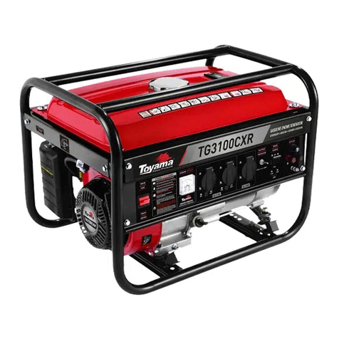
Toyama
Toyama TG3100CXR User manual
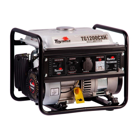
Toyama
Toyama TG1200 User manual
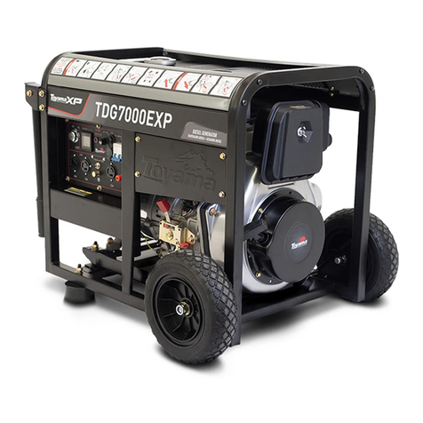
Toyama
Toyama TDG7000EXP User manual
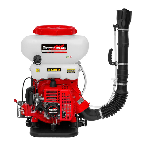
Toyama
Toyama TMD42BU User manual

Toyama
Toyama TG12000CXNE User manual

Toyama
Toyama XP LINE User manual
Toyama
Toyama TDWG12000CXE-N User manual

Toyama
Toyama TG2800 User manual
Toyama
Toyama TWGD220EXP User manual
Toyama
Toyama TDG2500XP User manual
Toyama
Toyama TDG7000SEXP User manual
