manuals.online logo
Brands
  1. Home
  2. •
  3. Brands
  4. •
  5. Tektronix
  6. •
  7. Portable Generator
  8. •
  9. Tektronix FG501 User manual

Tektronix FG501 User manual

Tektronix
COMMITTED
TO
EXCELLENCE
FUNCTION
GENERATOR
FG
501
INSTRUCTION
MANUAL
Tektronix
COMMITTED
TO
EXCELLENCE
FUNCTION
GENERATOR
FG
501
INSTRUCTION
MANUAL
Tektronix,
Inc.
P.O.
Box
500
Beaverton,
Oregon
97077
Serial
Number
______________________
070
1431-01
First
rinting
August
I972
W RR NTY
This
Tektronix
product
is
warranted
against
defective
materials
and
workmanship,
under
normal
use,
for
a
period
of
one
year
from
date
of
initial
shipment.
Tektronix
will
repair
or
replace,
at
its
option,
those
products
determined
to
be
defective
within
the
warranty
period
and
returned,
freight
prepaid,
to
a
Tektronix
Service
Center.
There
is
no
implied
warranty
for
fitness
of
purpose.
Please
direct
all
requests
for
service
or
replacement
parts
to
the
nearest
Tektronix
Service
Center
or
Field
Office;
include
the
type
or
part
number
of
the
product
and
its
serial
number.
Copyright
©
1972,
1978
by
Tektronix,
Inc.
ll
rights
reserved.
Contents
of
this
publication
may
not
be
reproduced
in
any
form
without
the
permission
of
Tektronix,
Inc.
Products
of
Tektronix,
Inc.
and
its
subsidiaries
are
covered
by
U.S.
and
foreign
patents
and/or
pending
patents.
TEKTRONIX,
TEK,
SCOPE-MOBILE,
TELEQUIPMENT,
and
are
registered
trademarks
of
Tektronix,
Inc.
Printed
in
U.S. .
Specification
and
price
change
privileges
are
reserved.
FG
501
WARNING
T BLE
OF
CONTENTS
Page
SECTION
1
OPERATING
INSTRUCTIONS
1-1
SECTION
2
SPECIFICATION
AND
PERFORMANCE
CHECK
2-1
THE
FOLLOWING
SERVICING
INSTRUCTIONS
ARE
FOR
USE
BY
QUALIFIED
PER

SONNEL
ONLY.
TO
AVOID
PERSONAL
INJURY,
DO
NOT
PERFORM
ANY
SERVICING
OTHER
THAN
THAT
CONTAINED
IN
OPERATING
INSTRUCTIONS
UNLESS
YOU
ARE
QUALIFIED
TO
DO
SO.
SECTION
3
ADJUSTMENT
3-1
SECTION
4
MAINTENANCE
AND
INTERFACING
INFORMATION
4-1
SECTION
5
CIRCUIT
DESCRIPTION
5-1
SECTION
6
OPTIONS
6-1
SECTION
7
REPLACEABLE
ELECTRICAL
PARTS
7-1
SECTION
8
DIAGRAM
AND
CIRCUIT
BOARD
ILLUSTRATION
8-1
SECTION
9
REPLACEABLE
MECHANICAL
PARTS
AND
EXPLODED
VIEW
9-1
CHANGE
INFORMATION
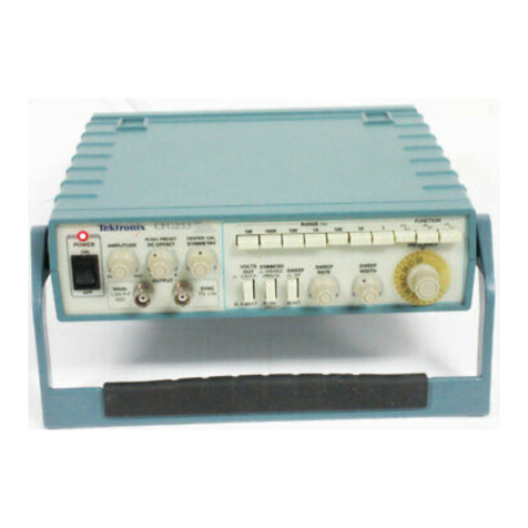
Fig.
1-1.
FG
501
Function
Generator
FG
501
REV.
B
JUL
1978
Section
1
—
FG
501
OPER TING
INSTRUCTIONS
INTRODUCTION
The
FG
501
Function
Generator
is
designed
to
o erate
in
a
TM
500-Series
ower
module.
Low
distortion
sine,
square,
triangle,
ulse,
and
ram
waveforms
from
0.001
Hz
to
1
MHz
as
well
as
a
+2.5
volt
square-wave
trigger
are
available
at
the
front
anel.
Variable
DC
offset
of
±7.5
volts
is
also
rovided.
A
"hold"
feature
allows
the
generator
out ut
to
be
abru tly
halted
at
its
instantaneous
voltage
level
and
held
there
until
manually
switched
on
again.
A
voltage-controlled
frequency
(VCF)
in ut
is
rovided
to
control
the
out ut
frequency
from
an
external
voltage
source.
The
out ut
frequency
can
be
swe t
above
or
below
the
selected
frequency
to
a
maximum
of
1000:1
de ending
on
the
olarity
and
am litude
of
the
VCF
in ut
and
the
selected
out ut
frequency.
Also
included
is
an
external
gate
in ut
that
allows
the
generator
to
be
turned
on
for
the
duration
of
an
externally
a lied
gating
signal.
This
mode
rovides
either
a
single
cycle
out ut
or
a
train
(burst)
of
reselected
waveforms
de ending
on
the
gating
signal
width
and
the
generator
frequency
setting.
The
hase
(start
level)
of
the
waveform
burst
can
be
varied
±90°
by
a
front- anel
control.
The
variety
of
swe t
and
modulated
signals
available
from
the
FG
501
make
it
es ecially
useful
for
such
a lications
as
testing
servo-system
or
am lifier
res onse,
distortion,
and
stability;
FM
generation
and
frequency
multi lication;
or
sim ly
used
as
a
variable
beat-frequency
oscillator,
re etition-rate,
or
tone-burst
generator.
The
square-wave
trigger
out ut
can
be
used
as
a
source
for
transistor-transistor
logic
(TTL)
or
to
syn

chronize
an
external
device
such
as
an
oscillosco e
or
counter.
The
FG
501
is
calibrated
and
ready
for
use
when
received.
It
is
designed
to
o erate
in
any
com artment
of
a
TM
500-Series
ower
module
only.
Refer
to
the
ower
module
Instruction
Manual
for
line
voltage
requirements
and
ower
module
o eration.
Installation
and
Removal
Turn
th
pow r
modul
off
b for
ins rting
th
plug

in;
oth rwis ,
damag
may
occur
to
th
plug-in
circuitry.
B caus
of
th
high
curr nt
drawn
by
th
FG
501,
it
is
also
r comm nd d
that
th
pow r
modul
b
turn d
off
b for
r moving
th
FG
501.
R f r
to
Fig.
1-2.
Ch ck
to
s
that
th
plastic
barri rs
on
th
int rconn cting
jack
of
th
s l ct d
pow r
modul
compartm nt
match
th
cut-outs
in
th
FG
501
circuit
board
dg
conn ctor.
Align
the
FG
501
chassis
with
the
u er
and
lower
guides
of
the
selected
com artment.
Push
the
module
in
and
ress
firmly
to
seat
the
circuit
board
in
the
inter

connecting
jack.
Pull
the
Power
switch
on
the
front
anel
of
the
ower
module
to
a ly
ower
to
the
FG
501.
Observe
that
the
POWER
indicator
light
on
the
FG
501
comes
on.
Remove
the
FG
501
from
the
ower
module
by
ulling
the
release
latch
at
the
bottom
of
the
front
anel
and
sliding
the
unit
straight
out
of
the
ower
module.
Fig.
1-2.
Plug-in
installation
and
removal.
1-1
REV.
C
JUL
1978
Operating
Instructions
—
FG
501
OPER TING
CONSIDER TIONS
NOTE
B for
using
th
FG
501
for
th
first
tim ,
r ad
th
Op rating
Consid rations
in
this
s ction
and
th
d scription
of
th
front-pan l
controls,
conn ctors,
and
indicators
in
Fig.
1-3.
Output
Connections
The
out ut
of
the
FG
501
is
designed
to
o erate
as
a
voltage
source
in
series
with
50

and
working
into
a
50

load.
At
the
higher
frequencies,
an
unterminated
or
im ro erly
terminated
out ut
will
cause
excessive
aberrations
on
the
out ut
waveform
(see
Im edance
Matching
discussion).
Loads
less
than
50

will
reduce
the
waveform
am litude.
Excessive
distortion
or
aberrations
due
to
im ro er
termination
is
less
likely
to
occur
at
the
lower
frequencies
(es ecially
with
sine
and
triangle
waveforms).
However,
to
ensure
that
waveform
urity
is
reserved,
observe
the
following
recautions:
1.
Use
quality
50
O
coaxial
cables
and
connectors.
2.
Make
all
connections
tight
and
as
short
as
ossible.
3.
Use
quality
attenuators,
if
necessary,
to
reduce
waveform
am litude
to
sensitive
circuits.
4.
Use
terminators
or
im edance-matching
devices
to
avoid
reflections
when
using
long
cables,
i.e.,
six
feet
or
more.
5.
Ensure
that
attenuators,
terminations,
etc.
have
adequate
ower-handling
ca abilities
for
the
out ut
waveform
(a roximately
0.5
W
into
a
50

load).
Power
out ut
is
determined
by
the
selected
waveform,
its
am litude,
and
the
amount
of
offset
voltage
selected.
The
hysical
and
electrical
characteristics
of
the
ulse

transmitting
cable
determine
the
characteristic
im

edance,
velocity
of
ro agation,
and
amount
of
signal
loss.
Signal
loss,
due
to
energy
dissi ation
in
the
cable
dielectric,
is
ro ortional
to
the
frequency;
therefore,
a
few
feet
of
cable
can
attenuate
high-frequency
informa

tion
in
a
f
as
t-rise
ulse.
It
is
im ortant
to
kee
these
cables
as
short
as
ossible.
When
signal
com arison
measurements
or
time
difference
determinations
are
made,
the
two
signals
from
the
test
device
should
travel
through
coaxial
cables
with
identical
loss
and
time-delay
characteristics.
If
there
is
a
d
c
voltage
across
the
out ut
load,
the
out ut
ulse
am litude
will
be
com ressed;
or
in
some
cases,
if
the
voltage
exceeds
±10
V,
it
may
short
the
out ut.
To
revent
this
from
occurring,
the
out ut
must
be
cou led
through
a
d
c
blocking
ca acitor
to
the
load.
The
time
constant
of
the
cou ling
ca acitor
and
load
must
be
long
enough
to
maintain
ulse
flatness.
Risetime
and
Falltime
If
the
out ut
ulse
from
the
FG
501
is
used
for
measuring
the
rise
or
falltime
of
a
device,
the
risetime
characteristics
of
associated
equi ment
may
have
to
be
considered.
If
the
risetime
of
the
device
under
test
is
at
least
10
times
greater
than
the
combined
risetimes
of
the
FG
501
lus
the
monitoring
oscillosco e
and
associated
cables,
the
error
introduced
will
not
exceed
1%
and
generally
can
be
ignored.
If
the
rise
or
falltime
of
the
test
device,
however,
is
less
than
10
times
as
long
as
the
combined
risetimes
of
the
testing
system,
the
actual
risetime
of
the
device
will
have
to
be
determined
from
the
risetime
of
each
com onent
making
u
the
system.
This
equals
the
square
root
of
the
sum
of
the
squares
of
the
individual
risetimes.
Conversely,
the
risetime
of
the
device
under
test
can
be
found
from
the
same
relationshi
if
all
the
actual
risetimes
in
the
system
are
known
exce t
that
of
the
device
under
test.
Impedance
Matching
Reflections.
As
a
ulse
travels
down
a
transmission
line,
each
time
it
encounters
a
mismatch,
or
an
im edance
different
than
the
transmission
line,
a
reflection
is
generated
and
sent
back
along
the
line
to
the
source.
The
am litude
and
olarity
of
the
reflections
are
determined
by
the
amount
of
the
encountered
im edance
in
relation
to
the
characteristic
im edance
of
the
cable.
If
the
mismatch
im edance
is
higher
than
the
line,
the
reflection
will
be
of
the
same
olarity
as
the
a lied
signal;
if
it
is
lower,
the
reflection
will
be
of
o osite
olarity.
If
the
reflected
signal
returns
before
the
ulse
is
ended,
it
adds
to
or
subtracts
from
the
am litude
of
the
ulse.
This
distorts
the
ulse
sha e
and
am litude.
Matching
Networks.
The
following
describes
methods
for
matching
im edance
networks
into
relatively
low
im edances.
If
the
FG
501
is
driving
a
high
im edance,
such
as
the
1
M

in ut
im edance
of
the
vertical
in ut
for
an
oscillosco e,
the
transmission
line
must
determinated
1-2
REV.
B
JUL
1978
Operating
Instructions
—
FG
501
FUNCTION
Selector
TRIG
OUTPUT
Connector
POWER
Indicator
B
SM
connector
that
pro

vides
a
+2.5
V
square

wave
trigger
output
into
a
600
Q
load.
Selects
sine,
triangle,
square,
ramp,
and
pulse
output
waveforms.
Pulse
and
ramp
duration
is
Operating
siderations
tional
information.
waveform
1/2f.
See
Co
n
-
for
addi-
M
PL
Control
Concentric
with
OFF

SET
control.
Varies
am

plitude
of
waveform
at
the
OUTPUT
connector
from
less
than
500
mV
(fully
ccw)
to
20
V
p-p
open
circuit
(SN
B130000-up).
For
SN
below
B1
30000,
con

trol
is
label
OUTPUT
and
provides
a
maximum
of
15
V
p-p
open
circuit.
FREQUENCY
Hz
Dial
The
frequency
of
sine,
triangle
and
waveforms
is
the
dial
reading
times
multiplier.
Ramp
and
pulse
wave

forms
have
a
frequency
approximately
1.6X
dial
setting
times
multiplier
with
the
MULTIPLIER
at
1
or
above
and
a
fre

quency
of
approximately
2X
dial
setting
on
the
three
lowest
ranges
of
the
MULTIPLIER
selec

tor.
square
OFFSET
Control
Concentric
with
MPL
control
.
For
S
N
6130000-up,
control
pullout
provides
a
var-
able
de
offset
voltage
from
zero
(centered)
to
either
7.5
V
(fully
ccw)
or
+7.5
V
(fully
cw).
When
pushed
in
pro

vides
zero
off-set.
For
SN
below
B1
30000
control
does
not
pull
out
and
offset
limits
are
-5
V
to
+5
V.
FREQ
VERNIER
Control
Provides
vernier
selec

tion
of
output
frequency
from
the
fully
cw
(calibrated)
position
to
approximately
0.35%
of
full
scale
in
the
fully
ccw
position.
MULTIPLIER
Selector
Selects
frequency
range
in
9
decade
steps
and
provides
three
"hold"
positions
(between
the
lowest
three
multiplier
positions)
that
hold
the
generator
output
at
any
desired
instantaneous
voltage
level.
PH SE
Control
When
pulled
out
provides
continuously
variable
selection
of
the
gated
output
waveform
start
level
(phase)
from
+90°
(fully
ccw)
to
—
90°
(fully
cw)
referenced
to
the
sine
or
triangle
waveform
0°
starting
point.
Used
in
conjunction
with
the
G TE
INPUT
connector
when
operating
in
gated
output
(burst)
mode.
VCF
INPUT
Connector
BNC
connector
for
apply

ing
an
external
voltage
for
controlling
the
output
frequency
of
the
generator.
10
V
input
provides
a
frequency
range
of
1000:1.
OUTPUT
Connector
B
NC
connector
that
pro

vides
the
output
wave

form
selected
by
the
FUNCTION
selector.
G TE
INPUT
Connector
BNC
connector
for
applying
a
+2
V
to
+15
V
gating
signal
to
the
generator.
1431-13
Fig.
1-3.
Operating
controls
and
connectors.
REV
G,
MAR
1979
1-3
Operating
Instructions
—
FG
501
into
a
50
O
attenuator
and
a
50
Q
termination
at
the
oscillosco e
in ut.
The
attenuator
isolates
the
in ut
ca acity
of
the
device.
Distortion
can
be
caused
by
this
in ut
ca acity.
A
sim le
resistive
im edance-matching
network
that
rovides
minimum
attenuation
is
illustrated
in
Fig.
1-4.
To
match
im edance
with
the
illustrated
network,
the
follow

ing
conditions
must
exist:
(Ri
+
Z
2
)R
2
•=1
—
.
_
’
-
must
equal
Zi
Ri
+
Z
2
+
R
2
and
Ri
+
-=^~~
must
equal
Z
2
Zi
t
R
2
Therefore:
R
i
R
2
=
ZiZ
2
;
and
RiZi
=
R
2
(Z
2
Zi)
Fig.
1-4.
Impedance-matching
network
that
provides
minimum
attenuation.
A
signal
(E
2
)
a lied
from
the
higher
im edance
source
(Z
2
)
encounters
a
greater
voltage
attenuation
(A
2
)
which
is
greater
than
1
and
less
than
2
(Z
2
/Zi):
For
exam le;
to
match
a
50
Q
system
to
a
125
Q
system,
Zi
equals
50
Q
and
Z
2
equals
125
D.
Therefore:
In
the
exam le
of
matching
50
Q
to
125
Q.
When
constructing
such
a
device,
the
environment
surrounding
the
com onents
should
also
be
designed
to
rovide
a
transition
between
the
im edances.
Kee
in
mind
that
the
characteristic
im edance
of
a
coaxial
device
is
determined
by
the
ratio
between
the
outside
diameter
of
the
inner
conductor
to
the
inside
diameter
of
the
outer
conductor.
Zo
=
138/
ξ
log
10
D/d,
where
D
is
the
inside
diameter
of
the
outer
conductor,
and
d
is
the
outside
diameter
of
the
inner
conductor,
c
is
the
dielectric
cons

tant
(1
in
air).
The
illustrated
network
can
be
modified
to
rovide
different
attenuation
ratios
by
adding
another
resistor
(less
than
Ri)
between
Zi
and
the
junction
of
Ri
and
R
2
.
ttenuation
Ratios.
Though
the
network
in
Fig.
1-4
rovides
minimum
attenuation
for
a
urely
resistive
im edance-matching
device,
the
attenuation
as
seen
from
one
end
does
not
equal
that
seen
from
the
other
end.
A
signal
(Ei
)
a lied
from
the
lower
im edance
source
(Zi)
encounters
a
voltage
attenuation
(Ai)
which
is
greater
than
1
and
less
than
2,
as
follows:
Duration
of
Ramps
and
Pulses
The
duration
of
ram
and
ulse
waveforms
is
always
equal
to
the
half-cycle
time
of
the
sine,
square,
or
triangle
waveform
frequency.
For
MULTIPLIER
settings
of
1
or
greater,
the
retrace/off
time
is
such
that
the
waveform
has
a
duty
cycle
of
a roximately
80%,
i.e.
,
frequency
equals
a roximately
1.6X
FREQUENCY
Hz
dial
setting.
For
MULTIPLIER
settings
less
than
1,
the
retrace/off
time
is
from
10
ms
to
100
ms,
which
results
in
duty
cycles
a roaching
100%;
i.e.,
frequency
equals
a roximately
2X
FREQUENCY
Hz
dial
setting.
1-4
REV.
B
JUL
1978
Operating
Instructions
—
FG
501
OPER TION
Free-Running
Output
The
following
rocedure
rovides
a
free-running
waveform
out ut
with
variable
frequency
and
am litude.
1.
Set
the
AMPL
control
to
the
fully
counterclockwise
osition
and
the
OFFSET
control
to
the
0
(centered)
osition.
Check
that
the
PHASE
control
is
ushed
in
(off).
2.
Set
the
FUNCTION
selector
to
the
desired
waveform
(see
Fig.
1-5).
Fig.
1-5.
Output
waveforms
available
from
the
FG
501.
3.
Select
the
desired
frequency
with
the
MULTIPLIER
selector
and
FREQUENCY
Hz
dial.
For
exam le,
if
the
MULTIPLIER
selector
is
set
to
the
10
5
osition
and
the
FREQUENCY
Hz
dial
is
at
5,
out ut
frequency
is
500
kHz;
i.
e.,
MULTIPLIER
setting
X
FREQUENCY
Hz
setting.
The
out ut
frequency
is
calibrated
when
the
FREQUENCY
VERNIER
control
is
in
the
fully
clockwise
osition.
The
duration
of
ram
and
ulse
waveforms
is
de endent
on
the
MULTIPLIER
setting.
See
Duration
of
Ram s
and
Pulses
under
O erating
Considerations
for
further
information.
4.
Connect
the
load
to
the
OUTPUT
connector
and
adjust
the
AMPL
control
for
the
desired
out ut
am litude.
Variable
DC
Offset
Pull
outward
on
the
OFFSET
control
( ull
switch
added
at
SN
B020000)
to
osition
the
d
c
level
(baseline)
of
the
out ut
waveform.
For
exam le,
+5
V
of
offset
will
increase
the
d
c
+
eak
ac
voltage
of
a
7.5
V
-
out ut
to
+5
and
,
+12.5
V
d
c
+
eak
ac
while
-5
V
of
offset
will
reduce
the
d
c
+
dak
ac
out ut
to
+2.5
V
and
—
5
V.
Gated
(Burst)
Output
and
Variable
Phase
A
gating
signal
of
2
to
15
V
am litude
a lied
to
the
GATE
INPUT
connector
with
the
PHASE
control
ulled
out
will
rovide
a
burst
of
cycles
at
the
OUTPUT
connector.
The
duration
of
the
burst
and
number
of
cycles
in
the
burst
de end
on
the
gating
signal
duration
and
the
out ut
frequency
selected.
When
the
gating
signal
goes
to
the
zero
level,
the
generator
com letes
its
last
cycle
and
remains
quiescent
until
the
next
gating
signal.
Single
cycles
can
be
obtained
by
a lying
a
gating
signal
with
a
eriod
a roximately
equal
to
the
eriod
of
the
FG
501
out ut
waveform.
The
number
of
cycles
er
burst
can
be
a roximated
by
dividing
the
gating
signal
duration
by
the
eriod
of
the
FG
501
out ut
frequency.
Fig.
1-6.
Single
cycle
output
with
variable
phase.
REV.
C
JUL
1978
1-5
Operating
Instructions
—
FG
501
The
hase
(start
level)
of
the
waveform
burst
can
be
varied
±90°
by
ulling
out
and
turning
the
PHASEcontrol
either
counterclockwise
or
clockwise
from
the
0
(centered)
osition
(see
Fig.
1-6).
The
hase
of
the
out ut
burst
is
referenced
to
the
sine
or
triangle
waveform
0°
start
oint.
Out ut
frequency
can
be
varied
during
the
burst
duration
by
a lying
a
voltage-controlled
frequency
(VCF)
signal
to
the
VCF
INPUT
connector.
Voltage-Controlled
Frequency
(VCF)
Output
The
out ut
frequency
of
any
selected
waveform
can
be
swe t
within
a
range
of
1000:1
by
a lying
a
0
to
10
V
signal
to
the
VCF
INPUT
connector.
The
olarity
of
the
VCF
in ut
signal
determines
which
direction
the
out ut
frequency
swee s
from
the
frequency
set
by
the
MULTIPLIER
selector
and
FREQUENCY
Hz
dial;
i.e.,
a
+
signal
swee s
the
frequency
u ward
as
shown
in
Fig.
1-7(A),
a
—
signal
swee s
the
frequency
downward
as
shown
in
Fig.
1-7(B).
The
maximum
swe t
frequency
range
of
1000:1
encom

asses
the
sensitive
uncalibrated
range
of
the
FRE

QUENCY
Hz
dial,
i.e.,
<.1
to
1.
Therefore,
to
ensure
that
the
frequency
does
swee
at
least
a
range
of
1000:1,
it
is
recommended
that
the
FREQUENCY
Hz
dial
be
set
at
10
and
a
Oto
—
10
V
signal
be
a lied
to
the
VCF
IN
connector.
The
out ut
will
thus
swee
downward
at
least
1000:1
from
a
FREQUENCY
Hz
dial
setting
of
10
as
shown
in
Fig.
1-7(B).
It
may
be
necessary
to
vary
the
CAL
control
to
obtain
the
full
1000:1
swe t
range
or
the
lowest
swe t
frequency
desired.
SWEPT
FREQUENCY
R NGE
Fig.
1-7.
Swept
Frequency
range
with
10
V
signals
applied
to
VCF
IN
connector.
1-6
REV.
B
JUL
1978
Operating
Instructions
—
FG
501
An
in ut
signal
that
varies
symmetrically
about
a
0
V
level
will
also
swee
the
generator
symmetrically
about
the
center
frequency
set
by
the
MULTIPLIER
selector
and
FREQUENCY
Hz
dial
as
shown
in
Fig.
1
-7(C).
Since
the
VCF
in ut
am litude
vs
frequency
is
a
linear
relationshi ,
the
frequency
out ut
range
can
be
deter

mined
from
the
VCF
in ut
am litude.
Hold
Mode
Three
detented
HOLD
ositions
are
rovided
between
the
lowest
three
MULTIPLIER
selector
ositions.
By
switching
to
any
one
of
the
HOLD
ositions,
the
generator
can
be
sto ed
at
its
instantaneous
voltage
level
and
held
there
until
the
MULTIPLIER
selector
setting
is
changed.
Trigger
Output
A
TTL-com atible
+2.5
V
square
wave
is
available
from
the
TRIG
OUTPUT
connector.
The
frequency
of
the
trigger
out ut
is
determined
by
the
out ut
frequency
selected
by
the
MULTIPLIER
selector
and
FREQUENCY
Hz
dial
(see
Fig.
1-8).
When
the
FUNCTION
selector
is
set
for
ram
or
ulse,
the
trigger
out ut
frequency
is
about
1.6
times
the
dial
indications.
Out ut
im edance
is
600

.
Fig.
1-8.
Phase
relationships
between
various
waveforms
from
OUTPUT
and
TRIG
OUTPUT
connectors.
REV.
B
JUL
1978
1-7
Operating
Instructions
—
FG
501
PPLIC TIONS
Response
nalysis
The
FG
501
is
articularly
suited
for
determining
res onse
characteristics
of
circuits
or
systems.
This
a lication
utilizes
the
VCF
in ut
of
the
FG
501
to
swee
the
generator
over
a
range
of
frequencies.
By
a lying
the
desired
waveform
from
another
FG
501
(or
equivalent)
to
a
device
under
test
and
swee ing
the
waveform
frequency
over
a
selected
range,
various
res onse
characteristics
can
be
observed
on
a
monitoring
oscillosco e.
3.
A ly
the
desired
waveform
to
the
VCF
INPUT
connector.
(A
ositive-going
waveform
will
swee
the
frequency
u wards
from
the
FREQUENCY
Hz
dial
setting
while
a
negative-going
waveform
will
swee
downwards.
4.
Adjust
the
am litude
of
the
VCF
in ut
waveform
for
the
desired
out ut
frequency
range.
The
following
rocedure
describes
a
technique
for
determining
res onse
characteristics
of
any
frequency

sensitive
device
that
o erates
within
the
frequency
range
of
the
FG
501.
Refer
to
the
Voltage-Controlled
Frequency
(VCF)
Out ut
discussion
under
O eration
for
additional
information.
5.
Observe
the
res onse
characteristics
on
the
monitoring
oscillosco e.
1.
Connect
the
equi ment
as
shown
in
Fig.
1-9.
2.
Set
the
MULTIPLIER
selector
and
FREQUENCY
Hz
dial
for
the
desired
u er
or
lower
frequency
limit
(de ending
on
the
direction
you
wish
to
swee ).
The
frequency
at
which
a
dis layed
res onse
characteristic
occurs
can
be
determined
by
first
removing
the
VCF
in ut
waveform,
then
manually
adjusting
the
FREQUENCY
Hz
dial
to
again
obtain
the
articular
characteristic
observed
in
the
swe t
dis lay
and
reading
that
frequency
on
the
FREQUENCY
Hz
dial.
1431-06
Fig.
1-9.
nalyzing
circuit
or
system
response.
1-8
REV.
B
JUL
1978
Operating
Instructions
—
FG
501
Tone-Burst
Generation
or
Stepped
Frequency
Multiplication
The
FG
501
can
be
used
as
a
tone-burst
generator
or
frequency
multi lier
for
checking
tone-controlled
devices.
This
a lication
utilizes
a
ram
generator,
such
as
the
TEKTRONIX
RG
501,
as
a
VCF
signal
source
and
a
ulse
generator,
such
as
the
TEKTRONIX
PG
501,
as
a
gating
signal
source.
2.
Pull
out
the
FG
501
PHASE
control.
Set
the
ram
generator
for
the
desired
ram
duration
and
olarity.
3.
Adjust
the
ulse
generator
eriod
for
the
desired
number
of
bursts
within
the
selected
ram
duration.
Adjust
the
ulse
generator
duration
for
the
desired
burst
width.
The
following
rocedure
describes
a
technique
for
obtaining
a
tone-burst
or
frequency
multi lied
out ut
from
the
FG
501.
Refer
to
the
Gated
(Burst)
Out ut
and
Variable
Phase
and
the
Voltage-Controlled-Frequency
(VCF)
Out ut
discussions
under
O eration
for
additional
information.
1.
Connect
the
equi ment
as
shown
in
Fig.
1-10.
4.
Select
the
swee
frequency
range
by
adjusting
the
FREQUENCY
Hz
dial
for
one
end
of
the
swe t
range
(u er
or
lower
limit
de ending
on
the
olarity
of
the
ram ).
Then,
adjust
the
ram
generator
am litude
for
the
other
swe t
frequency
limit.
Various
other
tone-burst
or
frequency
multi lied
characteristics
can
be
obtained
by
using
different
gating
in ut
waveforms,
i.e.,
triangle,
sine,
square,
etc.
Fig.
1-10.
Tone-burst
generation
or
stepped
frequency
multiplication.
REV
A,
JUN
1978
1-9
Section
2
—
FG
501
SPECIFIC TION
ND
PERFORM NCE
CHECK
SPECIFIC TION
Performance
Conditions
The
electrical
characteristics
are
valid
only
if
the
FG
501
has
been
calibrated
at
an
ambient
tem erature
between
+20°
C
and
+30°
C
and
is
o erating
at
an
ambient
tem erature
between
0°C
and
+50°
C
unless
otherwise
noted.
Forced
air
circulation
is
required
for
ambient
tem erature
above
+40°
C.
Only
those
items
listed
in
the
Performance
Re

quirements
column
of
the
Electrical
Characteristicstable
are
normally
verified
when
doing
the
Performance
Check
rocedure
of
this
manual.
Items
listed
in
the
Su lemental
Information
column
are
either
ex lanatory
notes
or
minimum
erformance
characteristics
for
which
no
tolerance
ranges
are
s ecified,
and
which
normally
re

quire
verification
only
after
re airs
or
arts
re lacement.
Table
2-1
ELECTRIC L
CH R CTERISTICS
Characteristic
Performance
Requirement
Supplemental
Information
Frequency
Range
Sine
Wave,
Square
Wave,
and
Triangle
0.01
Hz
to
1
MHz
in
9
decade
ste s.
Accuracy
Within
3%
of
full
scale
1
to
10;
.1
to
1
uncalibrated.
Resolution
1
art
in
10
4
of
full
scale
with
FREQUENCY
VERNIER
control.
Stability
Tem erature
Within
2%
from
0.1
Hz
to
1
MHz,
and
within
10%
from
0.001
Hz
to
0.1
Hz,
0°C
to
+50°
C.
Time
Within
0.1%
for
10
minutes.
Within
0.25%
for
24
hours.
Pulse
and
Ram
range
≈
2X
dial
setting
with
MULTI

PLIER
at
10'
3
to
≈
1.6X
dial
set

ting
with
MULTIPLIER
AT
10
5
setting.
Time
Symmetry
Sine
Wave,
Square
Wave,
and
Triangle
Within
1%
from
0.001
Hz
to
1
MHz
on
calibrated
ortion
(1
to
10)
of
FREQUENCY
Hz
dial,
+20°
C
to
+50°
C.
Within
10%
on
uncalibrated
or

tion
(0.1
to
1)
of
FREQUENCY
Hz
dial.
REV.
B
JUL
1978
2-1
Specification
and
Performance
Check
—
FG
501
Table
2-1
(cont)
Characteristic
Performance
Requirement
Supplemental
Information
Am litude
(excluding
offset)
SN
B130000-u :
20
V
-
o en
circuit.
10
V
-
into
50

load.
Sine,
triangle,
and
square
wave
am litudes
matched
within
5%
for
single
setting
of
AMPLITUDE
con

trol.
Below
SN
B130000,
OUTPUT
control
rovides
15
V
-
o en
circuit
and
7.5
V
-
into
50

load.
Power-su ly
limiting
causes
com

ression
of
out ut
waveform
when
maximum
am litude
and
max

imum
offset
are
used
simulta

neously.
Stability
Tem erature
Within
2%
from
0.1
Hz
to
1
MHz.
Wtihin
10%
from
0.001
Hz
to
0.1
Hz,
0°C
to
+50°
C.
Time
Within
0.1%
for
10
minutes.
Within
0.25%
for
24
hours.
Hold
Mode
Stability
Within
5%
of
full
out ut
voltage
in
1
hour
at
+25°
C
on
0.001
Hz
range.
Offset
Am litude
Into
O en
Circuit
SN
B130000-u :
+
or
-
7.5
V
SN
below
B1
30000:
+
or
-
5
V
Into
50
ohm
Load
SN
B130000-u :
+
or
-
5
V
SN
below
B
130000:
+
or
-
2.5
V
Range
Into
O en
Circuit
At
least
+
and
—
15
V
eak
signal
lus
offset.
I
nto
50
ohm
Load
SN
B130000-u :
At
least
+
and
-6
V
eak
signal
lus
offset.
SN
below
B1
30000:
At
least
+
and
—
5
V
eak
signal
lus
offset.
Out ut
Im edance
50

.
Trigger
Out ut
Am litude
3?
+2.5
V
square
wave
into
a
600

load.
Frequency
Same
as
frequency
at
out ut
con

nector.
Triangle
and
Ram
Linearity
(between
10%
and
90%
oints)
Within
1%
from
0.001
Hz
to
100
kHz
excluding
first
200
ns
after
switch
oints.
Within
2%
from
100
kHz
to
1
MHz,
excluding
first
200
ns
after
switch
oints.
2-2
REV
C,
MAR
1979
Specification
and
Performance
Check
—
FG
501
Table
2-1
(cont)
Characteristics
Performance
Requirement
Supplemental
Information
Ram
Duration
~
J_
(see
O erating
Consider-
2f
ations).
Sine
Wave
Distortion
1%
or
less
from
0.001
Hz
to
1
Hz.
0.5%
or
less
from
1
Hz
to
20
kHz.
1%
or
less
from
20
kHz
to
100
kHz.
2.5%
or
less
from
100
kHz
to
1
MHz
at
10
5
MULTIPLIER
setting.
A lies
to
calibrated
ortion
of
dial
only
(1
to
10).
Valid
from
+
10°C
to
+50°C.
Square
Wave
and
Pulse
Out uts
Risetime
100
ns
or
less.
10%
to
90%.
Aberrations
5%
or
less
measured
-
with
out

ut
am litude
at
10
V
into
exter

nal
50
Q

load.
Pulse
Duration
≈
1
_
(see
O erating
Consider-
2f
ations).
External
Gate
In ut
In ut
Signal
Square
wave
at
least
+2
V,
but
not
to
exceed
+15
V.
Out ut
bursts
are
synchronized
with
gate
in ut.
Burst
Length
Determined
by
selected
out ut
frequency
and
gating
ulse
width.
Phasing
Continuously
variable
from
-90@
to
+90°
referred
to
0°
sine
or
triangle
start
oints.
In ut
Im edance
«1
k

.
External
Voltage-
Controlled
Frequency
(VCF)
In ut
Out ut
Frequency
Range
Slew
Rate
At
least
1000:1
with
10
V
VCF
in ut.
Negative-going
voltage
decreases
frequency;
ositive

going
increases
frequency,
fmax
=
10X
MULTIPLIER
setting,
t
_
MULTIPLIER
setting
Tmin
.
~~
100
—
0.5
V/

s.
REV
C,
MAR
1979
2-3
Specification
and
Performance
Check
—
FG
501
Table
2-2
ENVIRONMENT L
CH R CTERISTICS
Characteristics
Information
Tem erature
O erating
0°C
to
50°
C.
Storage
—
40°Cto
+75°
C.
Altitude
O erating
To
15,000
feet.
Maximum
o erating
tem erature
decreased
by
1°
C/1
00
feet
from
5000
to
15,000
feet.
Storage
To
50,000
feet.
Vibration
O erating
and
non-o erating
With
the
instrument
com lete,
vibration
frequency
swe t
from
10
to
55
to
10
Hz
at
1
minute
er
swee .
Vibrate
15
minutes
in
each
of
the
three
major
axes
at
0.015"
total
dis lacement.
Hold
10
minutes
at
any
major
resonance;
or,
if
none,
at
55
Hz.
Total
time,
75
minutes.
Shock
O erating
and
non-o erating
30
g,
1/2
sine,
11
ms
duration,
3
shocks
in
each
direction
along
3
major
axes,
for
a
total
of
18
shocks.
Trans ortation
Qualified
under
National
Safe
Transit
Committee
Test
Procedure
1A,
Category
II.
Table
2-3
PHYSIC L
CH R CTERISTICS
Characteristic
Dimension
Overall
Size
(measured
at
maximum
oints)
Height
5.0
in
(12.7
cm)
Width
2.6
in
(6.6
cm)
Length
12.2
in
(31
cm)
Net
Weight
(Instrument
only)
2
lbs
(0.906
kg)
2-4
Specification
and
Performance
Check
—
FG
501
PERFORM NCE
CHECK
Introduction
This
rocedure
checks
the
electrical
characteristics
of
the
FG
501
that
a ear
in
the
S ecification
section
of
this
manual.
This
rocedure
can
also
be
used
by
an
incoming
ins ection
facility
to
determine
acce tability
of
erfor

mance.
If
the
instrument
fails
to
meet
the
requirements
given
in
this
erformance
check,
the
adjustment
rocedure
should
be
erformed.
The
electrical
characteristics
in
Table
2-1
are
valid
only
if
the
FG
501
is
calibrated
at
an
ambient
tem erature
of
+20°
C
to
+30°
C
and
o erated
at
an
ambient
tem erature
of
0°C
to
+50°C.
Forced
air
circulation
is
required
for
ambient
tem erature
above
+40°C.
Tolerances
that
are
s ecified
in
this
erformance
check
rocedure
a ly
to
the
instrument
under
test
and
do
not
include
test
equi ment
error.
Test
Equipment
Required
The
test
equi ment
listed
in
Table
2-4,
or
equivalent,
is
required
to
erform
the
erformance
check.
Test
equi

ment
characteristics
listed
are
the
minimum
required
to
verify
the
erformance
of
the
equi ment
under
test.
Substitute
equi ment
must
meet
or
exceed
the
stated
requirements.
All
test
equi ment
is
assumed
to
be
o erating
within
tolerance.
Table
2-4
LIST
OF
TEST
EQUIPMENT
REQUIREMENTS
Performance
Description
Requirement
pplication
Example
Oscillosco e
Bandwidth
d
c
to
15
MHz;
deflection
factor
10
mV/
div
to
5
V/div;
swee
rate
20
ns/div
to
1
ms/
div.
Ste s
1,
2,
3,
5,
7,
8,
and
9.
TEKTRONIX
T921
or
equiv

alent.
Power
Module
Three
com artments
or
more.
All
tests.
TEKTRONIX
TM
503,
TM
504,
or
equivalent.
Digital
Voltmeter
Range
0
to
±20
V
d
c
;
dis

layed
error
less
than
0.5%.
VCF
INPUT
and
Offset
range
checks.
TEKTRONIX
DM
501
a
.
Frequency
Counter
Frequency
range
0.1
Hz
to
above
1
MHz;
accuracy
within
one
art
of
10
5
±1
count.
Basic
timing
&
VCF
INPUT.
TEKTRONIX
DC
504
a
or
equivalent.
Pulse
Generator
0
to
+2
V
square-wave
out ut
into
50

load.
Period
0.2
ms;
duration
0.1
ms.
Phase
range
check.
TEKTRONIX
PG
501
“
or
equivalent.
Variable
d
c
Power
Su ly
Out ut
0
to
20
V
at
0.4
A
or
greater.
Check
VCF
INPUT.
TEKTRONIX
PS
501
a
or
equivalent.
‘
Requires
TM
500-Series
power
module.
2-5
Specification
and
Performance
Check
—
FG
501
Table
2-4
(cont)
Performance
Description
Requirement
pplication
Example
Distortion
Analyzer
Frequency
range
from
1
Hz
to
at
least
600
kHz.
Dis

tortion
resolution
<0.5%.
Check
sine
wave
dis

tortion.
Hewlett-Packard
334A
Dis

tortion
Analyzer
or
equiv

alent.
50

Feedthrough
Termination
(2)
bnc
connectors.
Ste s
1,
2,
3,
5,
6,
8,
and
9.
Tektronix
Part
No.
011-0049-01.
600

Feedthrough
Termination
bnc
connectors.
TRIG
OUTPUT
Am litude
check
Tektronix
Part
No.
011-0092-00.
50

Coaxial
Cables
(2
ea)
bnc
connectors.
All.
Tektronix
Part
No.
012-0057-01.
Ada ter
bsm-to-bne.
TRIG
OUTPUT
Am litude
check.
Tektronix
Part
No.
103-0036-00.
Ada ter
Dual
banana
lug-to-bnc
female.
VCF
INPUT
check.
Tektronix
Part
No.
103-0090-00.
Tee
Connector
bnc
connectors.
Basic
timing
check.
Tektronix
Part
No.
103-0030-00.
10X
Attenuator
bnc
connectors
50

im edance.
Square
wave
checks.
Tektronix
Part
No.
011-0059-02.
PRELIMIN RY
PROCEDURE
1.
Ensure
that
the
correct
nominal
line
selector
block
has
been
installed
on
the
line
selector
ins
on
the
ower
module
interface
board,
and
the
regulating
range
selected
includes
the
a lied
line
voltage.
Refer
to
the
installation
section
of
the
ower
module
manual.
2.
Ensure
that
all
test
equi ment
is
suitably
ada ted
to
the
a lied
line
voltage.
PERFORM NCE
CHECK
PROCEDURE
1.
Dial
lignment
a.
Set
the
FG
501
controls
as
follows:
FUNCTION
Triangle
AMPL
1
Fully
cw
OFFSET
2
Midrange
and
In
PHASE
In
MULTIPLIER
10
3
FREQ
VERNIER
Fully
cw
FREQUENCY
Hz
Near
10
3.
Install
the
FG
501
into
the
ower
module
and,
if
a licable,
install
the
TM
500-Series
test
equi ment
into
the
test
equi ment
ower
module.
4.
Connect
the
equi ment
under
test
and
the
test
equi ment
to
a
suitable
line
voltage
source.
Turn
on
all
equi ment
and
allow
at
least
20
minutes
for
the
equi ment
to
stabilize.
'Below
SN
BJ
30000
MPL
control
Is
labeled
OUTPUT.
Tor
SN
below
B130000
set
OFFSET
to
zero.
b.
Adjust
the
oscillosco e
vertical
for
d
c
cou ling
at
2
V/div
sensitivity.
Set
the
time
base
swee
s eed
to
.1
ms/div.
Set
the
triggering
controls
to
internal
source
+
slo e
o eration.
c.
Connect
the
OUTPUT
of
the
FG
501
through
a
50

coaxial
cable
and
a
50

termination,
with
the
50

termination
at
the
vertical
in ut
of
the
oscillosco e.
2-6
REV
A,
MAR
1979

Other manuals for FG501

2

Other Tektronix Portable Generator manuals
Tektronix DTG5078 User manual

Tektronix

Tektronix DTG5078 User manual

Tektronix TSG 601 User manual

Tektronix

Tektronix TSG 601 User manual

Tektronix 106 Product guide

Tektronix

Tektronix 106 Product guide

Tektronix PPG3000 Series User manual

Tektronix

Tektronix PPG3000 Series User manual

Tektronix DTG5078 User manual

Tektronix

Tektronix DTG5078 User manual

Tektronix PatternPro PPG1600 User manual

Tektronix

Tektronix PatternPro PPG1600 User manual

Tektronix 180A User manual

Tektronix

Tektronix 180A User manual

Tektronix SW503 User manual

Tektronix

Tektronix SW503 User manual

Tektronix AFG310 User manual

Tektronix

Tektronix AFG310 User manual

Tektronix AWG5012 User manual

Tektronix

Tektronix AWG5012 User manual

Tektronix AFG3000 Series Use and care manual

Tektronix

Tektronix AFG3000 Series Use and care manual

Tektronix FG501A User manual

Tektronix

Tektronix FG501A User manual

Tektronix AFG3000 Series Manual

Tektronix

Tektronix AFG3000 Series Manual

Tektronix AWVG1 User manual

Tektronix

Tektronix AWVG1 User manual

Tektronix AFG3000 Series User manual

Tektronix

Tektronix AFG3000 Series User manual

Tektronix AWG520 User manual

Tektronix

Tektronix AWG520 User manual

Tektronix SG 504 User manual

Tektronix

Tektronix SG 504 User manual

Tektronix AWG410 User manual

Tektronix

Tektronix AWG410 User manual

Tektronix AWG5000 Series User manual

Tektronix

Tektronix AWG5000 Series User manual

Tektronix AFG2000 User manual

Tektronix

Tektronix AFG2000 User manual

Tektronix TG700 User manual

Tektronix

Tektronix TG700 User manual
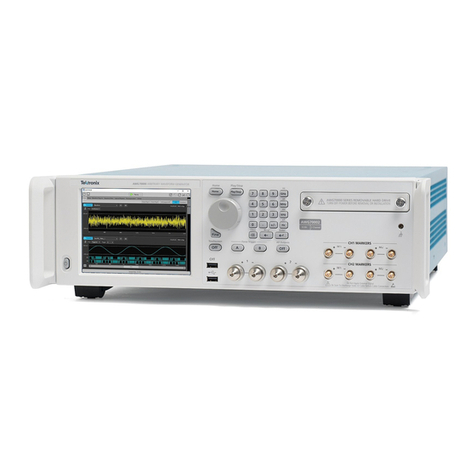
Tektronix DG2030 User manual

Tektronix

Tektronix DG2030 User manual
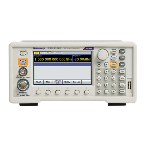
Tektronix AWG7000 Series Use and care manual

Tektronix

Tektronix AWG7000 Series Use and care manual

Tektronix AWG5200 Series Use and care manual

Tektronix

Tektronix AWG5200 Series Use and care manual

Popular Portable Generator manuals by other brands

Champion Power Equipment 100519 Operator's manual

Champion Power Equipment

Champion Power Equipment 100519 Operator's manual

Honeywell 0061520 owner's manual

Honeywell

Honeywell 0061520 owner's manual

Polysoude PS 254 Operating, programming and maintenance manual

Polysoude

Polysoude PS 254 Operating, programming and maintenance manual

Onan 12.0 RDJC Series installation guide

Onan

Onan 12.0 RDJC Series installation guide

GENERGY GZE-2020R manual

GENERGY

GENERGY GZE-2020R manual

iPower GXS10500RTC quick start guide

iPower

iPower GXS10500RTC quick start guide

Mase FM 50H Use and maintenance manual

Mase

Mase FM 50H Use and maintenance manual

EINHELL TC-PG 10/E5 operating instructions

EINHELL

EINHELL TC-PG 10/E5 operating instructions

Westinghouse WH10000DF user manual

Westinghouse

Westinghouse WH10000DF user manual

DENQBAR DQ-3600ER Original manual

DENQBAR

DENQBAR DQ-3600ER Original manual

Wiltron 681 A Series Operation manual

Wiltron

Wiltron 681 A Series Operation manual

Keysight M9484C Getting Started and Troubleshooting Guide

Keysight

Keysight M9484C Getting Started and Troubleshooting Guide

Keysight Technologies B2960A Demo guide

Keysight Technologies

Keysight Technologies B2960A Demo guide

Scheppach SG1600i instruction manual

Scheppach

Scheppach SG1600i instruction manual

Stanley GT23 user manual

Stanley

Stanley GT23 user manual

Keysight Technologies B2961A Demo guide

Keysight Technologies

Keysight Technologies B2961A Demo guide

Westinghouse WGen3600DF user manual

Westinghouse

Westinghouse WGen3600DF user manual

ScienTECH Caddo 4065 operating manual

ScienTECH

ScienTECH Caddo 4065 operating manual

manuals.online logo
manuals.online logoBrands
  • About & Mission
  • Contact us
  • Privacy Policy
  • Terms and Conditions

Copyright 2025 Manuals.Online. All Rights Reserved.