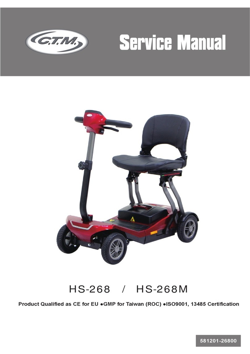
Toyhouse Daisy User manual

TOYHOUSE
User's Manual
DAISY SCOOTER
Item Code: 158900
Please read this manual carefully before assembly and use!

1.To move forward, press the left hand switch to'F'and press the right hand foot pedal.
2.The speed can be restricted by setting the right hand switch to'low'.
Maximum Speed: 6km/h.
3. To reverse, switch the left hand switch to'R'and press the right hand foot pedal.
4. Reverse only has one preset speed.
5. To stop, release the right hand foot pedal and press the left hand foot pedal.
RIDING INSTRUCTIONS
High/Low speed switch
IMPORTANT: Do not change direction ('F'to'R'or'R'to'F') when the vehicle is in motion.
Forward/Backward switch
Front lamp switch Horn switch
SAFETY WARNING
1. Suitable for children aged between 3-7 years old.
2. Maximum weight: 30kg-never overload.
3. Only one child to use the vehicle at a time.
4. Children must be under adult supervision at all time when using the vehicle.
5. Do not operate the vehicle on wet, sandy or, grass uneven ground conditions,
6. Protect the car from rain, splashes of water and moisture.
7. The children's vehicle dose not conformed the highway code requirements and for this reason,
cannot be used on roads for public traffic, please make sure that your child drives the vehicle
along suitable private roads, away from stairs or dangerous slopes.
8. Please keep the packing and instructions for future reference as they contain important
information.
Page 1

Page 2
1.Carefully unpack and identify all parts - see parts below.
ASSEMBLY
ATTENTION: This toy must be assembled by adults only.
A. Vehicle Body
B. Handlebar
C. Left/Right Front Wheel Covers
D. Wheel
E. Backrest
F. Front Fork
G.Lock Washer x2
H. Nylon Nut x2 & larger M 19x1
I. FrontAxle
J. Washer x2
K. Sleeve x2
L. Screw x4
Right cover Left cover

Page 3
Fig. 1
Fig. 2
Fig. 3
Fig. 5
Fig. 6 Turn 90°
Fig. 7
Turn back 90°
Fig. 4
3. lnsert the Front Fork (F) into the Vehicle
Body (A), see Fig.2.
2. Take the Vehicle Body (A), see Fig.1.
7. Turn 90 clockwise afterward to original
position, see fig.7. To secure the Front (F)
and the Handlebar (B) together, use the
large M19 Nut (H) on the part of the
handlebar (B) that protrudes out from the
Front Fork (F), see the line drawing next
to Fig.7.
NOTE:
- Ensure of 'V' arrow on the stem points
towards the rear of the vehicle body.
4. lnsert the Handle bar (B), part way into the
head of the Vehicle Body (A) and into the
Front Fork (F), see Fig.3.
5. Take the two wires protruding from the
Vehicle Body (A) and feed them through the
oval hole in the handlebar plate, see Fig.4.
Connect these wires to the pre-fitted wires
on the Handlebar (B), see Fig.5.
6. lnsert the Handlebar (B)When the handle
bar cannot into the Vehicle Body. (A)Pass
through, turn 90 anti-clockwise and push
to the lowest position, see Fig.6.
(9)Thread front fork though the hole
of front mudguard as the figure
shown and screw it with nut M19.
Handlebar
Front fork
(8)Thread handlebar through
the hole of front fork as the
figure shown.
Front fork
Front
mudguard
Nut M19

Page 4
Fig. 8
Fig. 9
Fig. 10
Fig. 11
Fig. 12
Fig. 13
NOTE:
NOTE:
10. Secure this in place by fitting a Lock Washer (G), followed
by a small Washer (J) and then a Nylon Nut (H), on both
sides, see Fig.10.
8. Feed the Front Axle (l) through the Wheel (D). On both sides
of the axle, slide a Sleeve (K), see Fig.8.
9. Slide this assembly part between the Front Forks (F),
see Fig.9.
- Ensure that the Lock Washer (G) is fitted correctly, with the
lock washer lip in the closed rectangular slot.
- Tighten the Nylon Nut (H) until the thread of the axle bites
onto the plastic ring of the nut.
11. Take the Left and Right Front Wheel Covers (C) and use
screws (L), two on either side, to secure them into place
on the Front Fork (F).
12. Finally take the Backrest (E), and fit it in place by matching
the holes with the spring buttons, see Fig.12.
- Please refer to the front cover of the manual to differentiate
between the Left and Right Cover.
CONNECTING THE ELECTRICS AND BATTERY
FOR
13. Raise the saddle, it pivots at the front.
Battery
connector Charger DC joint

Page 5
NOTE:
Battery
connector Charger DC joint
Power input: AC 230V - 240V.
Power: 2xDC 6V 10 AH Rechargeable Battery.
Charging Time: 8-12 Hours.
DO NOT CHARGE FOR LONGER THAN 15 HOURS ATATIME.
Lifetime: 300 recharges approx.
14. Fit the motor connector plug to the battery connector plug,
see Fig.13.
15. Replace the saddle.
CHARGING THE BATTERY
ATTENTION: The charger is not a toy and must only be used by an adult.
1. Raise the Saddle.
2. Disconnect the motor connector plug from the battery connector.
3. Connect the charger connector plug to the battery connector.
4. After charging reconnect the battery to the motor connector.
5. Replace the Saddle.
1 . Charge for 8-12 hours before first use.
2. The charger must only be used indoors.
3. The charger may get warm during charging.
4. Keep children away from the charger when charging the vehicle.
5. To extend the life of the battery, recharge after every use.
6. lt is advisable to recharge the battery when the vehicle starts to slow down, this will also
extend the life of the battery.
7. lf not use for 3 months, the battery should be charged again.
8. Store both charger and spare fuses carefully for future use.

Page 6
1. This product has a warranty period of 6 months from the date of purchase.
2. lf any defects become apparent during this time period caused by defective materials or
workmanship the retailer shall decide whether to repair or replace the product or refund
the purchase price.
3. Proof of purchase must be present when making a warranty claim, so keep your receipt safe.
4. This warranty dose not extend to damage caused by:
MAI NTENANCE
Regularly check the conditions of the vehicle, particular the steering column, electrical
installation and check that all wearable parts are sound.
CLEANING
The surface of the vehicle should be cleaned with a damp cloth; only an adult should do this.
TROUBLE SHOOTING
1. The vehicle does not go:
- Check that the battery and motor connectors are correctly assembled.
- Unscrew the battery securing clamp check the 25 amp fuse fitted to the caps on both
batteries. Replace any failed fuse.
- Carefully remove the cap from each battery and check that the battery terminals are
correctly connected. (See below'HOW TO CONNECT THE BATTERIES')
2. The vehicle goes very slowly:
- Fully recharge the battery f or 15hours maximum.
3. The battery cannot be fully charged:
- The fuse may be damaged: if damaged, replace with a fuse.
- The charger or battery may be damaged.
HOW TO CONNECT THE BATTERIES
- lf the batteries are disconnected, connect the red wire to the positive terminal and the black
wire to the negative terminal of either of the batteries.
- Connect the white wire to the positive terminal and the brown wire to the negative terminal
of the second battery.
EXCHANGE AND REFUND POLICY
5. Please contact the store where the item was purchased if you wish to make a warranty
claim. This does not affect your statutory rights.
- lncorrect assembly.
- Unauthorised work on the product.
- Normal wear and tear.
- lnappropriate use of the product.

Page 7
Batteries should not be disposed of in unsorted municipal waste, but separately collected to
facilitate the correct treatment and recycling of the substances they contain. The recycling of
batteries ensures the recovery of these valuable materials and prevents any potentially harmful
effects upon both the environment and human health. Please contribute to battery recycling
by segregating all spent batteries and actively participating in their collection and recycling.
Various battery collection schemes will be in operation in different areas of the country.
However, battery collection bins will be available at retail stores that sell batteries as well as
at schools, libraries and other public buildings.
Information on Waste Disposal for Consumers of Electrical & Electronic
Equipment
This mark on a product and/or accompanying documents indicates that
when it is to be disposed of, it must be treated as Waste Electrical &
Electronic Equipment (WEEE). Any WEEE marked waste products must
not be mixed with general household waste, but kept separate for the
treatment, recovery and recycling of the materials used.For proper
treatment, recovery and recycling; please take all WEEE marked waste
to your Local Authority Civic waste site, where it will be accepted free of
charge.If all consumers dispose of Waste Electrical & Electronic Equipment correctly, they
will be helping to save valuable resources and preventing any potential negative effects upon
human health and the environment, of any hazardous materials that the waste may contain.
Please Recycle Your Spent Batteries
Table of contents


