Toyo CV-3010 User manual

SERIAL to BCD CONVERTOR
MODEL CV-3010
OPERATION MANUAL
TOYO SOKKI CO.,LTD.
964-24 Nippa-cho Kohoku-ku, Yokohama 223-0057 Japan
TEL +81-45-540-8353
FAX +81-45-544-8354
MA4-00300-R1(2023/5)

MA4-00300-R1
- 2 -
-- Table of contents -- Page
§1. SUMMARY ..................................................................................................... 3
§2. APPEARANCE AND EACH PART NAME.................................................................. 3
§3. FUNCTION & OPERATION ................................................................................. 4
3-1) General .................................................................................................... 4
3-2) Input / Output interface .............................................................................. 4
3-3) Each function ............................................................................................ 5
3-4) Timing of acquisition of BCD data ................................................................. 7
3-5) Operation at abnormal ................................................................................ 8
§4. TROUBLESHOOTING........................................................................................ 9
4-1) Basic check point ....................................................................................... 9
4-2) Troubleshooting when the desired operation cannot be achieved. ....................... 9
§5. METHOD OF INSTALLATION AND CONNECTION .................................................. 10
5-1) Installation environment of this unit ............................................................ 10
5-2) Terminal/Connector connection .................................................................. 10
5-3) Precautions of wiring ................................................................................ 11
§6. DIMENSIONAL DRAWING ............................................................................... 12
※This operation manual is applied to the product shipped after Sep/2015
Revision history:
Rev.1 (2/Oct/2015)
Addition of explanation of Connectable indicator,
Details of I/F and Pulse width of STROBE signal
Rev.2 (26/May/2023)
Revision of explanation of Connectable indicator
This document is translated from MA4-00148-R2 (Japanese)

MA4-00300-R1
- 3 -
§1.Summary
This unit is a convertor to transform serial data which are transmitted from TOYO digital
indicator to BCD data. BCD data is output through Open Collector signal which is isolated from
an inner circuit by a photo coupler.
This unit has functions of Data hold and Logic inversion, etc. which are controlled by external
command input.
The power supplied voltage is DC24V which is isolated from an inner circuit by insulated DC/DC
convertor.
§2.Appearance and Each part name
Appearance of the unit
① SERIAL MONITOR (LED) LED for indicating that serial data is transmitting/receiving
② TERMINAL 5mm pitch screw-less terminal for serial I/O and power line
③CONNECTOR 36pin-Amphenol for BCD output and external command input
④ MOUNTING HOLE Use 4-M3 screw to fix this unit
Attached accessories
① Operation Manual 1 copy
② Connector (DDK 57-30360 or the equivalent) 1 pc

MA4-00300-R1
- 4 -
§3.Function & Operation
3-1)General
This unit is a convertor to transform 0~20mA current loop(as ‘C/L’ thereafter) or RS-232C
serial data which are transmitted from TOYO digital indicator to BCD data which is output
through Open Collector signal.
1). Connectable digital indicators
TOYO’s digital indicator equipped with C/L or RS-232C output can connect to CV-3010.
・TOYO’s digital indicator equipped with C/L output as standard are:
DLS-5028A,DLS-5025B,DLS-5037,DLS-5026B,DLS-5031A
・TOYO’s digital indicator equipped with C/L output as option are:
DLS-5033A(OP-4),TI-703(OP-4)
・TOYO’s digital indicator equipped with RS-232C as standard is:
DLS-5031A
・TOYO’s digital indicator equipped with RS-232C interface as option. It should connect to
CV-3010 through C/L signal if equipped with C/L as standard:
DLS-5028A(OP-3),DLS-5025B(OP-3),DLS-5037(OP-3),DLS-5026B(OP-3),TI-703(OP-3)
Cable length of RS-232C should be less than 15m. But cable length of C/L signal is up to 100m
because C/L signal is transmitted by current.
Input signal to this unit is either C/L signal or RS-232C signal. Cannot accept both signal at the
same time.
To enable addition of external connected device, either C/L or RS-232C input serial signal is
delivered to output port of RS-232C and C/L terminal.
2). BCD signal and accompanied signal
BCD output is 24bit Open Collector signal which is isolated by photo coupler.
BCD data : 5digit (4bitx5), Polarity(+), Overflow
STROBE : Timing signal of acquisition data
RUN : Alert signal for power failure, detecting abnormal of input signal
Above data will be updated each time receiving data through C/L or RS-232C signal.
This unit accepts 4 input signals to control conversion.
Data Hold : Update of BCD data is hold
Logic inversion of data : Invert of BCD data, Polarity(+), Overflow
Logic inversion of STROBE : Invert of STROBE signal
Pulse width of STROBE : Pulse width of STROBE is 100msec or 20msec.
3-2)Input / Output interface
1). Serial data input (RS-232C or C/L)
Digital indicator equipped with C/L output is connected to C/L input of this unit.
Digital indicator not equipped with C/L output but RS-232C interface as option is connected to
RS-232C input of this unit
Receivable data protocol of RS-232C is fixed as the followings.
Communication speed 2400bps
Communication protocol Start-stop synchronous (Asynchronous)
Communication format Data bit:7bit, Stop bit:2bit, Parity:Even, Data:ASCII code
MA4-00300-R1
- 5 -
2). Serial data output (RS-232C or C/L)
When C/L signal or RS-232C signal is input to this unit, same signal is transmitted from both
C/L and RS-232C port of this unit, which help to add external connected devices. But when
receiving error has been detected, the detected data is not transmitted. (including: flaming
error, parity error, over-run error)
Transmitting data protocol of RS-232C is same as the receiving data protocol.
A serial signal monitor LED which places close to the input terminal is flushing when
transmitting/receiving a serial signal.
3). BCD data output
BCD data is output through 24bit Open Collector output, which consists of NPN transistor and
photo coupler, TOSHIBA TLP627, and is isolated from an inner circuit. BCD data are output
from 36pin-Amphenol connector, Emitter is common to pin#13,#14,#31 and #32 of the
connector.
Rated output is DC30V, 30mA (resistive load). Saturation voltage between Collector and
Emitter is 1.2V or less at the rated load.
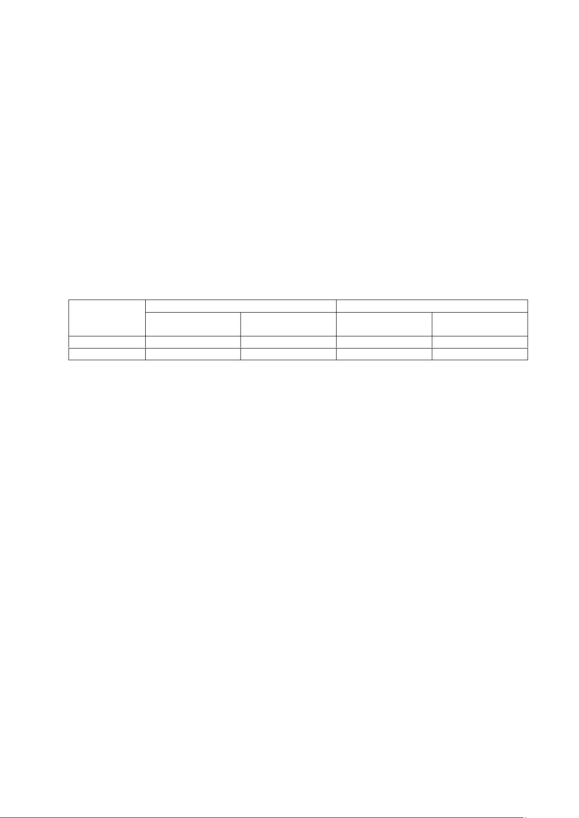
Output logic is selectable. Status between Collector and Emitter against negative/positive logic
are shown in a Table below.
Output data
Negative logic
Positive logic
Status Collector -
Emitter
Output level at
pull up end
Status Collector -
Emitter
Output level at
pull up end
0
Open
High
Short
Low
1
Short
Low
Open
High
4). External command input
There are 4 external commands, as Data Hold, Logic inversion of data, Logic inversion of
STROBE and Pulse width of STROBE, which are set by external Relay contact MAKE input. Each
contact current consumption should be approximately 5mA (at applied voltage 5V).
Ground of external input is common to the ground of inner circuit. The external Relay contacts
and this unit are supposed to build in the same control box, so that the cable length between
contacts and this unit should be less than 10m.
When the ground of external input is connected to Emitter of BCD output, external command
is not accepted because it is isolated from BCD output.
3-3)Each function
1). BCD data output
This unit outputs 5digit BCD signal which are converted from serial data of the measured value
comprised of ASCII code transmitted from TOYO’s digital indicator.
Decimal point is ignored if it is attached.
When a digital indicator indicates overflow, 4bit data of each digit output ‘1’. (5digit BCD
output ‘FFFFF’ in result). Using this function, it is possible to detect overflow without addition
of a bit as a discriminator.
2). Overflow output
When a connected digital indicator indicates overflow (All digits are flushing), output ‘1’.
3). Polarity output
Output ‘1’ when BCD data is plus.
Output ‘0’ when BCD data is minus.
4).STROBE output
BCD data is updated whenever the measured value data comprised of ASCII code is received .
STROBE signal is set ‘1’ after 10msec from when BCD data is updated and is set ‘0’ after
100msec after setting ‘1’.
Timing of acquisition of BCD data is to detect a rise edge of the STROBE signal first and capture
BCD data within 100msec.

MA4-00300-R1
- 6 -
5). RUN signal
RUN signal output ‘1’ after receiving the first serial data from powered ON.
All the most of TOYO’s digital indicator transmit data 4times/second or 16times/second. If
receiving data is stopped for 1 second, treat as abnormal of indicator or disconnection of cable,
RUN signal output ‘0’ until the next data is received.
Logic of RUN signal is fixed to the negative logic. Status between Collector - Emitter is OFF
when powered OFF. RUN signal can be used as detecting abnormal of indicator or power
failure.
6). Data Hold signal
When making electrical short between #16 and #18(D.COM) of 36pin-Amphenol connector,
update of BCD data is stopped within 50msec. BCD data and STROBE signal is not updated
while electrical short between them.
In case of being impossible to utilize STROBE signal, capture BCD data after 50msec from
when Data Hold signal is input to this unit.
7). Logic inversion of data signal
When making electrical short between #34 and #36(D.COM) of 36pin-Amphenol connector,
invert the logic of BCD data, Polarity, Overflow
Open : Negative logic (at the time of shipment)
Short : Positive logic
8). Logic inversion of STROBE signal
When making electrical short between #17 and #18(D.COM) of 36pin-Amphenol connector,
invert the logic of STROBE signal
Open : Negative logic (at the time of shipment)
Short : Positive logic
9). Pulse width changing of STROBE signal
When making electrical short between #35 and #36(D.COM) of 36pin-Amphenol connector,
pulse width of STROBE signal is changed.
Set 100msec when transmitting data of the connected digital indicator is 4 times/second.
Set 20msec when transmitting data of the connected digital indicator is 16 times/second.
Open : Pulse width 100msec. (at the time of shipment)
Short : Pulse width 20msec.
MA4-00300-R1
- 7 -
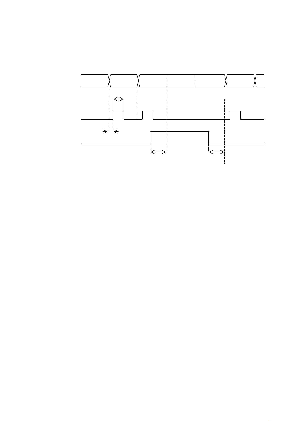
10ms
100ms (or 20ms)
50ms
max
50ms
max
250ms (or 60ms) update cycle
3-4)Timing of acquisition of BCD data
1). Timing chart of BCD data output sequence
This unit is operated according to the following timing at most cases.
After a serial data has been received, BCD data is updated.
After 10msec from an update of BCD data, STROBE signal is transmitted for 100msec or
20msec time length.
After 50msec from input of Hold signal, BCD data is hold and not updated. After 50msec from
release of Hold signal, BCD data is updated again.
2). Methods of acquisition of BCD data
BCD data is unstable during updating period. Transition time to turn ON of output transistor
(including photo coupler) is approximately tens of μsec. But transition time to turn OFF of it is
approximately up to hundreds of μsec depending on a load.
Transition time can vary depending on the individual of transistor or load differences or
surrounding temperature.
Thus, if connected equipment try to capture all the 24bit data at same time while data is
updating, it will result in capture data error.
For example, when capturing data while it is transiting from 19999 to 20000, BCD data might
be 29999 or 10000, which is capture data error.
To prevent such capture data error, please capture data by one of the following method.
① Method to utilize STROBE signal
STROBE signal is high level ‘1’ and BCD data is stable after 10msec from updating BCD data.
STROBE signal is ‘1’ for 100msec (or 20msec). Because an update data cycle of a connected
digital indicator is 250msec (or 60msec), after STROBE signal turns to low level ’0’ there is no
possibility to update the next data at least for 100msec (or 20msec).
Thus, to capture BCD data, first detect a rise edge of the STROBE pulse to ‘1’, and next capture
all the 24bit data within 100msec (or 20msec).
The value inside () is the one at pulse width of STROBE signal=20msec when transmitting data
of connected digital indicator is 16times/second.
This method makes the delay time of data acquisition be shortest compared to the other two
methods.
② Method to utilize Data Hold command
When making electrical short between #16 and #18(D.COM), update of BCD data is stopped
within 50msec and BCD data is stable.
After 50msec from input of Data Hold command, capture all the 24bit data.
BCD data
STROBE signal
Hold signal

MA4-00300-R1
- 8 -
③Method to capture data more than 2 times
Capture all the 24bit data 2 times with interval more than 10msec. Compare both data and if
they coincide, regard as correct data. If not coincide, consider that the first data is captured
before update and the second data is captured after update, or data are captured while in
transition state of unstable. In that case, capture data again after 10msec or more.
Use this method, capturing data at least 3 times, judge the correct data to prevent a capture
data error.
3). Recommended logic and RUN signal
This unit can invert output of BCD data (5digit data, polarity (+), over) and STROBE signal
independently.
Because BCD data is output by Open Collector, status between Collector–Emitter is OFF when
powered OFF. Thus, it is recommended to use negative logic of both BCD data and STROBE
signal.
When using positive logic, it is impossible to distinguish the state of plus side overflow (5digit
data and polarity are all ‘1’) and state of powered OFF. Also STROBE signal becomes ‘1’ when
powered OFF.
If using positive logic, it is recommended to utilize RUN signal. Status between
Collector-Emitter of this signal is OFF only when powered OFF or receiving data from digital
indicator is stopped for more than one second. Treat RUN signal as an alert to help to prevent
such trouble.
When using negative logic, to monitor RUN signal, it is easy to detect an alert.
3-5)Operation at abnormal
All the 24bit output between Collector-Emitter are OFF when powered OFF, also they are OFF
until the first serial signal coming in from powered ON.
When receiving data is stopped for more than 1 second caused by disconnection of cable or
receiving error, BCD data output ‘-00000’ regardless specified logic. Because zero output from
digital indicator is only ‘+0’, it is easy to distinguish that ‘-0’ is abnormal. STROBE signal is not
output in this case. RUN bit between Collector-Emitter is OFF

MA4-00300-R1
- 9 -
§4.Troubleshooting
If this unit does not work properly, please take the following measures. If the trouble still
cannot be solved, then please contact our company.
At query, please inform us the model name, product serial number, and conditions of this unit
as detailed as possible.
4-1)Basic check point
1). Please check if using a correct power supply.
This unit is supplied voltage with DC24V±10% (100mA typ.).
2). Please check that wires are connected to the terminal and connector properly and firmly.
4-2)Troubleshooting when the desired operation cannot be achieved.
1). Check input of serial signal
Check whether the serial signal monitor LED is flushing regularly. That LED is blinking
ON/OFF 4 times per second when the serial data is received normally.
When the LED is not flushing, please check the wiring of input signal of the terminal. Check
whether there is no disconnection of wires or each signal line of RS-232C or C/L is wired to
appropriate terminal.
C/L signal has no polarity.
Check whether RXD and D.COM of RS-232C signal is wired correctly.
Either RS-232C or C/L should be connected to the input terminal. If both are connected, it
is unable to receive serial data.
2). BCD data is not output even the serial monitor LED is flushing.
Check the subsequent wiring of BCD output. It is unable to detect ON/OFF of Emitter –
Collector by a tester because it is Open Collector output.
Each output of Collector side should be connected to the plus side of external DC supply
through a load. Each output of Emitter side should be connected to the minus side of
external DC supply.
Also check whether the external DC supply is satisfied with the rated output of photo
coupler in this unit. (Max. DC30V, 30mA, resistive load).
3). BCD data does not coincide with data of connected digital indicator all the time, or several
times in a day.
① Check the logic inversion of BCD data (Negative logic at the time of shipment).
② Check the logic inversion of STROBE signal (Negative logic at the time of shipment).
③ When capturing BCD data without condition, capture it when it is stable by using the
method of 3-4) 2). ‘Methods of acquisition of BCD data’
MA4-00300-R1
- 10 -
§5.Method of Installation and Connection
5-1)Installation environment of this unit
1) Operation temperature range of this unit is 0 to +40℃.
Please install this unit in a place not exposed to direct sunlight and condensation.
Consider ventilation when installing inside a control box which has possibility of filled up
heat. (This unit does not generate large amount of heat by itself)
2) The power supplied voltage is DC24V±10%.
Using an improper power supply may cause overheating, damage, malfunction, etc.
3) This unit is designed to fix by wall-mount. Please make use of holes 4-Φ4.0 of a cover and
fix with M3 screw.
There is no restriction of installation of direction.
5-2)Terminal/Connector connection
Serial signal is wired to 5mm pitch, 12pin screw-less terminal.
The shield line of each cable shall be grounded by either this unit or each connected
instrument, so that there is no ground loop.
Terminal #9(Shield) and #10(E) are connected inside of this unit.
Power supplied voltage is DC24V, which is isolated from an inner circuit by DC/DC
converter.
Serial signal from a digital indicator should be wired to the terminal as follows
・C/L signal C/L signal from a digital indicator is wired to the terminal
#1,#2 (C/L input), with no polarity.
・RS-232C signal TXD signal from a digital indicator is wired to the terminal
#5 (RXD).
COM signal from a digital indicator is wired to the terminal
#6 (D.COM).
Open Collector output is isolated from an inner circuit by photo coupler.
External command input, RS-232C input and C/L input are not isolated from inner circuit.
Ground of external input is common to the ground of RS-232C input. Thus it is
recommended to prepare external Rely contact to drive external input of this unit.
Meanwhile, C/L output of this unit is isolated from an inner circuit by photo coupler.
Wiring to BCD data connector should be done through a shielded cable.
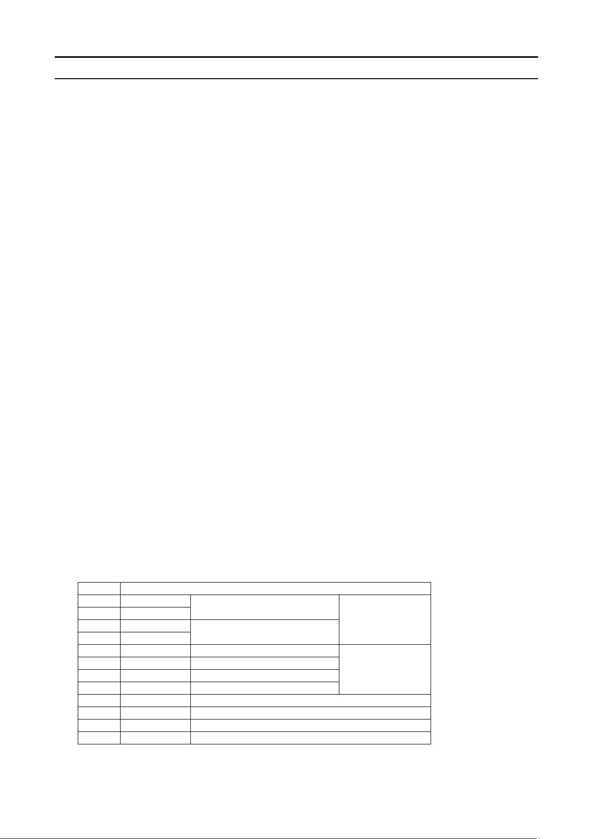
1). Terminal
5mm pitch, 12pin screw-less terminal
No.
Connection signal
1
C/L IN
C/L signal input
(No polarity)
Current Loop
2
C/L IN
3
C/L OUT
C/L signal output
(No polarity)
4
C/L OUT
5
RXD
Receive data
RS-232C
6
D.COM
Digital ground
7
TXD
Transmit data
8
D.COM
Digital ground
9
Shield
Shield of serial signal
10
E
Earth / Ground
11
+24V
Power line (DC+24V)
12
0
Power line (DC+0V)
Applicable wire spec.: Single wire = Φ0.4~1.2mm (AWG26~16),
Strand wire = 0.3~1.25mm2(AWG22~16)

MA4-00300-R1
- 11 -
2). Connector
36pin connector, DDK : 57-40360-7700(D12) or the equivalent
Direction
Connection signal
No.
No.
Connection signal
Direction
OUT
BCD data 100-1
1
19
BCD data 100-2
OUT
BCD data 100-4
2
20
BCD data 100-8
BCD data 101-1
3
21
BCD data 101-2
BCD data 101-4
4
22
BCD data 101-8
BCD data 102-1
5
23
BCD data 102-2
BCD data 102-4
6
24
BCD data 102-8
BCD data 103-1
7
25
BCD data 103-2
BCD data 103-4
8
26
BCD data 103-8
BCD data 104-1
9
27
BCD data 104-2
BCD data 104-4
10
28
BCD data 104-8
OVER
11
29
POL(+)
STROBE
12
30
RUN
Common Emitter
13
31
Common Emitter
14
32
N.C.
15
33
N.C.
IN
Data Hold
16
34
Logic inversion of
Data
IN
Logic inversion of
STROBE signal
17
35
Pulse width changing
of STROBE signal
D.COM
18
36
D.COM
Applicable wire connector: DDK 57-30360 or the equivalent
Connector pin#18,36(D.COM) are common to the terminal#6,8(D.COM) of RS-232C serial
I/O, but are independent from pin#13,14,31,32(Common Emitter) of BCD data output.
5-3)Precautions of wiring
BCD data output of this unit is Open Collector output. External command input of this unit
should be driven by external Relay contact due to not isolated from an inner circuit. The
external Relay contacts and this unit are supposed to build in the same control box, so that the
cable length between Relay contacts and this unit should be less than 10m.
BCD data signal can be extended as long as 100m because they are isolated from an inner
circuit. But it will depend on the surrounding circumstances.
Micro
computer
BCD output
BCD output
Common Emitter
External
command input
External
command ground
Recommended external Relay contact
Rated out DC5V 10mA or more
OMRON MY2,MY4 etc.
(for DIN rail)
OMRON G5V-1, G6E etc.
(for mount on board)
MA4-00300-R1
- 12 -
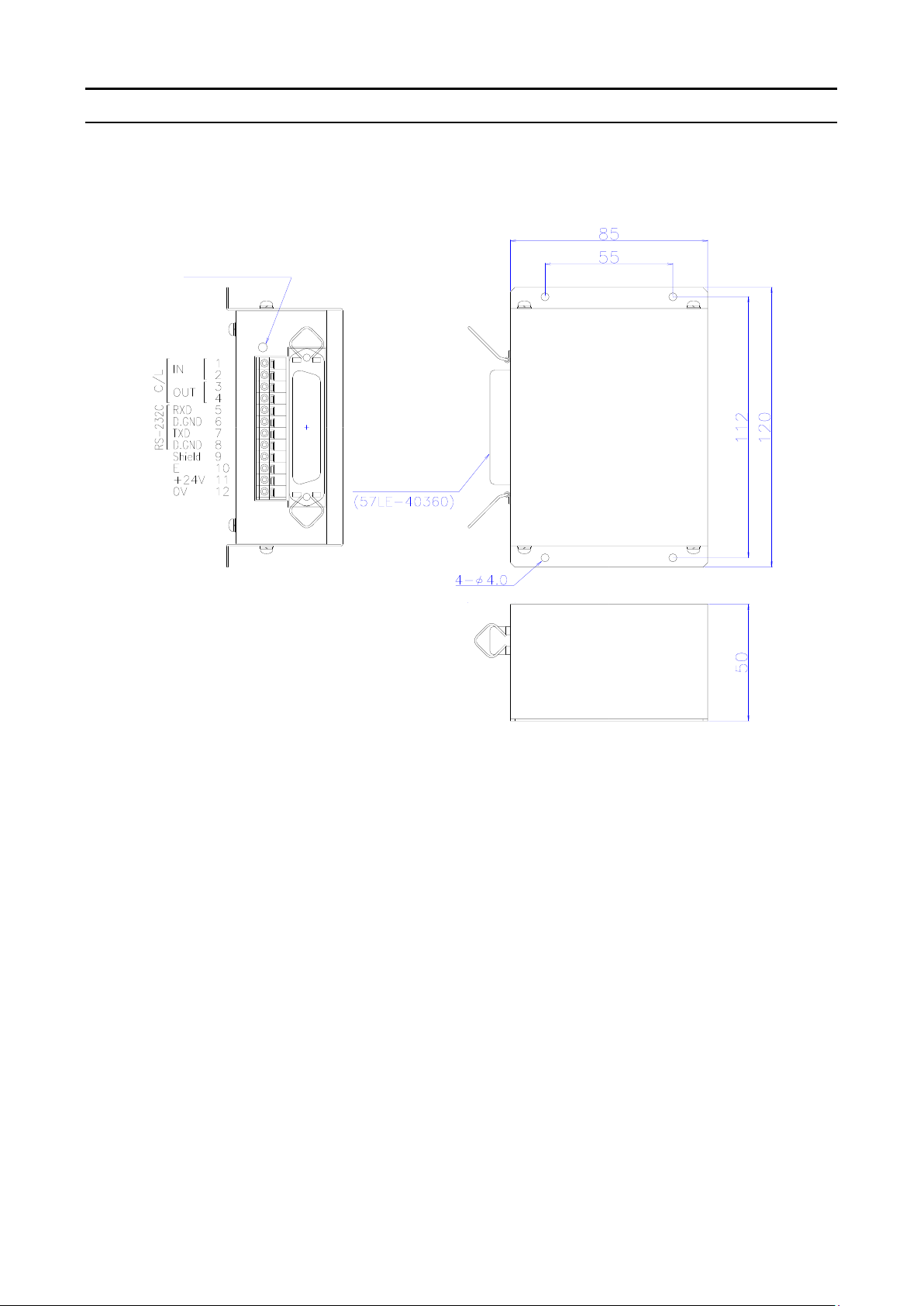
§6.Dimensional drawing
Serial data monitor LED
Connector for
BCD data output
Mounting hole
Table of contents


