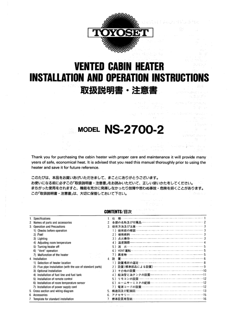
Toyoset NS-2700-2 Owner's manual

VENTED CABIN HEATER
INSTALLATION AND OPERATION
INSTRUCTIONS
MODEL NS-2700-2
Thank you for purchasing the cabin heater with proper care and maintenance it will provide many
years of safe, economical heat. It is advised that you read this manual thoroughly prior to using the
heater and save it for future reference.
Model NS-2700-2
Type Forced-flue (FF type), pot type
Ignition type Electric lighting (coil heater)
Fuel type Water-clear kerosene/Diesel oil
Heat rating High: 9,800BTU/h Low: 4,900BTU/h
Fuel consumption High:0.07gal/h Low: 0.04gal/hr
Heating efficiency Heating efficiency: Approx. 90%
Exterior dimensions
See figure on right ;
Weight Approx. (20LBS.)
Power source DC 12V
Power consumption Igniting: 78W (3min.)
Burning: High 18W
Burning: High 6W
Current fuse 10A
Safety devices Ignition safety device Igniter malfunction detector
Flame sensor
Overheat protector (High limit switch)
Power failure safety device
Burner bottom temp. sensor
Low/high/reverse voltage safety device
Flue pipe Inner nominal : 1 in. Outer nominal : 2in.
Air duct 2-3/16 in. (3 in.)
Ventilation capacity Approx. 2, 700FT


OPERATION AND PRECAUTIONS
1) CHECK BEFORE OPERATING
.Make sure that there is no oil leakage in the fuel feed line. Fuel is pumped through a
translucent hose from a tank mounted below the heater.
. Make sure also that there are no flammable objects close to the heater unit.
. Flue pipe must be installed in such a manner that it’s top exits outside.
. This heater is designed to use while lying at anchor.
. This heater is of the forced-flue type with separate flues for intake and exhaust.
Make sure that all the joints of the flue pipes are connected securely. Care must be taken
not to let exhaust gas into the rooms to insure safety.
2) FUEL
. This heater can be used with kerosene or diesel oil. However, use of kerosene is
recommended due to clean burning.
WARNING: Use only water-clear kerosene or diesel oil. Never use gasoline or other
flammable liquids. Never use fuel with a yellow color.
3) Lighting:
. Turn the operation switch to “ON”, so that the power lamp lights up and the igniter is
activated. In approximately six (6) seconds, the blower motor and fuel pump start up at
“LOW” mode for (2) minutes, regardless of temperature setting. Flame lamp lights up
while the heater is burning.
Note: The first time the heater is used or after running out of fuel, the fuel
Lines are empty and the fuel pump may cause an audible sound. If the
Unit shuts off, wait 2 minutes and restart.
Note: When you first use your heater, or fuel is out, fuel pump may produce
an audible operation noise at ignition. This is only temporary.
Note: You may observe some odor of adhesives for insulating materials at the
Beginning of use. But it will be moved for a couple of hours.
Caution: The blower motor repeats its “on and off” power from when the power “ON” switch is pressed to when the
“FLAME” lamp lights up. The fuel pump makes a slight vibration periodically (once or twice per second), which is of
no problem in design.
Caution: Too low a battery power may cause the stove difficult to be lit.
Caution: When igniting the flue pipe may release a white smoke outsides, with an offensive smell in the room.
Caution: Starting of the engine while the stove is in operation may lower the battery voltage all at once and, thereby
stop the stove operation.
Caution: Do not plug the circulation inlet and heated air outlet.
4) ADJUSTING ROOM TEMPERATURE:
. Burning mode will be automatically selected to maintain the desired room temperature
from five (5) minutes after ignition.
1. The temperature control will automatically regulated to maintain the desired
temperature setting.
2. Heater will burn at high combustion until room temperature reaches the setting
temperature. When room temperature reaches the desired setting, heater will

automatically shift to “LOW” mode. When the room temperature exceeds the
desired setting, heater will automatically shut off. As room temperature drops,
heater will automatically re-start to maintain desired setting.
Note: Burning condition can be observed through the peep window, so you
Can check it’s burning condition visually.
FLAME CONDITION
Normal – Blue flames
Abnormal - High yellow flames or flare up.
5) TURNING HEATER OFF:
Turn the operation switch to “OFF”, so “POWER” lamp and ”FLAME” lamp go off.
Blower motor keeps running to cool down the burner for two
minutes after turning off the switch.
Caution: No re-lighting operation can be given for two minutes
above.
Caution: Do not disconnect power supply to extinguish. Blower
motor must
Be in operation at least for two minutes to prevent the heater from
Overheating.
6) “VENT” OPERATION:
Air ventilation can be obtained without heat by using operating only the
Blower motor. “VENT” lamp will be lighted during operation.
Airflow in the “VENT” mode can be adjusted by sliding the temperature
Selector.
Note: “VENT”- operation can be also used to cool down the burner if
It becomes overheated just in case.
7) MALFUNCTION OF THE HEATER:
If a malfunction occurs, the heater will stop and the indicator lamps will flash.
The flashing lamps indicate the cause of the malfunction as shown here:
Malfunction Vent Power Flame
No ignition, no flame ☼
Burner bottom thermistor activated ☼☼
Igniter malfunction ☼☼
Power voltage is too high. (12V →more than 17V ☼☼
Power voltage is too low. (12V →less than 8.5V) ☼☼☼
ON/OFF switch vs on before power connected ☼☼☼
High limit switch activated. ☼

Option 1
The heater draws fresh air into a room with an exhaust vent.
Caution: If the heater blows heated air into a closed room without a vent
Opening, the heated air may not be circulated.
Option 2
The heater warms room air and recirculates it.
Option 3 Combination of options 1 and 2.

Note: Combined total of fresh air intake and heat air outlet pipe must not exceed 5 m or 16 –1/2 ft.

1) SELECTION OF HEATER MOUNTING
LOCATION:
. Select a location free of flammable objects.
The heater surfaces may get hot, so install the
heater in a location where it does not directly
touch the structure of the building, vessel, or it’s
surrounding equipment. It is also suggested that
the heater is installed in a place where it is not
subjected to direct seawater or rain.
. The heater should also be installed
approximately 20cm (8 in.) or more away from
the wall to allow enough room to use a
screwdriver for service and maintenance.
. The circulation air inlet and heated air outlet
cannot be changed.
Select location where these flows are not
obstructed.
. The heater is designed so that it can be
inclined. The basic installing angle must be
within +/- 5 degrees of level as illustrated in the
figure to the right.
. Combustion fresh air and exhaust gas pass
through “pipe-within-a-pipe” which consists of
two concentric tubes.
Do not install the flue pipe in close proximity to
flammable materials due to high temperature
(250 C or 480 F)
Side – not less than 30 cm (1ft.)
Top – not less than 1 m (3 ft.)
. Both intake and exhaust flue pipe openings
must be fully exposed to outside air.
. Install the flue pipe so that heavy rain or sea
water do not enter into the heater as it may cause the heater damage
A waterproof cap is available as an accessory. See page 15, the section of
“ACCESSORIES”.

2) FLUE PIPE INSTALLATION:
(Standard parts installation)
Remove the two hexagon bolts 8 and
washers 9 from the heater unit. Also
remove the hanger 7 from the heater
unit. First assemble the flue pipe 1 and
the hanger 7 and secure them as shown.
Make sure that the hanger 7 has been
securely mounted. Slide the heater in at a
slight angle to connect the flue pipe.
Connect and secure the heater to the
hanger 7 with the two hexagon bolts 8
and washers 9 tighten firmly.
Note: The bulkhead or overhead
thickness should not exceed 50 mm (2
in.). If it is over 50 mm (2 in) another
method should be used.
Caution: Do not secure the hexagon bolt
8 too tight.
1. Flue pipe
2. Bolt 4pcs.
3. Flue pipe packing
4. Washer 8pcs.
5. Nut 8pcs.
6. Spacer
7. Hanger
8. Hexagon bolt 2pcs
9. Washer 2pcs.

3) OPTIONAL INSTALLATION:
(Using extension pipe NSP-11or NSP-15)
Use template for installation of the flue pipe
on page 16.
Parts 11 to 16 are enclosed with extension
pipe set (NSP-11 or NSP-15)
First assemble the flue pipe 1 with hexagon
bolts {1 or 11}.
Next remove two hexagon 8 and washers 9
from the heater unit and remove the hanger
7. Attach the hanger 7 to wall surface by
using wood screws 10.
Then hook the heater unit to the hanger and
insert the hexagon bolts 8 and washers 9.
Connect the flue pipe 1 and the heater unit
with extension pipes.
(See page 15 for “ACCESSORIES”).
Note: Flue pipe can be installed on the
bulkhead or overhead thickness up to 75 mm
(3 in.).
Important: The extension pipe can be
extended up to 1.5 m (5 ft.) long with no
more then two bends.
Note: The NSP-11 pipe can be set at 0.5 m
(20 in.), 1 m (3-1/4 ft.) and 1.5 m (5 ft.)
length. The shortest possible connection is
recommended.
The NSP-15 is set only at 0.5 (20 in.),
length.
10. Wood screw 4pcs
11. Bolt 4pcs.
12. Pipe band 2pcs.
13. Pipe holder 2pcs,
14. Flexible exhaust pipe
15. Flexible intake pipe
16. Self tapping screw 1pc.

4) INSTALLATION OF FUEL TANK AND
FUEL LINE:
Parts 21 through 24 are supplied with the
heater. Remove the protective cap provided
on the “IN” side of the fuel pump. Insert cap
nuts 22 and sleeves 23 into fuel line 21, as
shown in the figure. Next firmly push fuel
line 21 into fuel pump inlet, and securely
fasten the pipe with the cap nut 22.
Caution: Fuel line is to be a maximum of
1.5m (5 ft.).
Caution: Be sure the fuel line is the proper
length and the fuel tank is below the heater.
Important: Fuel tank must be secure to
prevent movement.
Caution: Remove any dust from the fuel
line inlet before installing the fuel line. It
may cause a fuel pump malfunction.

5) INSTALLATION OF REMOTE CONTROL:
Remove self-tapping screw 31 from the controller. Attach
the metal fitting 33 with a wood screw 32 and then re-
assemble remote control with self-tapping screws 31.
Note: The lead wires for remote control is 2.5 m (8-1/5 ft.)
in length.
Note: The lead wire for the remote control can be
connected to the top or bottom of the unit. Or the wiring
can be installed through a wall by using option parts.
Note: Remote control can also be mounted on the heater at
the positions indicated below.
6) INSTALLATION OF ROOM TEMPERATURE
SENSOR:
The room temperature sensor can be installed either with the self adhesive tape on the back
or with a wood screw provided with the sensor depending on the type of surface.
a. Self adhesive tape
Peel off the protective tape on the back of the sensor and expose
the adhesives. Place the sensor on the desired location on the
wall and press down.
b. Wood screw
Screw down the wood screw provided with the heater into the
desired location on the wall. Hook the back of the room
temperature sensor.
7) INSTALLATION OF POWER SUPPLY CORD:
The power supply cord is approximately 2.5 m (8-1/5 ft.) in. length. Be careful not to
misconnect positive (+) and negative (-) terminals. A 10A fuse is used for heater.
Black cord: Positive (+)
White cord: Negative (-)
Note: In case of using extension cord, always minimize the length as short as possible. Use
of extension cord too long may occur ignition failure due to drop of voltage.

Other manuals for NS-2700-2
1
Table of contents
Other Toyoset Heater manuals
Toyoset
Toyoset Omni 230 Troubleshooting guide

Toyoset
Toyoset Radiant 100 User manual

Toyoset
Toyoset SRE 725 User manual

Toyoset
Toyoset Radiant 101 Troubleshooting guide

Toyoset
Toyoset Radiant 101 User manual

Toyoset
Toyoset Omni 200 User manual

Toyoset
Toyoset Omni 230 Type C Troubleshooting guide

Toyoset
Toyoset SRE 115 C User manual

Toyoset
Toyoset RCA-2800 Troubleshooting guide
Toyoset
Toyoset NS-2700-2 User manual