manuals.online logo
Brands
  1. Home
  2. •
  3. Brands
  4. •
  5. TP-Link
  6. •
  7. Network Router
  8. •
  9. TP-Link Omada SG2005P-PD User manual

TP-Link Omada SG2005P-PD User manual

Other TP-Link Network Router manuals

TP-Link Archer AX55 User manual

TP-Link

TP-Link Archer AX55 User manual

TP-Link Archer C20 User manual

TP-Link

TP-Link Archer C20 User manual

TP-Link tl-wr845n User manual

TP-Link

TP-Link tl-wr845n User manual

TP-Link Archer C7 Setup guide

TP-Link

TP-Link Archer C7 Setup guide

TP-Link Deco WE10800 User manual

TP-Link

TP-Link Deco WE10800 User manual

TP-Link TD-8841 User manual

TP-Link

TP-Link TD-8841 User manual

TP-Link Archer C6 User manual

TP-Link

TP-Link Archer C6 User manual

TP-Link Archer VR600 User manual

TP-Link

TP-Link Archer VR600 User manual

TP-Link SafeStream TL-ER6020 User manual

TP-Link

TP-Link SafeStream TL-ER6020 User manual

TP-Link Archer C7 User manual

TP-Link

TP-Link Archer C7 User manual

TP-Link TD-W9960v User manual

TP-Link

TP-Link TD-W9960v User manual

TP-Link TL-R410 User manual

TP-Link

TP-Link TL-R410 User manual

TP-Link TL-WR810N User manual

TP-Link

TP-Link TL-WR810N User manual

TP-Link Archer AC1200 User manual

TP-Link

TP-Link Archer AC1200 User manual

TP-Link Deco BE65 User manual

TP-Link

TP-Link Deco BE65 User manual

TP-Link SafeStream TL-R600VPN User manual

TP-Link

TP-Link SafeStream TL-R600VPN User manual

TP-Link AC1600 User manual

TP-Link

TP-Link AC1600 User manual

TP-Link TPL-WR941HP User manual

TP-Link

TP-Link TPL-WR941HP User manual

TP-Link TD-8816 User manual

TP-Link

TP-Link TD-8816 User manual

TP-Link RE200 User manual

TP-Link

TP-Link RE200 User manual

TP-Link JetStream TL-SL3428 User manual

TP-Link

TP-Link JetStream TL-SL3428 User manual

TP-Link Archer C60 AC1350 User manual

TP-Link

TP-Link Archer C60 AC1350 User manual

TP-Link Omada Pro 4G+ User manual

TP-Link

TP-Link Omada Pro 4G+ User manual

TP-Link SafeStream TL-R480T+ User manual

TP-Link

TP-Link SafeStream TL-R480T+ User manual

Popular Network Router manuals by other brands

TRENDnet TEW-435BRM - 54MBPS 802.11G Adsl Firewall M Quick installation guide

TRENDnet

TRENDnet TEW-435BRM - 54MBPS 802.11G Adsl Firewall M Quick installation guide

Siemens SIMOTICS CONNECT 400 manual

Siemens

Siemens SIMOTICS CONNECT 400 manual

Alfa Network ADS-R02 Specifications

Alfa Network

Alfa Network ADS-R02 Specifications

Barracuda Networks Link Balancer quick start guide

Barracuda Networks

Barracuda Networks Link Balancer quick start guide

ZyXEL Communications ES-2024PWR Support notes

ZyXEL Communications

ZyXEL Communications ES-2024PWR Support notes

HPE FlexNetwork 5510 HI Series Openflow configuration guide

HPE

HPE FlexNetwork 5510 HI Series Openflow configuration guide

Allied Telesis AT-AR236E quick start guide

Allied Telesis

Allied Telesis AT-AR236E quick start guide

ADTRAN NetVanta 3458-PoE quick start

ADTRAN

ADTRAN NetVanta 3458-PoE quick start

C&H Technologies EM405-8 manual

C&H Technologies

C&H Technologies EM405-8 manual

Huawei WiFi Mesh 3 Product description

Huawei

Huawei WiFi Mesh 3 Product description

Addonics Technologies ISC8P2G-S Quick install guide

Addonics Technologies

Addonics Technologies ISC8P2G-S Quick install guide

Atel W02 Arch+ Faqs

Atel

Atel W02 Arch+ Faqs

Allnet ALL0333AU user guide

Allnet

Allnet ALL0333AU user guide

Sercomm Genesis OC3505D Quick installation guide

Sercomm

Sercomm Genesis OC3505D Quick installation guide

Billion BIPAC 5102 Series user manual

Billion

Billion BIPAC 5102 Series user manual

Motorola MR1900 user guide

Motorola

Motorola MR1900 user guide

Cisco SOHO Series Regulatory compliance and safety information

Cisco

Cisco SOHO Series Regulatory compliance and safety information

NETGEAR WGE101 Reference manual

NETGEAR

NETGEAR WGE101 Reference manual

manuals.online logo
manuals.online logoBrands
  • About & Mission
  • Contact us
  • Privacy Policy
  • Terms and Conditions

Copyright 2025 Manuals.Online. All Rights Reserved.

© 2023 TP-Link 7106510686 REV1.0.3
Omada Gigabit Smart PoE++ in and PoE+ out Switch
Conguration
Connection
LED Explanation
On: The remaining PoE power is ≤ 7 W
Flashing: The remaining PoE power keeps ≤ 7 W
for more than 2 minutes
O: The remaining PoE power is > 7 W
PoE MAX
PoE Status
For Port 1-4
On: Providing PoE power
Flashing: Current-overload/Short-circuit/Connected
to a non-standard PD/Power exceeded the
user-dened value
O: Not providing PoE Power
For Port 5*
On (Green): Powered by 802.3bt
On (Yellow): Powered by 802.3af/at
O: Power o
*The LED will be on after port 5 is connected to a PoE Power Sourcing
Equipment (PSE) for 2-3 seconds.
The switch supports two conguration methods:
Standalone Mode: Congure and manage the switch singly.
Controller Mode: Congure and manage the network devices centrally. It is recommended in the large-scale network, which consists of mass devices such as
access points, switches, and gateways.
Note: When the switch is changed from Standalone Mode to Controller Mode, congurations of the switch will be lost. For details, refer to the related documents on the download center of our
ocial website: https://www.tp-link.com/support/download/.
Quick Installation Guide
On/O: System running abnormally
Flashing: System running normally
System
On (Green): Connected to a 1000 Mbps device
On (Yellow): Connected to a 10/100 Mbps device
Flashing: Transmitting/receiving data
O: No device is connected to the corresponding
port.
Link/Act
IP Camera AP IP Phone
Ethernet Ports (1-5)
PoE OUT (1-4)
Powered Device (PD)
Router
LAN Port WAN Port
Internet
PSE
(e.g. PoE Switch, PoE Injector)
Note:
1. SG2005P-PD does not support DC or AC power input. A PSE device needs to be connected to the PoE IN port to provide power for
SG2005P-PD.
2. The PoE OUT ports can also be connected to non-PoE devices, but only transmit data.
3. Maximum PoE power is 30 W for each PoE port, and 6 W/ 19 W/ 44 W/ 64 W PoE power budget for all PoE ports when powered by
802.3af (type 1)/ 802.3at (type 2)/ 802.3bt (type 3, 60 W)/ 802.3bt (type 4, 90 W) respectively.
4. PoE budget calculations are based on laboratory testing. Actual PoE power budget is not guaranteed and will vary as a result of
client limitations and environmental factors.
Mounting
Note: The switch can be pole-mounted or wall-mounted. Follow the steps below for the appropriate installation and make sure the switch is installed with its ports facing down.
Method 1: Pole Mounting
1. Lead the end of the pole mounting strap through the back of the mounting
bracket.
2. Fix the mounting bracket on the pole and fasten the strap, then secure the
switch into the mounting bracket as shown below.
Method 2: Wall Mounting
1. Place the mounting bracket in the right position. and mark four positions for
the screw holes. Drill four 6 mm holes at the marked positions, insert the
anchors into the holes, align the bracket to the anchors and drive the
self-tapping screws into the anchors through the bracket.
2. Align the mounting bracket and the switch, and secure the switch into the
mounting bracket as shown below.
Mounting
Bracket
ScrewsAnchorsPosition Label
1 2
PoE OUT PoE IN
345
Reset
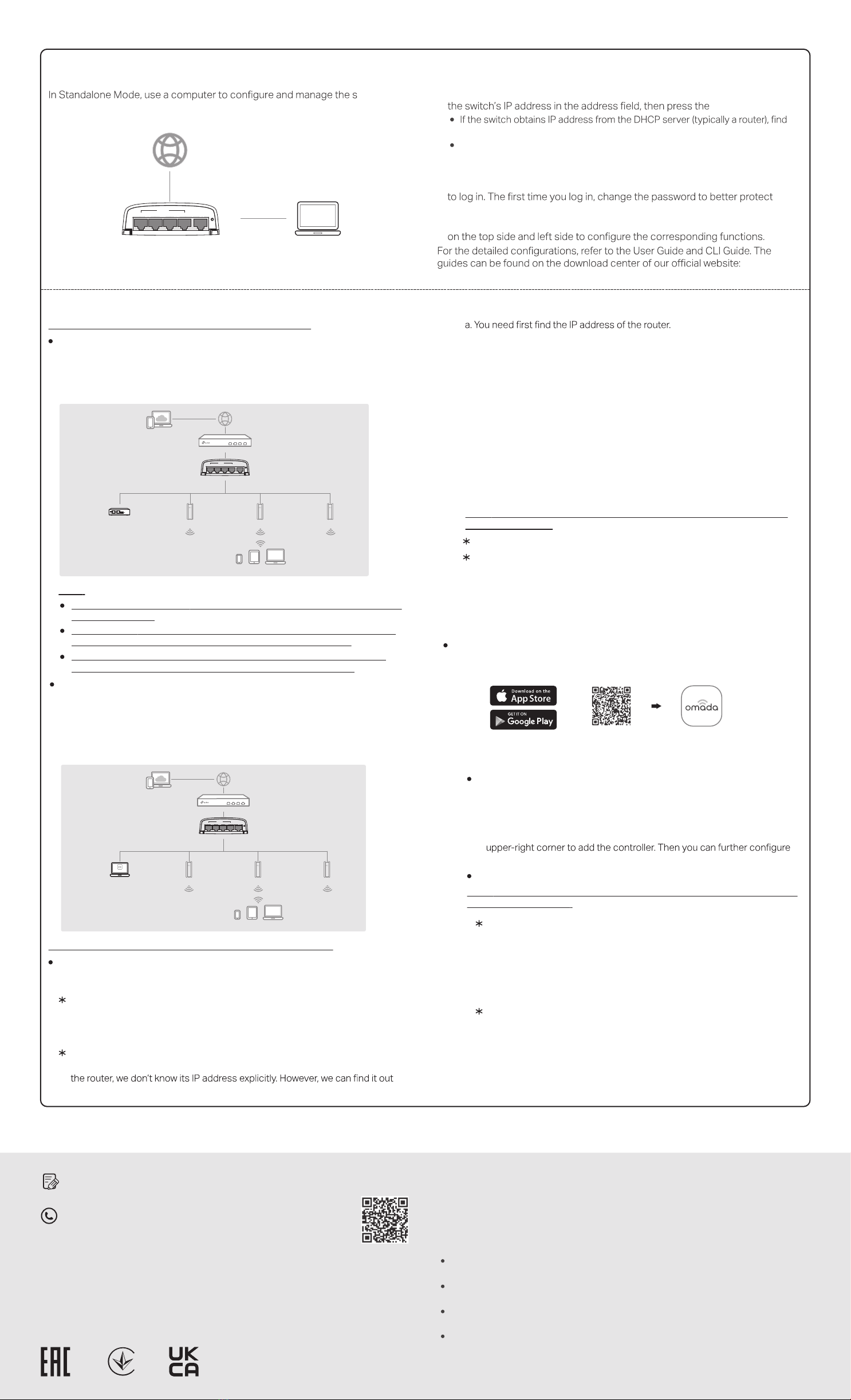
Method 2: Controller Mode
Switch
Router
Clients
EAP EAP EAP
Controller
Omada Software Controller
running on the Host PC
1 2
PoEOUT PoEIN
345
Reset
Choose from the following two types of Omada Controller:
On a PC with Windows OS or Linux OS, download the Omada Software Controller
from https://www.tp-link.com/support/download/omada-software-controller/.
Then run the le and follow the wizard to install and launch the Omada Software
Controller. To manage your devices, Omada Software Controller needs to keep
running on your computer.
Type 2: Omada Software Controller
Switch
Router
Clients
Omada Hardware Controller EAP EAP EAP
(OC200/OC300)
1 2
PoEOUT PoEIN
345
Reset
Note:
Before you start, be sure to power up and connect your devices according to
the topology gure.
A DHCP server (typically a router with DHCP function enabled) is required to
assign IP addresses to the EAPs and clients in your local network.
Omada Controller must have network access to your Omada devices (the
router, switch, and EAPs) in order to nd, adopt, and manage them.
Omada Hardware Controller (OC200/OC300) is a good alternative if you have no
spare PC to keep running Omada Software Controller in the network. It needs to
be purchased additionally. For more details, refer to the Installation Guide of
OC200/OC300.
Type 1: Omada Hardware Controller (OC200/OC300)
1. Open the Omada Controller’s web page.
Launch the Omada Software Controller on your PC. After the initiation process,
the controller automatically opens its web page. If not, click Launch a Browser
to Manage the Network.
For Omada Software Controller
As Omada Hardware Controller gets its IP address from the DHCP server of
on the router’s DHCP client list.
For Omada Hardware Controller
Choose from the following two types of Management Interface:
Type 1: Via Web Browser
1. Download the TP-Link Omada App on your mobile device. It can be downloaded
from App Store or Google Play:
3. After quick setup, login page appears. Enter the username and password you
have created and click Log in. Then you can further congure the controller.
2. On the Omada Controller’s page, follow the wizard to complete the quick setup.
Open the command line on
your PC and enter ipcong. In the result list, nd the Default Gateway, which
is also the IP address of the router.
c. Enter the IP address of your controller in address bar to open its web page.
b. Launch a web browser and enter the IP address of the router. Log into the
router’s web page, and both the username and password are admin by
default. Then go to Network > LAN > DHCP Client List to nd the IP address
of your controller according to its MAC address.
4. (For Remote Management) You can remotely access and manage your
controller via Omada Cloud Service.
Note: Before you start, make sure that both your controller and your PC can
access the internet.
For Omada Software Controller, refer to its User Guide
b. Launch a web browser and enter https://omada.tplinkcloud.com in the
address bar. Enter your TP-Link ID and password to log in. Click + Add
Controller and choose Hardware Controller to add your controller.
a. Make sure Cloud Access is enabled on your controller. By default, Cloud
Access is enabled. Make sure that the Cloud LED is ashing slowly.
For Omada Hardware Controller
Type 2: Via Omada App
2. Launch your Omada App and congure the controller at a local site or remote
site.
a. Connect your mobile device to the EAP by using the default SSID (format:
TP-Link_2.4GHz/5GHz_XXXXXX) printed on the label at the bottom of the
product.
b. Launch Omada App and go to Local Access, tap the +button on the
the controller.
Local Management
a. Make sure that Cloud Access is enabled on your controller and your
controller has been bound with your TP-Link ID.
b. Launch Omada App and log in with your TP-Link ID. Then go to Cloud
Access. A list of controllers that have been bound with your TP-Link ID will
appear. Then you can further congure the controller.
Note: Before you start, make sure that both your controller and mobile device
can access the internet.
For Omada Software Controller
a. Make sure that Cloud Access is enabled on your controller. By default,
Cloud Access is enabled. Make sure that the Cloud LED is ashing slowly.
b. Launch Omada App and log in with your TP-Link ID. Then go to Cloud
Access. Tap the +button on the upper-right to add your controller. Then
you can further congure the controller.
For Omada Hardware Controller
Remote Management
Download Omada App
or
Scan for Omada App
TP-Link hereby declares that the device is in compliance with the essential requirements
and other relevant provisions of directives 2014/30/EU, 2014/35/EU, 2011/65/EU and
(EU)2015/863.
The original EU declaration of conformity may be found at
https://www.tp-link.com/en/support/ce/
EU declaration of conformity
For technical support and other information, please visit
https://www.tp-link.com/support, or simply scan the QR code.
To ask questions, nd answers, and communicate with TP-Link users or
engineers, please visit https://community.tp-link.com to join TP-Link
Community.
Safety Information
Keep the device away from re or hot environments. DO NOT immerse in water or any
other liquid.
Do not attempt to disassemble, repair, or modify the device. If you need service, please
contact us.
This product can be powered only by power supplies that comply with Power Source
Class 2 (PS2) or Limited Power Source (LPS) of IEC 62368-1.
This device can only be installed by instructed persons and skilled persons.
TP-Link hereby declares that the device is in compliance with the essential requirements
and other relevant provisions of the Electromagnetic Compatibility Regulations 2016 and
Electrical Equipment (Safety) Regulations 2016.
The original UK declaration of conformity may be found at
https://www.tp-link.com/support/ukca/
UK declaration of conformity
1. To access the management page of the switch, open a browser and type
Enter key.
the switch’s IP address on the DHCP server.
If not, use the default IP address 192.168.0.1 to launch the switch’s
management page.
Note: Make sure the switch and computer are in the same subnet.
2. Enter admin for both the username and password in the lower case letters
your network and devices.
3. After a successful login, the main page will appear. You can click the menus
https://www.tp-link.com/support/download/.
Method 1: Standalone Mode
Switch PC
1 2
PoE OUT PoE IN
345
Reset
witch.