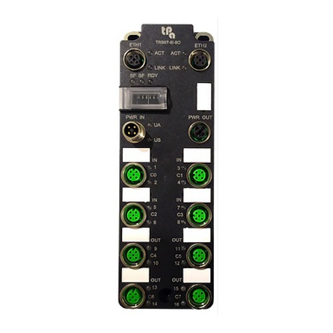
TPA TRS67-16I Operator's manual

1
TRS67-16I
Bus Coupler EtherCAT IP67
Documentation

2
Note
This instruction is used for TPA TRS67-16I Remote IO module.
This instruction is about the specifications, installation, main function and the configuration process of TRS67-16I
IP67 Remote IO module.
Application
This instruction application to the following:
Electrical engineer
Field installation workers.
Disclaimer
This manual is based on existing information, and its contents are subject to change without notice. Tpa has done
its best to ensure that its content is accurate and reliable when writing this manual but shall not be liable for the
loss and damage caused by omission, inaccuracy or typographical errors in this manual.
Product information
The TRS67-16I series remote IO module is a 16-channel industrial digital input and output module independently
developed by Tpa that complies with the EtherCAT V 5.1 communication protocol. This series of products uses
M12 T Code coded connectors for power supply.
All channel ports of the EC16 series support fault diagnosis alarms and short-circuit self-recovery functions,
which can help engineers quickly locate and find on-site faults and reduce maintenance costs.
Dimensions
ITEM INPUT OUTPUT
TRS67-16I
C0-C7

3
Description of each port
1.3.1 Signal and power
Contact definition
Contact No.
ETH (ETHERCAT)
PWR (POWER)
1
TX+
24 V (US+)
2
RX+
GND (UA-)
3
TX-
GND (US-)
4
RX-
24 V (UA+)
1.3.2 I/O signal
Contact definition
PIN Description
1 24V
2 PIN 2 signal
3
GND
4
PIN 4 signal
5
FE

4
Description of the light
Light indicator of EtherCAT and Power
Indicator light Color Definition State Description
LINK GN Connection
green
ETH 1/2 connected
extinguish
ETH 1/2 unconnected
ACT YE Acting
flash
ETH 1/2 data transmission
extinguish
ETH 1/2 without data transmission
RDY GN Ready
green Device turn on, will also remain after the normal
communication of the device is disconnected
flash Waiting for CPU synchronization
extinguish Device did not turn on
BF RD Break red Unconnected with EtherCAT control
extinguish
Connection with EtherCAT control
SF RD Inspection error red Inspection error exists
extinguish None
US GN/RD Sensor power
green US power supply normal
extinguish
US power supply out
red US power supply undervoltage (under 18 V)
UA GN/RD Device power
green UA power supply normal
extinguish UA power supply out
red UA power supply undervoltage (under 18 V)

5
Light indicator of I/O signal
Light Color Define State Description
2 GN/RD Signal performance of PIN 2
green Signal exists in Pin2
extinguish No signal exists in Pin2
red Pin2 output overload short circuit
2 @ 4 red at the same time Pin1 (power) overload short circuit
4 GN/RN Signal performance of PIN 2
green Signal exists in Pin4
extinguish No signal exists in Pin4
red Pin2 output overload short circuit
2.1 Connectors and Accessories
M12 connector – I/O TRS8.3.04
M12 connector – Power in TRS8.3.03
M12 connector – Power out TRS8.3.02
M12 connector – EtherCAT TRS8.3.01
M12 connector male to 2M8 female – I/O TRS8.3.05
M12 cover for female

6
2.2 Connect description
2.2.1 Device grounding
To avoid data damage or loss, please ensure that the device is well grounded.
2.2.2 Shielded Cable
To avoid data damage or loss, use the EtherCAT cable, ensure that the shielding layer of the cable is well grounded.
2.2.3 Power supply
TRS67-16I module power supply use M12 Tcode connection.
Module system and DI supported with US power supply, DO with UA power supply. Power range 18-30 VDC,
current 12 A. If the module uses series power supply, please pay attention to the voltage drop and the total
current of the power supply.
Typical connection diagram
2.2.4 IO connection
TRS67-16I series IO signal is PNP. Please pay attention to the wiring method when connecting the sensor and
actuator, below shown the typical connection diagram.
Typical Connection diagram input Typical Connection diagram output

7
2.3 Device fasten
Please use standard M4 screws to fix the module, the fixing surface should be kept flat, the module cannot bear
bending stress.
Chapter three: Configuration and operation instructions
3.1 ESI file
EC16 series use equipment description files (ESI) that comply with the EtherCAT V 2.3 standard
3.2 Main parameters
Housing material PC
Filler material Polyurethane
Metal material Copper nickel plated
Weight
300 g
Operating temperature
-25 – 60 °C
If the device is used at an ambient temperature higher than 50 °C, be careful
of high temperature burns when it contacts with the metal surface of the
device
Storage temperature From -30 to 70 °C
Operating humidity From 5% to 95%
Storage humidity
From 5% to 95%
Operating pressure
From 70 to 106 kPa
Protecting degree
IP67
3.3 EtherCAT
Port 2
Transmission Copper cable
Connect method M12 D code 4 pin
Transmission speed 100 Mbps
Device type EtherCAT Device
Consistency Class B
Refresh time 2 ms
EtherCAT protocol
COE FOE
3.4 US Device and sensor power supply
Connection method M12 T code 4 pin
Input voltage 18-30 VDC
Output current MAX 12 A
Reverse polarity protection YES
Current consumption 120 mA/no load
3.5 UA Actuator power supply
Connection method M12 T code 4 pin
Input voltage 18-30 VDC
Output current Max. 12 A
Reverse polarity protection Yes
Current consumption 5 mA/no load

8
3.6 IO connection
Connection method M12 A code 5 pin
Type PNP
Input type EN 61131-2 types 1 and 3
IO typical voltage 24VDC
Actuator current 500 mA/one signal
Sensor current 500 mA/one signal
Protection of overload and short circuit
870 mA/self-fixable
3.7 Electrical isolation
Testing parts
Testing voltage
US power Supply/ETH 1 500 VAC, 50 Hz, 1 Min
US power supply/ETH 2 500 VAC, 50 Hz, 1 Min
US power supply/FE 500 VAC, 50 Hz, 1 Min
ETH 1/FE 500 VAC, 50 Hz, 1 Min
ETH 2/FE 500 VAC, 50 Hz, 1 Min
ETH 1/ETH 2 500 VAC, 50 Hz, 1 Min
US/UA power supply 500 VAC, 50 Hz, 1 Min
UA power supply/ETH 1 500 VAC, 50 Hz, 1 Min
UA power supply/ETH 2 500 VAC, 50 Hz, 1 Min
UA power supply/FE 500 VAC, 50 Hz, 1 Min
3.8 Mechanical test
Vibration resistance according to EN60068-2-
6/IEC60068-2-6
5 g
Shock complies with EN 60068-2-27/IEC 60068-2-27 30 g, 11ms cycle, half-sine shock pulse
Continuous impact according to EN60068-2-
27/IEC60068-2- 27 10 g
3.9 EMC test
Noise immunity test complies with EN 61000-6-2 standard
ESD EN 61000-4-2/IEC 61000-4-2
Standard B, 6 kV contact discharge, 8 kV air discharge
Electromagnetic field EN 61000-4-3/IEC 61000-4-3
Standard A, field strength: 10 V/m
Electrical fast transient burst immunity EN 61000- 4-4
/IEC 61000-4-4
Standard B, 2 kV
Surge immunity (Surge) EN 61000-4-5/IEC 61000-4-5 Standard B, DC power cord: ±0.5 kV/±0.5 kV
(symmetry/asymmetry)
Conducted interference EN 61000-4-6/IEC
61000-4-6 Standard A; testing voltage 10 V
Noise emission test according to EN 61000-6-4
Radio interference EN 55022
Class A
Other TPA Control Unit manuals
Popular Control Unit manuals by other brands

WAREMA
WAREMA GA Kompakt Operating and installation instructions

Trenz Electronic
Trenz Electronic TEF1001 Schematics

H3C
H3C LSWM116FC user manual

tiki
tiki SHB10 Installation and user manual

Siemens
Siemens SINAMICS G120P Hardware installation manual

ShangHai Sunray Technology Co.,Ltd
ShangHai Sunray Technology Co.,Ltd SRWF-8009G user manual

DTM System
DTM System EASY B232 Installation and manual

Samson
Samson 2371 Series Mounting and operating instructions

EOS
EOS EmoTouch II + Installation and operation instruction

Bticino
Bticino AM4890 Installation

Rockwell Automation
Rockwell Automation Allen-Bradley PowerFlex 750 Series user manual

Control Techniques
Control Techniques DeviceNet user guide