manuals.online logo
Brands
  1. Home
  2. •
  3. Brands
  4. •
  5. LOVATO ELECTRIC
  6. •
  7. Control Unit
  8. •
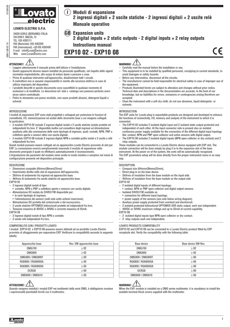
  9. LOVATO ELECTRIC EXP10 02 User manual

LOVATO ELECTRIC EXP10 02 User manual

I289 I GB 02 14 31100129
1
ATTENZIONE!!
–
Leggere attentamente il manuale prima dell’utilizzo e l’installazione.
–
Questi apparecchi devono essere installati da personale qualificato, nel rispetto delle vigenti
normative impiantistiche, allo scopo di evitare danni a persone o cose.
–
Prima di qualsiasi intervento sull’apparecchio, togliere tensione dagli ingressi di
alimentazione e dalle uscite relè dove presenti.
–
Il costruttore non si assume responsabilità in merito alla sicurezza elettrica in caso di
utilizzo improprio del dispositivo.
–
I prodotti descritti in questo documento sono suscettibili in qualsiasi momento di
evoluzioni o di modifiche. Le descrizioni ed i dati a catalogo non possono pertanto avere
alcun valore contrattuale.
–
Pulire lo strumento con panno morbido, non usare prodotti abrasivi, detergenti liquidi o
solventi.
INTRODUZIONE
I moduli di espansione EXP sono stati progettati e sviluppati per potenziare le funzioni di
connettività, I/O, memorizzazione ed analisi dello strumento base a cui vengono collegati.
In particolare il modulo EXP10 02 include 2 ingressi digitali isolati e 2 uscite statiche isolate
protette ed indipendenti fra loro. E’ disponibile inoltre sul connettore degli ingressi
un’alimentazione ausiliaria utile alla connessione delle varie tipologie di ingresso, quali:
contatti, NPN, PNP a collettore aperto e sensori attivi con uscita digitale. Questo modulo può
essere collegato ad un apparecchio Lovato Electric provvisto di slot per EXP. La connessione
evverrà semplicemente inserendo il modulo di espansione nello strumento principale il quale
ne effettuerà automaticamente il riconoscimento.
L’impostazione dei parametri del modulo viene svolta in modo intuitivo e semplice nel menù di
configurazione presente nel dispositivo principale.
DESCRIZIONE
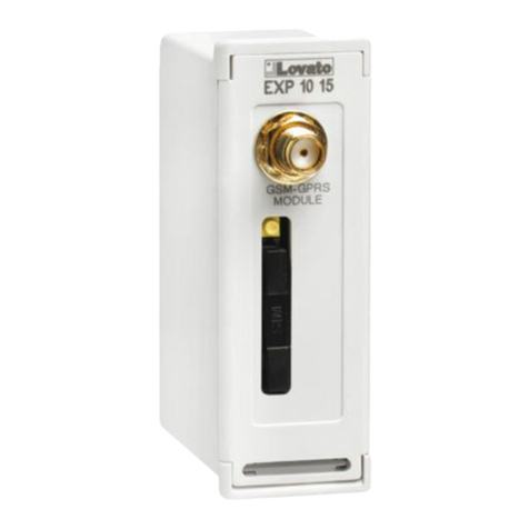
– Dimensioni compatte (64mmx38mmx22mm)
– Inserimento diretto nello slot di espansione dell’apparecchio.
– 2kVrms di isolamento fra ingressi ed apparecchio base.
– 4kVrms di isolamento fra uscite statiche ed apparecchio base.
– 2 ingressi digitali isolati di tipo:
• contatto, NPN o PNP a collettore aperto e sensore con uscita digitale.
– Alimentazione DC isolata da 24Vdc/1W disponibile per:
• le varie tipologie di ingresso;
• l’alimentazione dei sensori (vedi note sotto schemi inserzione).
– Alimentazione DC protetta dal cortocircuito e dal sovraccarico.
– 2 uscite statiche OPTOMOS protette ed indipendenti fra loro.
– Uscite statiche bidirezionali.
– Tensione massima di 40Vdc o 30Vac e corrente massima di 55mA.
COMPATIBILITÀ CON I PRODOTTI LOVATO
Il modulo EXP10 02 può essere abbinato ad un prodotto Lovato Electric provvisto di
alloggiamento per espansione EXP. Verificare la compatibilità secondo la seguente tabella:
Apparecchio base Rev. SW apparecchio base
DMG700 ≥02
DMG800 ≥02
DMG900 ≥00
ATTENZIONE!
Quando vengono installati i moduli EXP nei multimetri della serie DMG, è obbligatorio montare
i coprimorsetti piombabili forniti con il multimetro.
LOVATO ELECTRIC S.P.A.
24020 GORLE (BERGAMO) ITALIA
VIA DON E. MAZZA, 12
TEL. 035 4282111
FAX (Nazionale): 035 4282200
FAX (International): +39 035 4282400
E-mail info@LovatoElectric.com
Web www.LovatoElectric.com
EXP10 02
WARNING!
– Carefully read the manual before the installation or use.
– This equipment is to be installed by qualified personnel, complying to current standards, to
avoid damages or safety hazards.
– Remove the dangerous voltage from the product before any maintenance operation on it.
– The manufacturer cannot be held responsible for electrical safety in case of improper use of the
equipment.
– Technical data and descriptions in the documentation are accurate, to the best of our
knowledge, but no liabilities for errors, omissions or contingencies arising therefrom are
accepted. Products illustrated herein are subject to alteration and changes without prior
notice.
– Clean the instrument with a soft dry cloth, do not use abrasives, liquid detergents or
solvents.
INTRODUCTION
The EXP units for Lovato plug in expandable products are designed and developed to enhance
the functions of connectivity, I/O, memory and analysis of the instrument to which it is
connected.
The EXP10 02 includes 2 isolated digital input and 2 isolated static output protected and
independent of each other. At the input connector side is present also an isolated continuous
power supply available for the connection of the different digital input topology like: contact,
NPN and PNP open collector and active sensors with digital output. This module can be
connected to a Lovato Electric device equipped with EXP slot. The module connection will be
done simply by plug it in to the expansion slot of the base instrument. At the power on of the
system, the units will be automatically recognized.
The EXP parameters setup will be done directly from the proper instrument menu in an easy
way.
DESCRIPTION
– Compact size (64mmx38mmx22mm).
– Direct plug in on the base instrument.
– 2kVrms of insulation from the base module on the input side.
– 4kVrms of insulation from the base module on the output side
– 2 isolated digital input of different topology:
• contact, NPN or PNP open collector and digital output sensors.
– Isolated 24Vdc/1W available as:
• connection for different input topology;
• power supply of the sensors (see note below wiring diagram).
– Auxiliary power supply protected from overload and shortcircuit.
– 2 isolated protected OPTOMOS SSR each one independent.
– Bidirectional SSR.
– 40Vdc or 30Vac maximum voltage and up to 55mA of current capability.
LOVATO PRODUCTS COMPATIBILITY
EXP10 02 can be connected to a Lovato Electric product fitted by EXP receptacle slot. Verify
the compatibility with the following table:
Base device Base device SW Rev.
DMG700 >= 02
DMG800 >= 02
DMG900 >= 00
WARNING!
When the EXP. module is installed on a DMG series multimeter, it is mandatory to install the
sealable terminal block covers supplied with the multimeter.
I Modulo di espansione - 2 ingressi digitali - 2 uscite statiche
Manuale operativo
GB Expansion unit - 2 digital input - 2 static output
Instructions manual
I289 I GB 02 14 31100129
2
PROCEDURA DI CONNESSIONE DEL MODULO MODULE CONNECTION PROCEDURE
CLICK!
1234
1. Rimuovere le tensioni pericolose.
2. Rimuovere i coprimorsetti e la morsettiera estraibile.
3. Rimuovere il tappo di copertura dello slot nel quale si intende inserire il modulo.
4. Inserire l’EXP10 02 come indicato nella foto in alto.
5. Riposizionare la morsettiera estraibile e montare i coprimorsetti.
6. Alimentare lo strumento principale (verrà riconosciuto il nuovo modulo di espansione).
NOTA: per togliere il modulo, rimuovere ogni tensione pericolosa e ripetere in senso contrario le
operazioni dal punto 5 al punto 2. Premere nel punto indicato con per sganciare il modulo.
PROGRAMMAZIONE PARAMETRI
Per la programmazione dei parametri di configurazione del modulo si rimanda al manuale dello
strumento principale a cui lo si intende collegare.
1. Remove any dangerous voltage.
2. Remove the terminal covers and the terminal block.
3. Remove the expansion slot cover of the Lovato product at the position in which the EXP will be plug in.
4. Insert the EXP10 02 as illustrated in the above picture.
5. Replace the terminal block and the terminal cover.
6. Power up the system (the base product will automatically recognize the expansion unit).
NOTE: Remove any dangerous voltage and repeat the operations from step 5 to step 2 in the opposite
direction. Press in the point indicated by the in the picture in order to remove the module.
MODULE PARAMETERS SET-UP
For the EXP parameters configuration, see the manual of the main product to which it intends to connect.
I289 I GB 02 14 31100129
3
SCHEMI DI CONNESSIONE WIRING DIAGRAM
Disposizione morsetti
Terminal blocks position
+ IN1 IN2 -
Ingresso da sensori alimentati (vedi note sotto)
Supplied sensor inputs (See note below)
BU
BU
BN
BK
BK
BN
+ IN1 IN2 -
Disposizione morsetti
Terminal blocks position
13 14 23 24
Connessione uscite statiche
Solid state relay outputs connection
OUT 2
1413 2423
OUT 1
Ingressi da contatto non tensionato
Free voltage contact inputs
Connessione PNP
PNP connection
Connessione NPN
PNP connection
+ IN1 IN2 - + IN1 IN2 -
Corrente disponibile per alimentazione sensori:
Available current for sensors power supply:
Isens =42mA - n •7mA
42mA - Corrente massima dell’alimentazione DC
Max current of the DC power supply
n - Numero di ingressi utilizzati (compresi i sensori)
Number of inputs used (sensor included)
7mA - Corrente assorbita dall’ingresso
Input current consumption
Esempio:
Example:
1 ingresso utilizzato con 1 SSR ed 1 ingresso sensore
1 input used with 1 SSR and 1 sensor input
Isens=42mA - 2•7mA=28mA
Tolerance Envelope Graph
+10%
+5%
Nominal
Voltage
Output Voltage
Output Current (%)
10% 50% 100%
+2.5%
-2.5%
-7.5%
DIMENSIONI MECCANICHE [mm] MECHANICAL DIMENSIONS [mm]
64.5
38.2
22.0
46.8
I289 I GB 02 14 31100129
4
CARATTERISTICHE TECNICHE
Alimentazione
Tensione alimentazione 5V (fornita dallo strumento principale)
Corrente assorbita 250mA
Potenza assorbita/dissipata 1,25W
Ingressi digitali
Numero di ingressi 2
Tipo di ingresso Indifferentemente positivo o negativo
Corrente d’ingresso 7mA
Segnale d’ingresso alto ≥17,6V se IN di tipo PNP
≤6,4V se IN di tipo NPN
Segnale d’ingresso basso Al terminale IN deve essere connesso
un segnale open collector
Ritardo del segnale d’ingresso ≥50ms
Frequenza massima (INGRESSO 2000Hz
IMPOSTATO COME CONTATORE)
Frequenza massima (INGRESSO 50Hz
IMPOSTATO COME LETTURA STATO)
Tensione presente sui morsetti + e - 24V= isolata (valore nominale)
Vedi il grafico di “tolerance envelope graph”
per la tolleranza.
Massimo carico sui morsetti + e - 42 mA (protetti contro sovraccarico e corto
circuito)
Al superamento della corrente massima
interviene la protezione e la tensione verrà tolta.
Uscite statiche
Tipo di uscite Relè allo stato solido
(Opto-MOSFET)
Portata uscite statiche (a 60°C) 40V= / 30 V~ 55mA max
Connessioni
Tipo di terminali Morsetti estraibili
Numero di morsetti 4
Sezione conduttori (min e max) 0,2...1,5 mmq (28÷14 AWG)
Coppia di serraggio 0,18 Nm (1,7 LBin)
Connessione uscite statiche
Tipo di terminali Morsetti estraibili
Numero di morsetti 4
Sezione conduttori (min e max) 0,2...1,5 mmq (28÷14 AWG)
Coppia di serraggio 0,18 Nm (1,7 LBin)
Condizioni ambientali di funzionamento
Temperatura d’impiego -20 - +60°C
Temperatura di stoccaggio -30 - +80°C
Umidità relativa <90% (IEC/EN 60068-2-70)
Grado di inquinamento ambiente massimo 2
Categoria dì sovratensione 3
Altitudine ≤2000m
Sequenza climatica Z/ABDM (IEC/EN 60068-2-61)
Resistenza agli urti 15g (IEC/EN 60068-2-27)
Resistenza alle vibrazioni 0.7g (IEC/EN 60068-2-6)
Tensione di isolamento
Tensione nom. di tenuta a impulso Uimp 4kV
Tensione di tenuta a frequenza d’esercizio 2kV
Connessione al prodotto base
Tipo di connettore Connettore ad innesto
Contenitore
Dimensioni 64,5mmx38,2mmx22mm
Montaggio Ad inserimento nello slot di espansione
plug in EXP
Materiale Poliammide RAL 7035
Grado di protezione IP20
Peso 50g
Omologazioni e conformità
Omologazioni cULus
Conformità a norme IEC/EN 61010-1, IEC/EN 61000-6-2
IEC/ EN 61000-6-3, UL508 e CSA C22.2-N°14
UL « Marking » Use 60°C/75°C copper (CU) conductor only
AWG Range: 28 - 14 AWG stranded or solid
Field Wiring Terminals Tightening Torque:
1,7lb.in
I
TECHNICAL CHARACTERISTICS
Supply
Supply voltage 5V (supplied by main instrument)
Supply current 250mA
Power consumption/dissipation 1.25W
Digital inputs
Number of Inputs 2
Input type Positive or negative
Current input 7mA
“Input high” voltage ≥17,6V if IN is PNP type
≤6,4V if IN is NPN type
“Input low” voltage The input must be an open
collector signal
Input delay ≥50ms
Maximum frequency (INPUT 2000Hz
CONFIGURED AS COUNTER)
Maximum frequency (INPUT 50Hz
CONFIGURED AS STATUS)
Auxiliary voltage presents on 24V= isolated (nominal value)
the + and - pins See the “tolerance envelope graph” below for
the voltage tolerance.
Maximum load of the +and - pins 42mA (overload and short circuit protected)
If the load exceed the maximum current
capability the voltage will be removed
(protection activated)
SSR outputs
Output type Solid state relays
(Opto-MOSFET)
Solid state output rating (at 60°C) 40V= / 30 V~ 55mA max
Connections
Type of terminal Plug in/Removable termina type
Number of terminals 4
Cable cross section (min… max) 0.2…1.5 mm² (24…12 AWG)
Tightening torque 0.18 Nm (1.7 lbin)
Static output connection
Connection Plug in/Removable termina type
Number of terminals 4
Cable cross section (min… max) 0.2…1.5 mm² (24…12 AWG)
Tightening torque 0.18 Nm (1.7 lbin)
Ambient operating conditions
Operating temperature -20 - +60°C
Storage temperature -30 - +80°C
Relative humidity <90% (IEC/EN 60068-2-70)
Maximum pollution degree 2
Overvoltage category 3
Altitude ≤2000m
Climatic sequence Z/ABDM (IEC/EN 60068-2-61)
Shock resistance 15g (IEC/EN 60068-2-27)
Vibration resistance 0.7g (IEC/EN 60068-2-6)
Insulation voltage
Rated impulse withstand voltage Uimp 4kV
Power frequency withstand voltage 2kV
Base product connection
Terminal type Plug-in connector
Housing
Dimensions 64.5mmx38.2mmx22mm
Mounting For inclusion in the EXP plug in
expansion slot
Material Polyamide RAL7035
Degree of protection IP20
Weight 50g
Certifications and compliance
Certifications cULus
Compliant with standards IEC/EN 61010-1, IEC/EN 61000-6-2
IEC/ EN 61000-6-3, UL508 and CSA C22.2-N°14
UL Marking Use 60°C/75°C copper (CU) conductor only
AWG Range: 28 - 14 AWG stranded or solid
Field Wiring Terminals Tightening Torque:
1.7lb.in
GB

Other LOVATO ELECTRIC Control Unit manuals

LOVATO ELECTRIC EXP10 16 User manual

LOVATO ELECTRIC

LOVATO ELECTRIC EXP10 16 User manual

LOVATO ELECTRIC EXP10 10 User manual

LOVATO ELECTRIC

LOVATO ELECTRIC EXP10 10 User manual

LOVATO ELECTRIC EXS4000 User manual

LOVATO ELECTRIC

LOVATO ELECTRIC EXS4000 User manual

LOVATO ELECTRIC EXP10 15 User manual

LOVATO ELECTRIC

LOVATO ELECTRIC EXP10 15 User manual

LOVATO ELECTRIC DCTL Series User manual

LOVATO ELECTRIC

LOVATO ELECTRIC DCTL Series User manual

LOVATO ELECTRIC EXM10 11 User manual

LOVATO ELECTRIC

LOVATO ELECTRIC EXM10 11 User manual

LOVATO ELECTRIC ATL DPS1 User manual

LOVATO ELECTRIC

LOVATO ELECTRIC ATL DPS1 User manual

LOVATO ELECTRIC RGK700 User manual

LOVATO ELECTRIC

LOVATO ELECTRIC RGK700 User manual

LOVATO ELECTRIC DCTL Series User manual

LOVATO ELECTRIC

LOVATO ELECTRIC DCTL Series User manual

LOVATO ELECTRIC EXP10 10 User manual

LOVATO ELECTRIC

LOVATO ELECTRIC EXP10 10 User manual

LOVATO ELECTRIC EXP10 30 User manual

LOVATO ELECTRIC

LOVATO ELECTRIC EXP10 30 User manual

LOVATO ELECTRIC EXS4000 User manual

LOVATO ELECTRIC

LOVATO ELECTRIC EXS4000 User manual

LOVATO ELECTRIC EXP10 14 User manual

LOVATO ELECTRIC

LOVATO ELECTRIC EXP10 14 User manual

LOVATO ELECTRIC EXP10 02 User manual

LOVATO ELECTRIC

LOVATO ELECTRIC EXP10 02 User manual

LOVATO ELECTRIC EXP10 02 User manual

LOVATO ELECTRIC

LOVATO ELECTRIC EXP10 02 User manual

LOVATO ELECTRIC FF128EP Series User manual

LOVATO ELECTRIC

LOVATO ELECTRIC FF128EP Series User manual

LOVATO ELECTRIC EXM10 12 User manual

LOVATO ELECTRIC

LOVATO ELECTRIC EXM10 12 User manual

LOVATO ELECTRIC EXS0000 User manual

LOVATO ELECTRIC

LOVATO ELECTRIC EXS0000 User manual

LOVATO ELECTRIC EXM 10 12 User manual

LOVATO ELECTRIC

LOVATO ELECTRIC EXM 10 12 User manual

LOVATO ELECTRIC EXM10 13 User manual

LOVATO ELECTRIC

LOVATO ELECTRIC EXM10 13 User manual

LOVATO ELECTRIC EXP10 30 User manual

LOVATO ELECTRIC

LOVATO ELECTRIC EXP10 30 User manual

LOVATO ELECTRIC EXP10 15 User manual

LOVATO ELECTRIC

LOVATO ELECTRIC EXP10 15 User manual

LOVATO ELECTRIC RGK800 User manual

LOVATO ELECTRIC

LOVATO ELECTRIC RGK800 User manual

LOVATO ELECTRIC RGK800 User manual

LOVATO ELECTRIC

LOVATO ELECTRIC RGK800 User manual

Popular Control Unit manuals by other brands

Pickering PXI BRIC 40-569 user manual

Pickering

Pickering PXI BRIC 40-569 user manual

IDEC HR6S-S Original instructions

IDEC

IDEC HR6S-S Original instructions

FIRETRACE 800095-A installation manual

FIRETRACE

FIRETRACE 800095-A installation manual

Emerson Fisher Type H800 instruction manual

Emerson

Emerson Fisher Type H800 instruction manual

Bolymin BEGV643A Series user manual

Bolymin

Bolymin BEGV643A Series user manual

Eliwell Coldface EWHT800LX Series manual

Eliwell

Eliwell Coldface EWHT800LX Series manual
Vega plicscom operating instructions

Vega

Vega plicscom operating instructions

Kohler TOUCHLESS K-13686 installation guide

Kohler

Kohler TOUCHLESS K-13686 installation guide

Rothenberger ROSCAN 150 Instructions for use

Rothenberger

Rothenberger ROSCAN 150 Instructions for use

Avaya M460ML-SPV installation guide

Avaya

Avaya M460ML-SPV installation guide

Fadisel cebek TF-3 quick start guide

Fadisel

Fadisel cebek TF-3 quick start guide

Allen-Bradley 1785-KE user manual

Allen-Bradley

Allen-Bradley 1785-KE user manual

DMEGC DM M 156-60 Series installation manual
DMEGC

DMEGC DM M 156-60 Series installation manual

ARMTEL ACM-IP2.1 user manual

ARMTEL

ARMTEL ACM-IP2.1 user manual

Velleman VMA318 user manual

Velleman

Velleman VMA318 user manual

Rapid Controls SAB-QS quick start

Rapid Controls

Rapid Controls SAB-QS quick start

Bardiani BBYQ Instruction, use and maintenance manual

Bardiani

Bardiani BBYQ Instruction, use and maintenance manual

Dungs GSV Series instructions

Dungs

Dungs GSV Series instructions

manuals.online logo
manuals.online logoBrands
  • About & Mission
  • Contact us
  • Privacy Policy
  • Terms and Conditions

Copyright 2025 Manuals.Online. All Rights Reserved.